

Page 1

r @ e # @ ''
2 9 9 8 D IS K D R IV E
T E C H N I C A L M A N U A L
C R O M E M C O . Inc .
2 8 O B e rn a rd o A v e nu e
M o un ta in V ie w , C A 9 4 0 4 3
P art N 0 .0 2 3 - 6 0 0 0 A p ril 1 9 8 1
C opyright (C) 19 8 0
B y C R O M E M C O , lnc .
A L L R IG H T S R E S E R V E D
Page 2
FUNCT ION OF H ICROPROCESSOR IN 299 6
Tbe m icroprocessor implementation on 299 B performs three malor functlons .
T he se a re se rvo con t ro l, read y s ta tus , and e ra se de lay t im ing . The pro ce sso r
co nt inuo us ly execu tes a sequence o f ro ut ine s wh lch t rack the statu s o f ready
and se rve fun c t ion s , an d tes t the co nd lt ion o f th e se lec t l ine s to d e te rm ine
w he the r to o utp ut suc h sta tus . Beca use se e k ing a nd w r lt ing a re mu tua lly ex -
c lu s îve fu nc t io n s . T he p roc es so r a lso ha s t im e to ca lcu la te e ra se t lm ing .
Se rvo Co n t ro l
R he n the po s it po ne r 7s bo ld ing o n t rac k , the p ro ce sso r is ou t o f the se rvo
loo p , a llow ing 1' F INE PO S IT IO N SENS E '' to ke e p t he po s ît io ne r Cn p lace . khe n
seek ing to a track , the p roce sso r outputs a ve loc ity va lue wh ic h d ire ct ly co n-
tro ls the po s it io ne r w h ile co un t lng ste p an d de ten t p ulse s . Th e p roce sso r also
de te rm lne s w he n to sw itch itse lf into and o ut o f the feed bac k loo p . To e nsu re
m in im um re spo nse time to ch a nge s in se rvo sta tu s , b0 th ET EP p u lse s and DET ENT
pu lse s a re t ied to the INTE RRUP T inpu t o f the proce sso r . Th us , wh ene ve r a
st im u lus îs re ce ive d , the p roc e sso r sto ps w ha te ve r it w a s do ing a t the t /me ,
ide nt if ies the sou rce o f the in te r rup t , and tre a ts it app ro p ria te ly . T he ve l-
oc ity fo r the se rvo is de pend en t upon th e d istan ce re m a in in: to t rave l , a nd a
va lue for each ha lf-track of rem a ln ing d istance up to 63 tracks is sto red
in a look-up tab le ln memory . For greater than 6) tracks the max imum ve loc ity
b ou tp ut . T he D IRE CT IO N l ine ls sam p led a t the sta rt of a se ek and sto red fo r
the d u ra t io n o f tha t see û . lt is o u tp u t to th e D to A c on ve rte r a s the m o s t s ig -
nificant bit or slgn bit. By inlecting a current equal to one half the full
scale output through R1O3 and R10ù înto the D-A co nve rte r outpu t , a un i-po la r
dev lce ca n be use d to pro v ide s ig n ed d ua l po lar ity o u tpu t .
Upo n reach lng a d lf fe ren ce o f ze ro be twee n ste ps and d e ts n ts , the se rvo îs
sw itched to the HO LD mode fo r f lna l se tt ling to t rack . The proce sso r clea ns up
reglsters and track counters, and samples TKCENT (track center) and TKJ; (track
zero), storing them for future outgut conditîonal on selected status.
T he p roce s so r a lso co n t ro ls the RE ST OR E fu nc t îon . REST OR E ma y be în it ia te d
by the ho s t v la the RE STO RE inp u t , o r w il l o cc u r if a n il leg a l se e k is com -
manded ltoo many step pulses) or Cf a detent is received while hold in: on track.
Page 3

The bu ilt- in exe rciser on the 29j 8 automatica lly w r ite-protects tbe drive
by ho ld ing SEEK COMPL ETE fa lse in the e xe rc zse r mo de .
Re ad y Sta tus
The proce sso r wa tc he s the fou r index lln e s fo r change s . A com ple te low -h igh -
1ow se que nce be lng de te cted o n e ithe r d lske tte sta rt s a t im e r fo r tha t d iske tte .
The coun t ls te sted f requen tly , a nd shou ld 2Q0m S e la pse be fo re anothe r index
pulse is sensed , the d iskette îs logged no t ready . In 299 B it is stored
Inte rna l ly and o u tput on ly fo r the se lecte d d iske tte . Tw o -s zded inde x is sam p led
whe n '' EITHER INDEX 11 is h lg h and sto red fo r ou tpu t to the ho st .
E ra se De la y T im ing
Th e use o f tunne l-e ra se head s ma nda tes a de lay c ha nge s in % R IT E G AT E and
ERASE GATE. The processor allows a refinement of this delay by adlustlng it
acco rd ing to the t rac k loca t ion . T he INT ERRU PT c lrcu it is co nf lgu red such tha t
either edge of WRITE GATE (turn-on or turn-off) causes an lnterrupt. When thls
inte rrupt is lden t if îed , R R IT E GAT E ST AT U S is te ste d a nd the a pp ro pr îa te d e lay
Is ge ne ra ted ; longe r de lay s fo r tu rn -o ff and va ry lng length s depe nde nt upon the
track loca tlon . De nse r fo rmats tha n w e re ava ilab le w ith fixes de lay s can be
o bta lne d .
Page 4
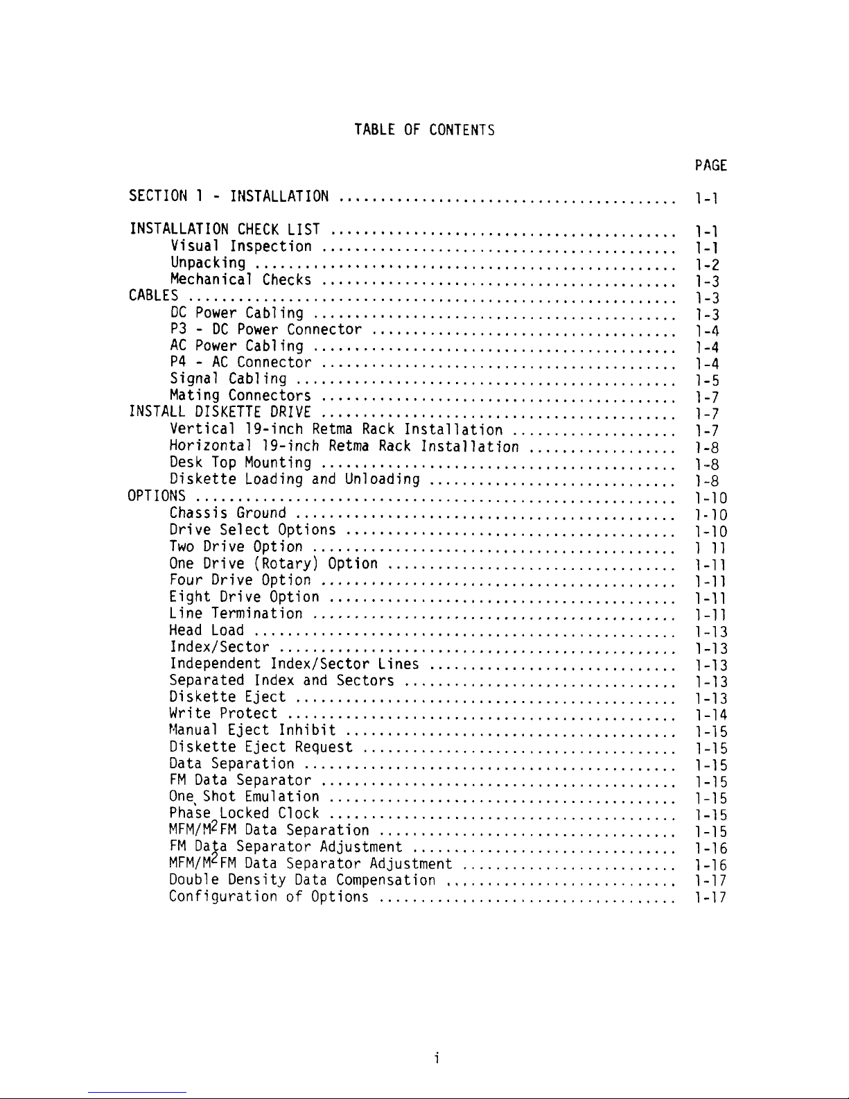
TABLE O F CONTENTS
PAGE
SECT IOK 1 - INSTALLAT ION ...............................
. . . . . . . . . . 1-1
INSTALLAT ION CHECK LIST .................,......
. . . . . . . . . . . . . . . . . .
1-1
14 i s u a 1 I n s ;) (, c 1; 1- () n . . . . . . . . . . . . . . . . . . . . . . . . .
. . . . . . . . . . . . . . . . . .
1 - 1
hltl C h a n 1* (: a 1 C h (, c k S . . . . . . . . . . . . . . . . . . . . . . . . . . . . . . . . .
. . . . . . . . . .
1 - 3
1::1 (512 1::1 1::j lkhdr 152! 14*% 1::2 iilk I1:i *1 -1' 4'11 !g4l . . . . . . . . . . . . . . . . . . . . . . . . . .
. . . . . . . . . . . . . . . . . .
-1 --- 111:
P3 - DC power Connecto r ...............................
. . . . . .
1-4
/1 C P 0 k:e r C a b ) 1 n g . . . . . . . . . . . . . . . . . . . . . . . . . . . . . . . . . . . . . . . . . . .
.
) - 4
? 4 - /$ C C 0 n n e C t 0 r . . . . . . . . . . . . . . . . . . , . . . . . . . . . . . . . . .
. . . . . . . . .
1 - 4
S 1- g n a 1 C a b l 1- n g . . . . . . . . . . . . . . . . . . . . . . . . . . . . . . . - . . . . . . . .
. . . . . .
1 - S
h1 ; t 1- n g C 0 n n e C t O r S . . . . . . . . . . * . . . . . . . . . . . . . . , . . . . . . . .
. . . . . . . . .
1 - 7
INSTALL D ISKETTE DR IVE .................................
. . . . . . . . . .
)-7
Vert ical lg-inc h Retma Rac k Installat ion ..............
. . . . . .
1-7
Ho rizontal 19- 1'nch Retma Rack lnstallat l'on ............
. . . . . .
1-8
E) (! S k 17 () p h1 () u n t i n g . . . . . . . . . . . . . . . . . . . . . . . . . . . . . . . . . . . . .
. . . . . .
1 - E$
Diskette Load ing and onload p'ng ........................
. . . . , .
1-8
ChaSSI'S Ground ...................................,.........
. 1-10
Drive Select Options .......................................
.
1-10
17 kk () () r 1- v t! () p t )- () n - . . - . . - . . . . . . . . . . . . . . . . . . - . . . . . . . . . . . . . . . . . . ) 1 )
0ne Drive (Rotary) Option ................................... 1-11
F () u r () r 1- v i? () p t 1- () n . - . . . . . . . . . . . . . . . . . . - . . - . . . . . . . . . -
. . . . . . . . .
1 - 1 1
E 1- g h t D 4% 7- v (, () p t 1 o n . . . , . . . . . . . . . . . . . . . . . . . . . . . . . . . . . . . .
. . . . . . 1 - 1 1
L 7- n (, lr (, ywrr 1- n a t 1- () n . . . . . . - - . . . . . . . . . . . . . . . . . . . . . . . . . . . . . .
. . . . . .
) - 1 1
lndex/sector ................................................ 1-13
Independent Index/sector Lines .............................. 1-13
Sepa ra ted Inde x and Sec to rs . ,. .... .,., ... ...
. . . . . . . . . . . . . . . .
1-13
(2h 1* 1; $( (, 1: 17 (? !! J- (! (2 1: . . . . . . . . . . . , . . . . . . . . . . . . . . . . . .
. . . . . . . . . . . . . . . . 1 -- 1 :$
l!1 k, 1* 1) (! F' ke (:p 1: (, (: 1: . . . . . . . . . . . . . . . . . . . . . . . . . . . . .
. . . . . . . . . . . . . . . . . .
1 -- 1 dl
l'la n u al E je c t I n hi bi t . . . . . . . . . . . . . . . . . . . . . . . . . . . . . . . . . . . . . . . . 1 -1 5
Di s k e t t e Eje c t Re q u e s t . . . . . . . . . . . . . . . . . . . . . . . . . . . . . . . . , . . . . . 1 -1 5
Da t; Se P; r; t1'0 9 ... .. .... .... .. .. .... .. .... .. .... ..
. . . . . . . . . . 1 -1 6
FM Da ta Se pa ra t0 r ....... ...... ........ ... .. ........ ...... ..
.
1 - 1 S
0n e
.
ShO t Em ul a t ion ..... ...... .... ....... ... .... ...... .... ... 1 -1 5
P ha Se L0C ked C1 Oc k ........ ... ....... ...... -.......
. . . . . . . . . .
1 -1 5@
FH Data Se paration ..........................
. . . . . . . . , .
1-15MFH/H
FR Data Separator Adjustment ..........................,..... 1-162
FM Data Separator Adjustment ....................,..... 1-16HFM/M
Do ub le De nsity Data Com pensat l'o n .....,.........,...,........ 1-17
Configu rat ion o f Opt ion s ... ................................. 1-17
1
Page 5
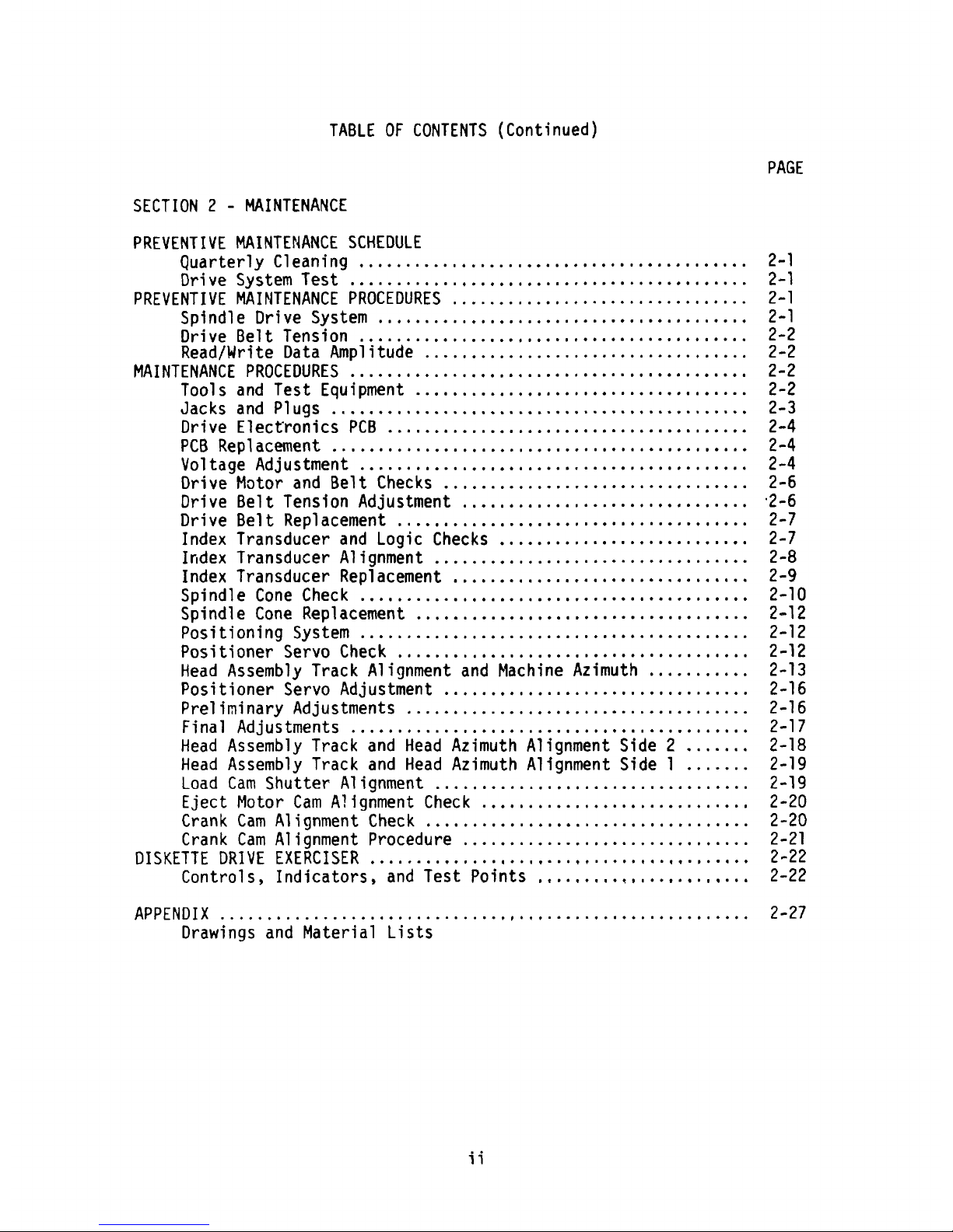
TABLE 0F CONTENTS (Continued)
PAGE
SECT ION 2 - HAINTENANCE
PREVENT IVE HA INTENANCE SCHEDULE
kuarterly Cleanl'ng ..,....................................... 2-1
DriMe Sy stem Test ......................,.................... 2-1
FREkENT IVE HA INTENANCE PROCEDURES .......,........................ 2-1
Splndle Dr ive Sy stem ........ ............,.............. ..... 2-1
Drive Belt Tens l'on .......................................... 2 -2
Read/krl'te Data Amplitude ....,.............................. 2-2
MA INTENANCE PROCEDURES ........................................... 2-2
Tools and Test Eqe l'pment ..............,..................... 2-2
JACQS and P1u9S ............................................. 2-3
Drive Elect'ronl'cs PCB ....................................... 2-4
PCB Replacement .......................................,..... 2-4
Voltage Adjustment .......................................... 2-4
Drive H otor and Belt Checks .................,............... 2-6
Drive Belt Tenslon Adjustment ............,.................. .2-6
Drive Belt Replacement ...................................... 2-7
lndex Transducer and Logic Checks ........................... 2-7
lrldex T ransducer A ll'gnment .................................. 2-8
Index Transducer Replacement ................................ 2-9
Spind le Cone Check .......................................... 2-10
Sp indle Cone Replacement .................................... 2-12
Positl'on ing Sy stem .......................................... 2-12
Positioner Servo Check .,.................................... 2 -12
Head Assembly Track A ll'gnment and Haciine Azimuth ........... 2-13
Positioner Servo Adjustment ........,...,..........,......... 2-16
prell'minary Adjustments ............................,..,..... 2-16
Final Adjustments ...............................,........... 2-17
Head Assem bly T rac k and Head Azimuth A ll'gnment Side 2 ....... 2-18
Head A ssembly Track and Head Azimuth Allgnment S ide 1 ....... 2-19
Load Cam Shutter Al ignment .................................. 2-19
Eject Motor Cam Allgnment Check ............................, 2-20
Crank Cam Alignment Check ................................... 2 -20
Crank Cam Alignment procedure ............................... 2-21
DISKETT E DRIVE EïERC ISER ..............
.
. . . . . . . . . . . . . . . . . . . . . , . . . . .
2-22
Contrcls , Indicators. and Test Po 'lnts ..............,....,... 2-22
D r aw 1- n g s a n d Ha t e r 1 a 1 L 1 s t s
1 1
Page 6
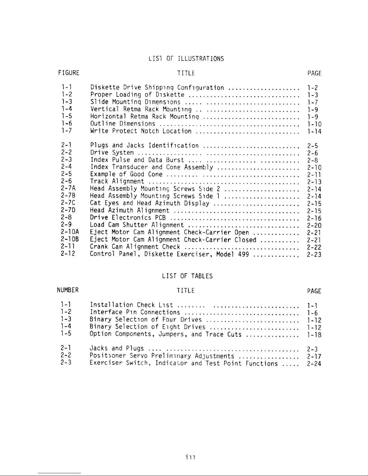
LISI 0 F ILLUST RAT IONS
FIGURE T ITLE PAG E
1- 1 Diskette Drive Shipplnq Con flguration .................... 1-2
l-2 Prope r Load ing of Dlskette ............................... 1-3
)-3 Slide Hountinq Dlmenspons ..... ,......................... 1-7
1-4 Ve rt ical Retma Rac k Hount lng .. .............. ............ 1-9
1-5 Hor izon ta l Retma Rack Mountinq ........................... 1-9
1 -6 Outl ine o l'men sïo ns - .. .. .... - .. ... .... ....... ... ... ... . . 1 -1 0
1 -7 H r l'te ? rotec t Notc h Loca t ion .- ..... . ... .. .... .... ., .... . 1 -1 4
2-1 P1 ug s and Jac ks Id en t î fl ca tion .....,... .. ..... ... .
. . . . . . . 2- 5
2-@ Dr1've S# StQm .................. ......... ............ .
. . . .
2-6
2-3 Index Pu lse and lata Bu rst .... ...... ... ... .. ... ... ... .. 2-8
2-4 Index Transduc er and Coce A ssem bly ................
. . . . . , .
2-10
2-5 Exam ple of Good Cone ......... ....... ........,........... 2-11
2-6 T rac k A lïjnm en t ..... .................................
. . . .
2- 13
2-7A Head Assem bly Hount qnç Sc rew s S lde 2 .... ............
. . . . .
2-14
2-78 Head Assem bly Mount lnj Screw s S lde 1 .............
. . . . . . . .
2-14
2-7C Cat Ey es and Head Azimuth D isplay ................
. . . . . . . .
2-15
2-7D Head Az l'm uth Alignment ..................................
.
2-1 5
2-8 Dr ive Elect ronl'cs PC8 ... ................................
. 2- 16
2-9 Load Cam Shutter A lignm ent ......... ..................
. . . . 2-20
2-10A Eject Motor Cam Alignment Check-carrier Open ............. 2-21
2-10B Eject Hotor Cam Alignment Check-carrier Clnsed ........... 2-21
2-11 Cran k Cam Alignment Check .........................
. . . . . . .
2-22
2-12 Control panel , D iskette Exerc iser , Model 499 ............
. 2 -23
LIST OF TA8LES
NUH8Eq T ITLE FAGE
7-1 Installat ion Check Llst ........ ..........
. . . . . . . . . . . . . .
1- 1
l-2 Inte rface P 1n Connect l'ons ......,.... .......
. . . . . . . . . . . . . .
1-6
1-3 Binary Se lectlon of Four Dr q'ves . ......... ..
. . . . . . . . . . . . . .
1-12
1-4 B inary Selection of Elçht Drives ........
. . . . . . . . . . . . . . . . .
1-12
l-5 Opt ion Com ponents , Jum pers , and I race Cuts
. . . . . . . . . . . . . . .
1-18
2 - 1 J a c k S a n d P 1 u g S . . . . . . . . . . . . - . . . . .
. . . . . . . - - . . . . . . . . . . . . . .
2 - 3
2-2 Po sit ione r Servo Prelim lnary Adlustments .
. . . , . . . . . . . . . . . .
2-17
2-3 Exe rc iser Sw itch , lnd icator and Test Po int Functions
. . . . .
2-24
7 1 1
Page 7
SECT ION )
IhSTALLAT ION
This sec tion contains procedu res to verîfy the operat ional integrity nf
the d iskette dr ive pr ior to on-line oper at ion .
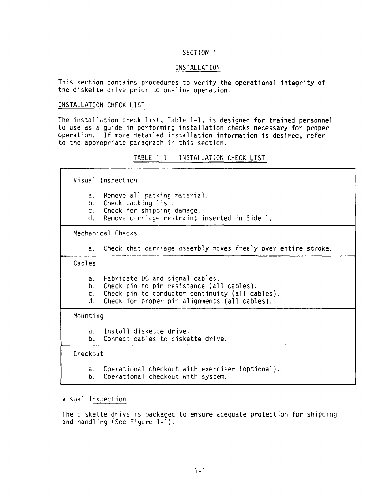
INSTALLAT IOh CHECK LIST
The insta llation chec k llst , Table 1-1 , is desijned for trained personne l
to use as a guide in performing installation checks necessart for proper
operat ion . If more de ta qled insta llation info rmat ion is de slred . refer
to the appropr iate paragraph in this sect ion .
TABLE 7-1 . INSTA LLAT ION CHE CK LIST
Visual In spectlon
a . Remo ve a1l pac king m aterial .
b . Chec k packing l ist .
c . Check for shlppins dam age .
d . Remove carriage restra int inserted in S ide 1 .
Hec han ical Chec ks
a . Chec k that carrïage dssem bly moves free ly over entlre stroke .
Cable s
a . Fabricate DC and sig nal cables .
b. Check pin to pin resistance (a11 cables).
c. Check pin to conductor continuity (a11 cables).
d. Check for prcper pin alignments (a11 cables).
Houn ting
a . Insta ll d iskette dr ive ,
b . Connect ca bles to d iskette dr ive .
Chec kout
a. Operational checkout with exerciser (optional).
b . Ope ra tiona l c hec kout w ith sy stem .
kisua l In spec tio n
The d iskette drive is packaged to ensure adequate pro tect îon for shipp ing
and handling (See Figure 1-1).
1-1
Page 8
ûUTSIOE CARDBOARD B0 X - -
%
%
x e N x
8 CORNER BLOCKS .-
l
%. I
l
*
-
*
I
I I l
1 --
INNER
CARDBOARD
-
B0XN
x N -DRIVE
CARRIAGE
RESTRA INT - e
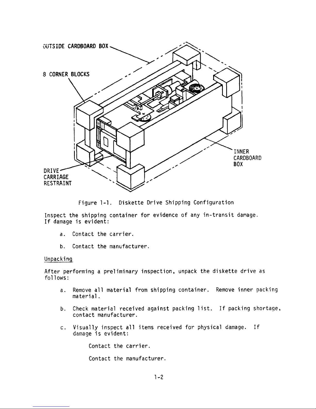
Figure 1-1 . Diskette Drive Shipping Configuration
Inspect the shiqping container for evidence of any in-transit damage.
If damage is evlten t :
a . Contact the carrier .
b . Contact the manu facturer .
Unpac king
After performing a prel îm inary inspect ion , unpack the dîskette drive a s
fo llow s :
a . Remcve a11 material from shipping container . Remove inner pac king
materlal .
b . Check m ateria l rece ived against packîng list . If pack ing shortage ,
con tac t ma nufactu rer .
c. kîsually insqect a11 items received for physical damage. lf
dam age qs ev lden t :
Contact the carrier .
Co ntact the manufacturer .
1-2
Page 9
- , '
A
x
LA BEL
d
!
N
<
HEAD SLOT
FORHARD
INDEï HO LE
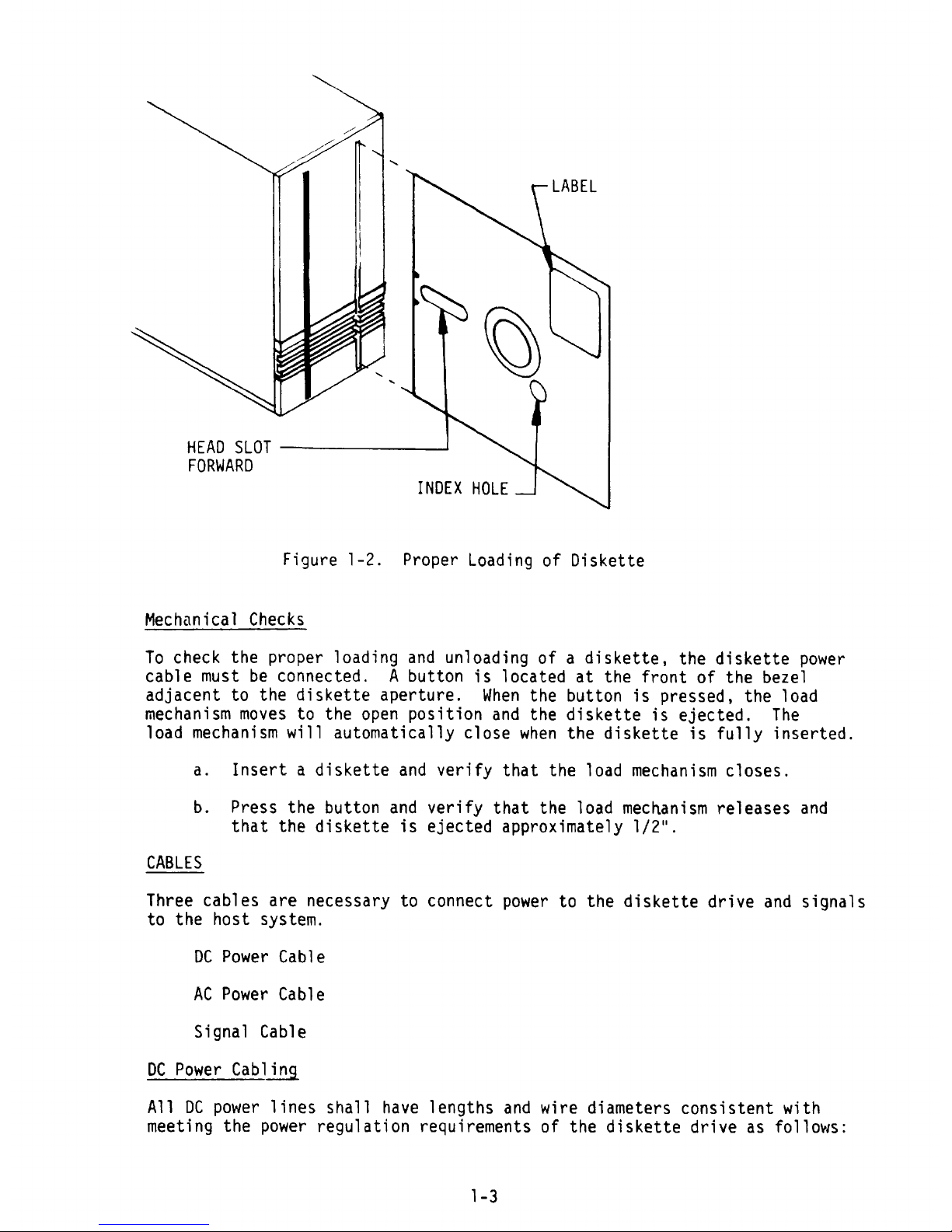
Fijure 1-2 . pro per Load ing of Diskette
Mechcnlcal Checks
To chec k the proper loading and unload ing of a diskette , the d iske tte pow er
cable must be connected . A button is located at the front of the beze l
adjacent to the diskette aperture. Hhen the button is pressed, the load
mechanism moves to the open position and the diskette is ejected. The
load mechanism w ill automatically close when the d iskette is fully inserted .
a . Inse rt a d iskette and ver ify that the load mechan ism clo se s.
b . press the button and Mer ify that the load mecNan ism releases and
that the diskette is ejected approximately 1/2'%
CABLES
Three cables are necessary to connect power to the d iskette d rive and signals
tn t he host sy stem .
DC Power Cable
AC Power Cable
Slgnal Cable
DC power Cabling
A11 DC pow er llne s shall have lengths and w ire d iameters consistent w ith
meeting the power regulation reguirements of the d iskette dr ive as fcllows :
1-3
Page 10
15V DE l 5% 2 .0 Am ps Max ., 50 mv p-p ripple
-
5k DC à 5% 0 .25 Amps M4x ., 50 mv p-p ripple
+24/ DC 1 5% 1 .0 Am ps Yax . seekinj w ith 2 .0 Amps
Max . peak
Seven lines are used to transmit DC power throu:h the power connector from
the power supply into a diskette drive. Qne lqne palr (high and ground)
is used for +5V DC , nne for +24V DC . and one for -5V DC . Iq addltïon , one
extra ground and one chassls :round are provsded .
Five-foot lengths of 418 AHG w ire are normally acceptable for use as DC
power lines between the drive and ty pical pcwer Gources.
Fabricate and check pcwer cable as listed f0r ?3 .
P3 - DC Pow
-
e r
-
connectp r
10 Pin Molex - 0 .156'' center
Pin Func tion Pin Functlon Mating
-
c
-
c nce cto r
1 Chassis Gnd 6 Ground Connector Molex 09-50-3101
2 +5V DC 7 Grcqnd Termlnal Molex 08 -50 -0106
3 Spare 8 Ground Polarizinq Key Holex
15-04-0219
4 Key 9 Ground
5 +24: DC 10 -5V DC
AC Power Cabling
AC power cabling should be fabricatrd from U.L. accepted ccrd capable Qf
carry ing 1 amp at the Moltage at w hlch the drive is to be operated .
P4 - AC Connector
3 P1 n Amp
Pin Funct fon Ha ti nq Connector
1 Motor Power ''A'' Houssng Amp 35076 6-1
2 Frame Groepd Termlnal Amp 350550 -3
3 Ho tor Power ''B ''
1-4
Page 11
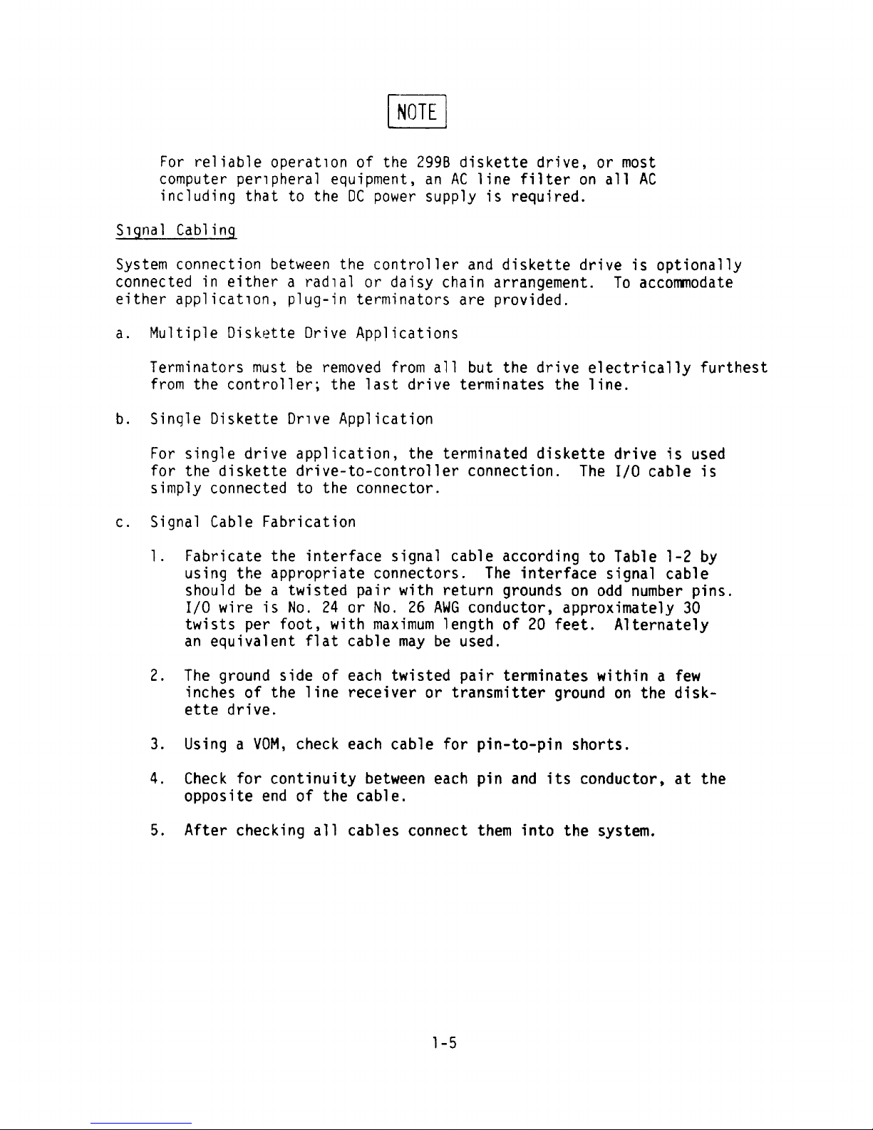
AOTE
For re liab le ope rat po n of the 2998 d is kette d rive , o r mo st
com puter pe rlpheral equ ipme nt . an AC l ine filter o n a11 AC
inc lud ing that to the OC power supply is requ ired .
S lgna l Cabl ing
Sy stem con nec tlo n be twee n the con tro lle r and d iske tte dr ive is opt iona lly
co nnected in e ither a rad lal or da isy cha in arrangement . T0 accommodate
eithe r app licatlon , plug-in te rm inato rs are prov ided .
a . Hu lt iple Dis kette Dr ive A pplicat ion s
Term ina to rs must be remo ved from a 11 but the dr ive electr ically furthest
from the controller ; the last d rive te rm înate s the l ine .
b . S inq le Diskette Drlve Appl ica tion
For single drive apqlication, the terminated diskette drive is used
for the diskette drlve-to-controller connection. The I/0 cable is
sim ply c onnected to t he co nne cto r .
c . S igna l C able Fabr icat io n
1. Fabr icate the interface s ignal cable accord ing to Table 1-2 by
using tbe appropriate connectors . T he interface s ignal cable
shou ld be a twisted pa ir w ith return grounds on odd num ber p ins .
I/0 wire is No . 24 or No. 26 AHG conductor. approximately 30
tw ists per foot . w ith max imum length of 20 fee t. Alternately
an eq uivalent flat cable may be used .
2 . T he g round side of each tw isted pa ïr term inate s w it hin a few
inc he s o f the line rece iver or tra nsm itter ground on the d isk-
ette dr îve .
3 . Usinj a V0H . check each cable for pin-to-pin shorts .
4 . Check for continu ity between each p in and its conductor , at the
oppos ite end o f the cab le .
5 . A fter che cking a11 cables co nnect them into the sy stem .
1-5
Page 12
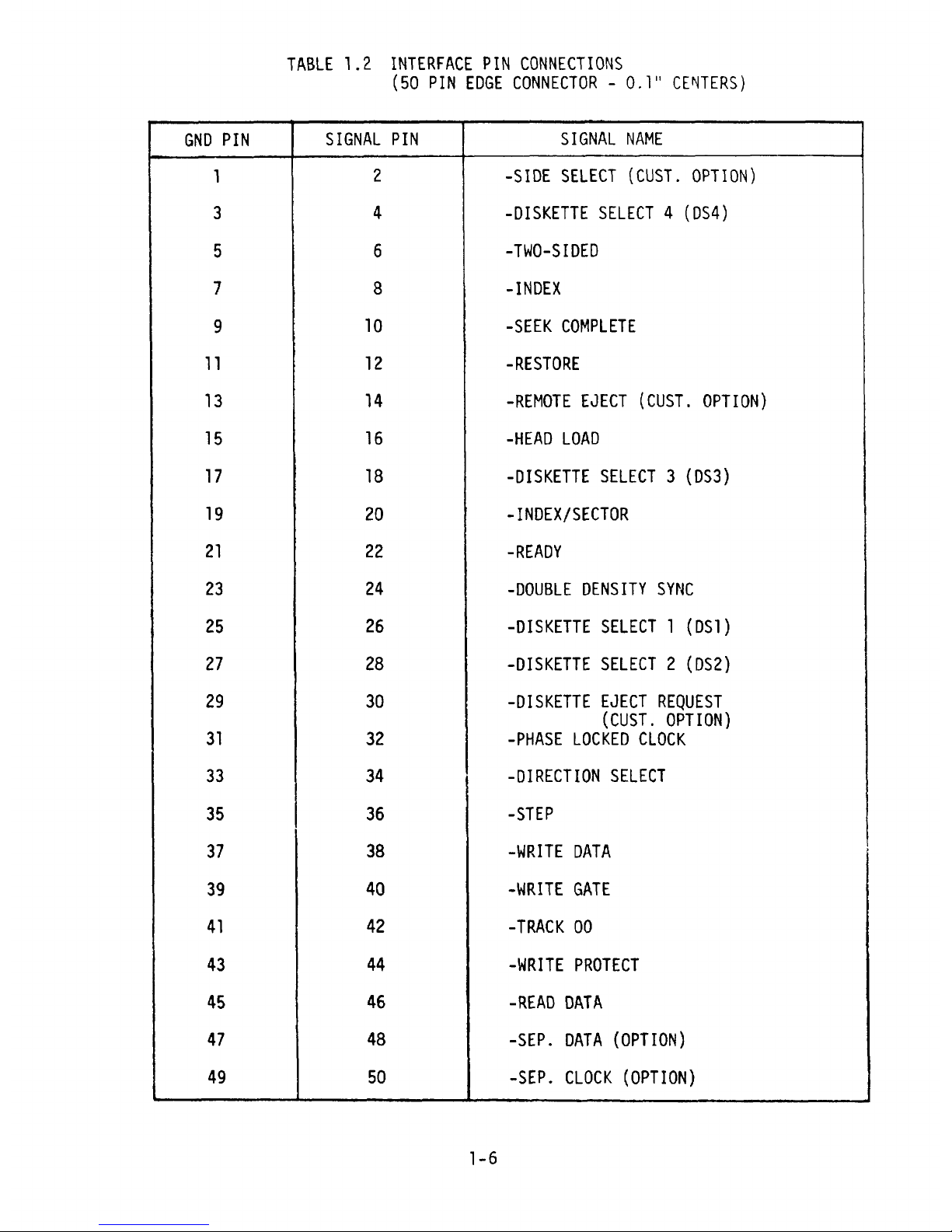
TABLE 1 .2 INTERFACE P IN CONNECT IONS
(50 P1N EDGE CONNECTOR - 0.1.' CENTERS)
GND P IN S IGNAL P IN SIGNAL NAH E
1 2 -SIDE SELECT (CUST. OPTION)
3 4 -DISKETTE SELECT 4 (9S4)
5 6 -THO-S IDED
7 8 -INDEX
9 10 -SEEK COHFLETE
11 12 -RESTORE
13 14 -REMOTE EJECT (CUST. OPTION)
15 16 -H EAD LOA D
17 18 -DISKETTE SELECT 3 (DS3)
19 20 -INDEX/SECTOR
21 22 -READ?
23 24 -DOUBLE DENS ITY S/NC
25 26 -DISKETTE SELECT 1 (DS1)
27 28 -DISKETTE SELECT 2 (DS2)
29 30 -DISKETTE EJECT RECUEST
(CUST. OPTION)
31 32 -PHASE LOC KED CLOCK
33 34 -DIRECT ION SELECT
35 36 -STE?
37 38 -HR ITE DATA
39 40 -HRITE GATE
41 42 -TRAC K 00
43 44 -HRITE PROT ECT
45 46 -READ DATA
47 48 -SEP. DATA (0pTI0N)
49 50 -SEP. CLOCK (0PTl0N)
1-6
Page 13
Ha ting Connecto rs
Vend or
kendor Part N
-
um ber com ment
Scotch Flex 3415-0000 Flat Cable
T & B Ansley 609-5005 Flat Cable
Viking 3VH25/1JN-5 Solder
Texas Instruments H312125 Solder
INSTALL D ISKETTE DRIVE
There are two methods of installing the diskette dr ive in a lg- inch Retma
rac k ;
Vert ical - 4 maximum
Horizon tal - 2 max imum
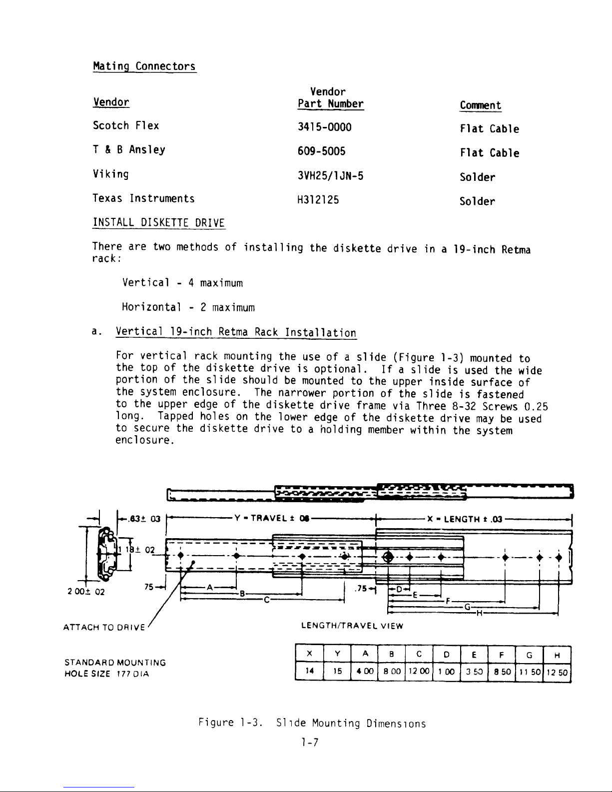
a . kertica l 19-înch Retma Rack Installation
For vertical rack mounting the use of a slide (Figure 1-3) mounted to
the top o f the d is kette drive is o pt iona l . If a sl ide is used t he w ide
portion of the slide should be m ounted to the uppe r inside surface of
the system enclosure . The narrcwe r port ion o f the slide is fastened
to the uppe r edge of the d iskette d rive frame v ia Three 8-32 Screw s 0
.
25
long . Tapped ho les on the lower ed ge of the diske tte d rive m ay be used
to secure the d iskette dr ive tn a hold ing m ember w ith in the system
enc lo sure .
V .0â. û3 Y - TRAVEL à œ X - LENGTH 1 .X
'
1 1 .t 02 ' ç . VK* ** R-Q Q < l '
-
# - - - -. + . -+ - - - + - +- - + --- - Y - # j
= - - . .
.
r .c - - . . l
i A j . 75M D q752 X.t Q2 B c
- F G
H
c L E N G T H JT q A V E L v lEwA U A C H T O D 8 IV
x Y A B C () E F G 8
STA N D A R (7 M O U N T IN G
14 1 s 4 a ) 8 00 1 2 (% 1 (m a 6,3 8 50 1 1 50 1 2 508 O LE S 4Z E ! 77 (3 IA
Fi gure 1 -3 . S 1 1 de Hount i ng Di men s 1 o ns
1 - 7
Page 14

Alternatively îf a slide is not used , ''skid rails'' w ithin the system
enclosure may be used . Up to four dr ives m ay be moqnted vertically
in a lg-inch Retma rack. (Flgure 1-û.) The vertical orientation of
the diskette drive must be as shnwn . Vertical mounting of the diskette
drive is preferred over horizontal mounting .
b . Hor izontal lg-inch zetm
-
a R
-
ac k Insta
.
llat îon
If two drïves are mounted horizontally, ''sk#d Rails'' must be used as
there is insufficïent space to use slldes . lf a sfngle d iskette drive
is mounted hor izonta lly s tw0 slides , cne on each side o f the d fske tte
frame , shou ld be used . The w ide porticn o f the sllde should be fastened
t: the system enclcsure and the narrow portion to the d iskette frame .
The hor izontal orientaticn of the drive is shown in Figure 1-5 .
Powe r and signal cables may be c onnected to the drive prior to slld ing
into the system enc losure provid ing there ls enough service loop . or
if there is r ear access to the system enclo sure , the power and slgna!
cables can be installed after the d bskette drlve is mounted .
Dr ive assembly hea t dissipation under maximum seek activity is 291
BTU/hr (85 watts). To limit the maximum allowable operating tempera-
ture of the media to 125 F (46.1 C). an unrestrlcted flow of 30 cubic
feet per minute (CFH) cooling eir is reqoired.
Desk Top M ount ing
The dbskette d rlve may be desk top mounted , i .e ., Positioner Vertical .
Proper compensation is automatically made for the ma ss of the carriage
assem blies .
Diskette Load inq and Unlo.ad ïng
Prope r load ing of the diskette is vital to the operat ion of the d iskette
dr ive . Figure 1-2 show s the proper loca tion of the diske tte open inj for
lo ad ing .
Procedure for loading/unlcading the diskette is ûs fcllows :
a . lnsert the d iskette into t he desired side Df the diskette drive such
tha t the lab el is a t the oppos ite end of the slot from the pushbu tton
eject switch. A sensing devïce in the drbve will automatically close
the carrier when the d ïskette ïs inserted . D iskette 1 is on the left
side of an observer fac ing the dr ïve w hich is mounted such tha t the
slot ïs vert ïcal . Dïskette 2 ïs then on the r îght side .
b . To remo ke the d iske tte , press the pushbutton located nea r the slo t con -
taining the dïskette. The diskette w111 be ejected to where dt can
easily be remc ved from the d rive .
1-8
Page 15

@ *
* *
@ *
ê *
* #
. *
. @
@ @
Flgure 1-4 . Vertlcal Retma Rack Mountlng
e @
@ .
: @
11
@ @
Fi gure 1 -5 . Hor i zontal Retma Rac k Hount i ng
l - 9
Page 16
SLIDE MTG .
8 .00 .80 opy loNAk
2 MTG . HOLES Typ
98-32. .38 DEEP 2.19 j--
'
! !I
1
'
#
'
1
1
1
l
l
O 8 54
1 I I $
l : DIs- rIs-
4 HOLES *8-32 , .38 DEEP KETTE xgyyE
4 .00 ) ?0N 4
. 00 CE8TERS TYP
15 .00 u .2s = 4 .38
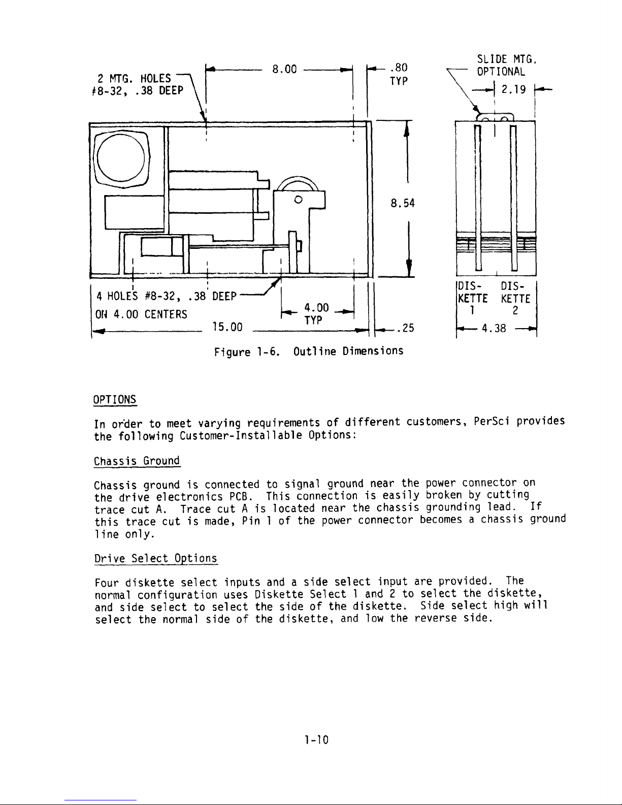
Figure 1-6 . Outline D imensions
OPTIONS
ln ork er to meet varying requïrements of different customers , persc i provides
the follow ing Customer-lnstallable Optîons:
Chassis Ground
Chassi! grcund is bcnnected tc signal grqund near the power ccnnector on
the drlve electronlcs PCB . This connectpon îs easily broken by cutting
trace cut A . Trace cut A îs located near the chassis ground inj lead . If
this trace cut is made , P 1n 1 of the power connec tor become s a chassis ground
line only .
Drive S elec
-
t Options
Fcur d iskette select inputs and a side select input are provided . T he
normal configurat icn uses Diskette Se lect 1 and 2 to select the d iskette .
and side se lect to select the side o f the diskette . Side se lect high w ill
select the normal side of the d iskette . and 10W the reverse side .
1-10
Page 17
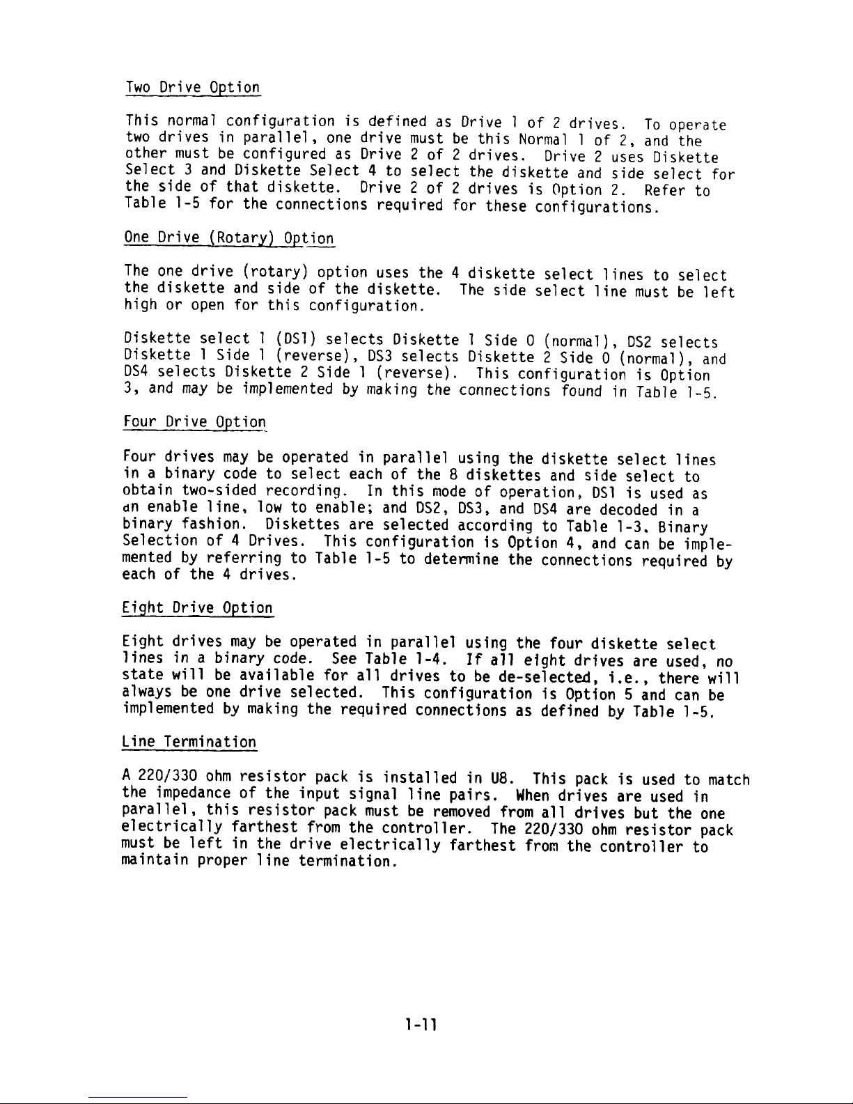
Two Drive Option
Th is nc rma l conf igura tïon is de fïned as Dr ive 1 o f 2 dr ïves
.
To ope ra te
two dr ives in parallel , one drive must be this No rma l 1 o f 2
, a nd the
other m ust be c on figured a s Drive 2 of 2 d rives . Dr ive 2 uses oiskette
Selec t 3 and D iskette Sele ct 4 to se lect the d ïske tte a nd s ide se lec t f0r
the side Gf that diskette . Drive 2 of 2 d rives is option 2
. Re fer to
Tab le 1-5 for the connections regu ired for these configura tions
.
One Drive (Rotary) Option
The one drive (rotary) option uses the 4 diskette select lines to select
the d iskette and s ide of the d iskette . The side se lect line m ust be le ft
hig h o r open for th is co nfigura tion .
Diskette select 1 (DS1) selects Diskette 1 Side 0 (normal), DS2 selects
Diskette 1 Side 1 (reverse), DS3 selects Diskette 2 Side 0 (normal)! and
DSô selects Diskette 2 Side 1 (reverse). This configuration is Optlûn
3 , and may be im pleme nted by ma klng the connect bons found Jn Table 1
-
5 .
Four Drive Option
Four drives may be operated in parallel using the diskette select linesi
n a binary code to se lect each of the 8 d iskettes and slde se lect to
obta in two-sided record ing . ln this mode cf operation , DS1 is u sed as
un enable line . 1ow to enable ; and DS2 , DS3 . and DS4 are decoded ln a
binary fashion . Diskettes are selected according tn Table 1-3
.
Bina ry
Selection nf 4 Drives. This confisuratinn is option 4 . and can be im ple-
mented by referring to Table 1-5 to determine the connections required by
each o f the 4 d rives .
Eight Drtve Opt
-i-
o n
Eight d rives m ay be operated in para llel usic: the four d iskette select
lines in a b inary code . See Table 1-4 . If a 11 e fght dr fves are used
.
n o
state will be available f0r a11 d rives to be de-selected
.
i.e ., there w i11
alway s be one drive selected . This conflguratbon ls optson 5 and can be
implemented by making the requ ired connectfons as defined by Table 1-5
.
Line Term ination
A 220/330 chm resistor pack is iqstalled in U8. This kûck is used to match
the impedance of the input sijnal line pairs. Mhen drlves are used ln
parallel , this resistor pack must be removed from a11 drives but the 0ne
electrically farthest from the controller. The 220/330 ohm resistor pack
must be left in the drive electrically farthest from the controller to
maintain proper line term inat ion .
1-11
Page 18
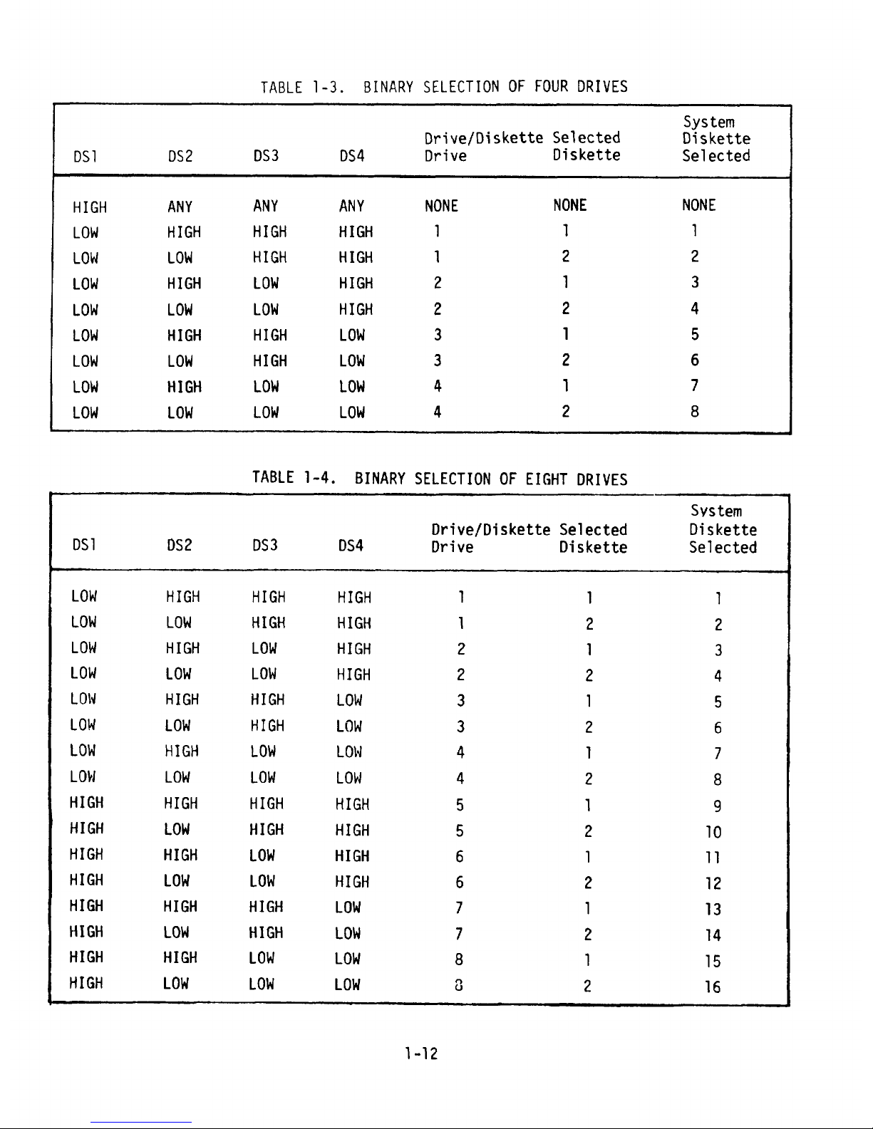
TABLE 1-3 . BINARY SSLECT ION 0 F FOUR DRIVES
System
Drjve/Diskette Sllected Dqskette
DS l DS2 DS3 DS4 Dr lve Dlskette Se lected
HIGH ANY ANY ANY NONE hONE NONE
L0H H IGH H IGH H IGH 1 1 1
L0H L0% H IGH H IGH 1 2 2
L0k HIGH L0% H IGH 2 1 3
L0H L0k L0% HIGH 2 2 4
L0% HIGH H IGH L0% 3 1 5
L0H L0H H IGH L0% 3 2 6
L0k H IGH L0k L0% 4 1 7
L0M L0H L0H L0H 4 2 8
TA BLE 1-4 . BINARY SELECT ION 0F EIGHT DR IVES
Svstem
orive/Diskette Selected Diskette
DS 1 :S2 DS3 DS4 pr ive Diskette Selected
L0H H IGH H IGH H IGH 1 1 1
L0H L0H HIGH H IGH 1 2 2
L0H H IGH L0H H IGH 2 1 3
L0H t0% L0% H IGH 2 2 4
L0N H IGH H IGH L0H 3 1 5
L0H L0H H IGH L0H 3 2 6
LO% H IGH L0% L0l4 4 1 7
L0H L0M L0H L0H 4 2 8
H IGH H IGH H IGH H IGH 5 1 9
H IGB L0H H IGH HIGH 5 2 10
H IGH H IGH L0% H IGH 6 1 11
HIGH L0: L0: HIGB 6 2 12
H IGH H IGH H IGH L0% 7 1 13
H IGH L0% B IGH L0% 7 2 14
HIGH H IGH L0M L0H 8 1 15
HIGH L0M L0% L0H 0 2 16
1-12
Page 19

He ad Load
The noçm al co nf7gurat qon ls suc h that if a diskette is selected . the heads
are loaded . Head load input , P in 16 . serve s as an OR funct ion w ith select ;
th ls lnput may be used to lo ad the heads of the non -selec ted dr ives in
antlclpatlon of read/wrïte activïty . The normal connection utilizes a
75451 ln the U26 qosition. Head unload ls delayed approximately 5 seconds
for accessin: varlous diskettes without W ait ing fcr head 7oad when the
Se lec t comes bac k to the orïg ina l head .
Optbona lly , the 754 51 can be removed from U26 and a 75453 installed . This
makes head load an AND function With diskette select, allowing ready, index
two -sided and write protect funct ion s of a selec ted drive to be m on ltored
w ithout load ing the heads . This is Opt ion 6 .
lndex/sector
The drive norma lly com es from the facto ry w ired to prcduce a 1 ms pulse
from h lgh to 1ow logic leve l at Pins 8 and 20 each t ime an index or sector
hole is sensed on the selected dJskette . Refer to Table 1-5 for the connec-
tions o f th is implemen tat ion .
Independent Index/sector Lines
Optjon 10 allows independent monitoring Qf index/sectors from each diskette
of a drive. Pin 20 will have index/sector pulses from Diskette 1 and Pin 8
wil) have index/sector pulses from Diskette 2 . When either diskette is
selected . This option may be configured by m akin: the connect ion s found
ïn Table 1-5 .
Sepa ra ted Index and Sectors
Opticns 11 . 12 . and 13 prov ide for separatinq the index pulse from the
sector pulses on a hard sector d iskette . 32 . 16 . or 8 sectors can be pro-
vided . The lndex pulse appears on p in 8 wh ile the sector pulse s appear
on Pin 20 of the I/0 connector . -
lm plementat ion is accomplîshed by making the connection s listed in T able
1-5 .
Although only the selected diskette 's index and sectors are availab le .
sepa ratlon and countdown are ma întained for both d iskettes to prevent
loss o f synchro nizat ion for an unse lec ted d iskette .
Diskette Eject
The Model 2998 comes from the factory confijured such that diskettes may
be ejected (whenever write gate is false) elther by a nushbutton switch
at the bezel or. (for the selected diskette only) by a 100 ns minimum
pulse o r level to log ic 1ow on the ssgnal interface P in 14 . Refer to
Table 1-5 for connec tion de ta ils of th is configuratlon .
1-13
Page 20
I II()E' ï HOt E
v = 6 . 175 z . 005 ( 1 56 . 8 :!: . l nml ( S INGLF S I DE.D )
x = . 1 50 :t . 005 ( 3 .81 0 :t . 1 mm)
Y = . 200 :!: . 01 0 ( 5. 080 :!: . ?50 mm) INDEï HOLE
( DUAL S I DED )
Z = .075 :f .005 ( : .905 :f . 1 mm) O
Z
HEAD ACCESS
OPEN ING
Y
.
= k > - 't y
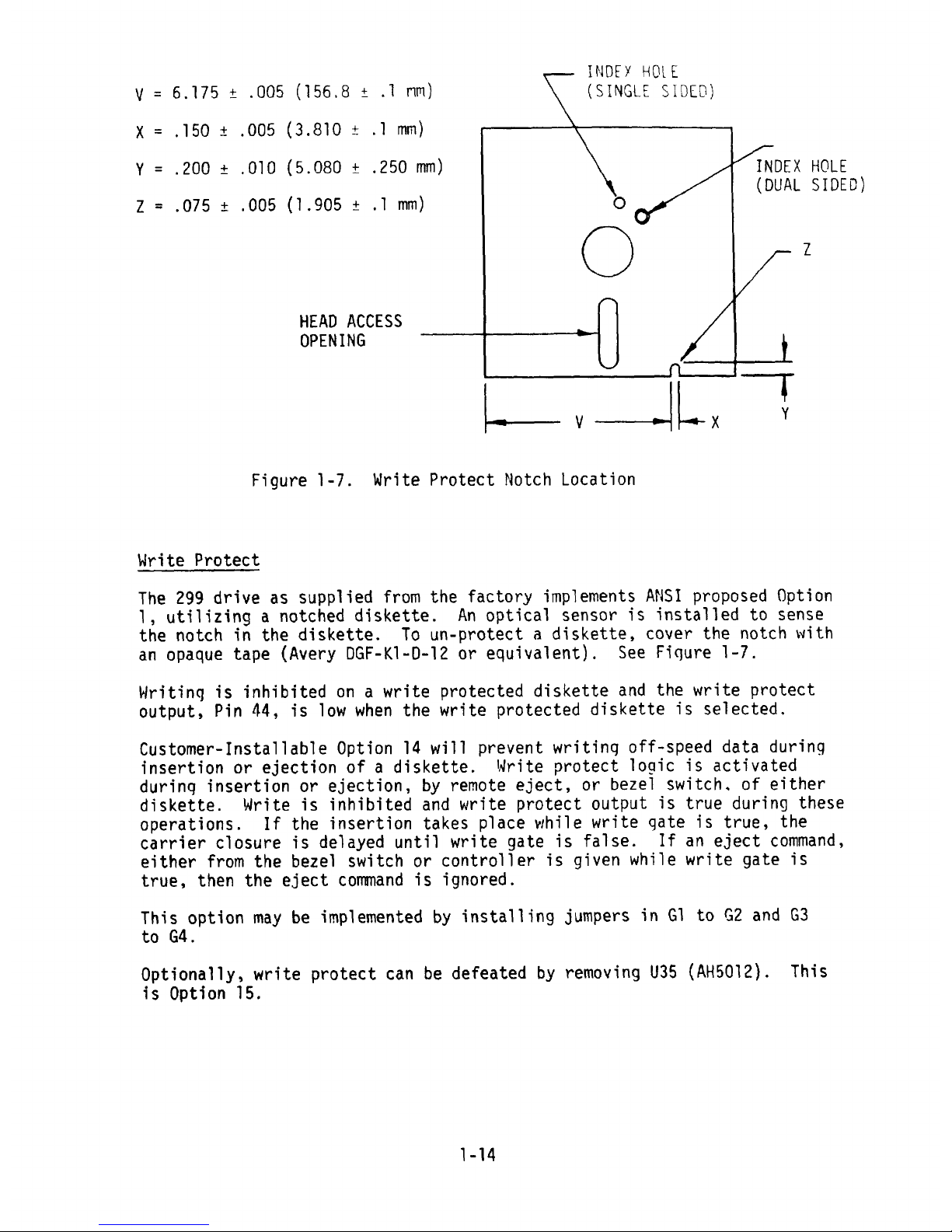
Figure 1-7. Vrite Protect Notch Lccation
kr ite Pro tect
The 299 drive as supplied from the facto ry implements ANS I proposed Optlon
1 , utilizing a nctched d iskette . An optical sensor is installed to sense
the notch in the diske tte . Tc un-prc tect a d iskette s cover the no tc b w ith
an opaque tape (Avery DGF-KI-D-IZ or equivalent). See Fiqure 1-7.
Hritinq is inhibited on a w rite protected diskette and the w rite protect
output . Pin 44 , îs 1ow when the w rite pro tected diskette is selected .
Cu stomer- lnstallable Opt ion 14 Will prevent writlng o ff-speed data dur ing
însertion or ejection of a diskette. lkrite protect logic is actîvated
durinq insertion or ejection, by remote eject, or bezel switch. of eîther
d iskette . Hrite is inhib ited and Wr ite protec t output ls true turinj these
operat ion s. lf the insert ion takes place w hile W rite qate is true , the
carrier closure Js depayed until write gate is false. lf an eject command,
either from the bezel sw itch or controller is gqven wh ile w rite gate is
true, then the eject coFmand is ignored.
This option may be implemented by installing jumpers in G1 to G2 and G3
to G4 .
Optionally, write protect can be defeated by removing U35 (AH5072). This
is Optlon 15 .
1-14
Page 21

Hanual Eject lnhibit
Optîon 9 is the manual eject inhiblt option. Rith this configuration a
logic 1ow on Pin 30 of the signal înterface will prevent ejecticn by the
bezel pushbutton ; allow ing the controlle r to loc k in a d iskette until
reat/write operatjons in prcgress (i.e., closing files) are complete.
Refer to Tab le 1-5 for con nection deta ils .
Diskette Eject Request
Hhen Opt ion 8 is configured : the function of the bezel pu shbutton is
changed from ejecting the dlskette to prcducin: a logic 1ow at Pin 30.
The controller can then recognize this signal and issue an eject command
when a11 processinj is finished . Re fer to Table 1-5 for connection deta ils .
Data Sepa rat ion
The 2998 c an be ordered W ith no data se parator . or w ith FM data sepa rator ;
or with HFM/MZ FM data separator installed
.
Fh1 Data Se pa rato r
The FH data Separator use s a p hase loc ked loop techn ique to pro pe rly sep-
arate clock and data pulses from the FH (double frequency) code. Proper
se parat ion is ma inta ined over th e three dropped c locks o f an IBH type
address m ark . Separated data and separated clock pulses are sycchron ized
to the phase loc ked loop. Froper separation is : data pulses alway s on the
data l ine and clock pu lses a lway s on the c loc k line . Sep arated data is
?in 48 and se parated cloc k P in 50 of the signal interface connec tor .
0ne Shot Emu lat ion
To funct ion pro per ly in con trolle rs de signed to opera te w ith one shot data
separators the phase locked data separator can be jumpered such that the
cloc k pu lses w ill appear on the d ata line , and data pul ses on the cloc k
line ! after the first m issing cloc k o f an IBH type addre ss mark . Th is
condltion continues until the first misslng data qulse of the address mark;
at w hich time cloc k and data pulse s appear on the lr proper l ine s . Phase
locked tracking and synchron izat ion of data is ma ïnta ined While emulating
one sho t ty pe t iming . Cut Trace A to C and install Jum per B to C on the
data separator to implement this o pt ion .
phase Locked Clocq
The single den sîty data separator provides a 250 KHz square w ave phase
loc ked to the incom ing d ata . T his signa l is pos itive go in; at the lead ing
edge of separated data and negat ive go ïng at the le ad ing edge of separated
cloc k pulses . Except w hen the loop is acquiring lock there are no m issing
pulse s on this signal , T his signal m ay be used for very simple address
mar k de tect ion and da ta serial to para llel conversïo n . To obtaïn this
output J um per B3 to B1 on the dr ive e lectron ics PCB . The phase locked
cloc k output is Fin 32 of the sîgna l interface connector .
1-15
Page 22

MFM/H2FH Data separation
A data sepa rator is ava ilab le wh ich may be used for both of these codes .
A pulse appears cn the separated data l ine . Pin 48 of the signal interface ,
for each data pu lse in the cnde . These pulse s are synchron #zed to the phase
locked loop such that timing jbtter due to density effects is fîltered.
A reccnstructed c loc k derived from the phase locked loop appears on the
separated c lock line , Pin 50 o f the sîgnal in terface connec tor .
The HFH/M2FM data separatcr reguires a synchronizing pulse at the beginning
of eac h field independently w ritten on the d isk . In a hard sectored system
where sec tors are separated and co unted in the 2998 : Jum perïng B3 to B4
w ill prc vide this . o the rw ise , Jumpering B3 to B2 w 171 connect the sync
line to Pin 24 of the s igna l inter face connector .
FH Data Separator Adjustment
The FH data separator was adjusted at the factory. and normally needs no
maintenance. The only adjustment is the VC0 center frequency. This may
be adjusted wîth potentiometer R-12. Adjust while installed usinq the
fo llow in g proced ure :
1. Observe the sawtooth VC0 at T?1 (Approxïmately 4.4V p-p). Observe the
kC0 control koltage (range +0.4V to -0.4V) at T?2. The oscilloscope
sround s m ay ba connecte d to TP5 or T P6 .
2. Hrîte a dîsk using either a 4998 exerciser (STD. pattern) or the host
system for the drlve. (An a11 0's FH pattern gives least phase Jltter.)
Read this d isk fo r data input to the data separato r.
3. Adjust R12 until the system locks the saWt0oth to read data with the
sawtooth at Approximately 500 KHz. (Actual frequency is determined
by data frequency , : 2% average.)
4. Sontînue to adjust R12 such that the average value at TP2 is 0k t 50 mv
while locked at 500 KHz . rlote that ISV W ill cause this voltage to
oscillate about qround as the loo p tracks drive spee d .
MFM/MZFH Data Separator Adjustment
The MFM/HZFM data separator was adjusted at the factory o it normally requires
no malntenance. There are three adjustments; sync pulse. frequency, and
phase .
Sync pulse 7s adjusted With 229, frequency with Rl6, and phase With R4.
Adgust w ith the fo llow ing procedure W ith da ta separato r insta lled .
1. Prepare a disk of al1 0's using either a 4998 exercîser OIFM pattern)
or the ho st sy stem . Read this disk fo r da ta to the da ta separa tor .
1-16
Page 23

2 . Adgust the sy nc pulse at T ?8 to 2 5 0 pseconds us ïng R?9 . If necessary ,
trlgjer this pulse by temporarily Jumpering B3-B4 on the drive elec-
tronlcs PCB. (0r jumpering Pin 24 to Pin 20 at the signal interface
connector.) This is a negatsve golng TTL level pulse.
3 . O bserve the VC0 saw tooth at TP3 and the kC0 co ntrc l vo lta ge at T P2 .
Oscilloscope jround is available at T?1. Adjust R16 to lock the VC0
to the data Wpth the VC0 at 1 NHz. Continue to adjust R16 to center
the VC0 control voltage about ground (â 50 mk) while maintaining lock
at 1 HHz .
4. Observe the read data pulse at TP7 and the data/clock window at TP6 .
Adg ust the pba se contro l , R4 ! to cente r the tra iling edge of the read
data pu lse between the po sitlve go ïng edge and negatlve qo lng ed qe of
the data/clock window . Attempt to make this average setting within
à 20 n seco nd s .
Doub le Dens îty Data Compensat jon
The 2998 comes supplied from the factory to read 'IFN or M? Fn coted diskettes
that are w rjtten w ïthout w rite precompensation . The read electron ics may be
mod ified for optimum perfo rmance , when used w ith diskettes written y ith
Write precom pensation s by configuring Optîon 416 . Refer to Table 1-5 fo r this
con nec t pon .
Conflguration of O pt ions
ln the following table, the items listed unded ''Connectinns'' are jumqer
point s or 1C 's located on the drive electronics PC8 . IC 's are identlfied
by a ''U'' number and ''Type'' number. The jumper points listed affect the
particular function in that section only . An ''*'' under the jumper points
indicates that an ''ETSHED'' jumper exists and must be cut to produce an
open cond it ïon .
A ''J'' under a jumper point means that the tWo points HUST by jumpered,
An ''0'. means that the two points HUST be open. IC's will be fqllowed by
USE o r Oh11T . T hese cond it ions MUST be m et for any of the conflguration s
to func t ion pro pe rly .
1-77
Page 24

TAB LE 1-5 .
OPT ION COMPON ENTS , JUHPERS , AND T RA CE CUTS
FUNCT ION OPT ION # CON FIGURAT ION CONNECT ION
SELECT cl C3 c4 c 5 c7 c9 C 11
T0 T0 T0 T0 TO T0 T0
C2 64 C5 C6 C8 C 10 C 12
* * * * *
NO RMAL D R IVE 1 0F 2 0 J 0 J J J J
2 DRIVE 2 OF 2 J J 0 d J J 0
**3 1 DRIVE/NO SS J J 0 J J J J
4 4 DRIVES/8 -- -- -- -- -- -- -- X
DISKETTES
4-1 DR IVE 1 OF 4 J 0 J O J 0 O
4-2 DR IVE 2 0F 4 0 0 J 0 J O J
4-3 DR IVE 3 O F 4 J 0 J 0 J 0 J
4-4 DR IVE 4 0F 4 0 0 J 0 J J 0
5 8 9R1VES/16 '
DISKET T ES -- -- -- - - -- -- --
5-1 DRIVE 1 0 F 8 J 0 J 0 J 0 0
5-2 DRIVE 2 0F 8 0 0 J 0 J 0 J
**A lsc known a s ro tary select
.
Page 25

TABLE 1-5 .
OPTION COHPONENTS, JUHPERS, AND TRACE CUTS (Continued)
FUNCT ION OPTION # CONFIGURAT ION CONNECT ION
SELECT C1 C3 C4 C5 C7 C9 C11
T0 T0 T0 T9 T0 T0 T0
C2 C4 C5 C6 C8 C10 C12
* * * * *
5-3 DR IVE 3 0F 8 0 0 J 0 J 0 J
5-4 DR IVE 4 OF 8 0 0 0 0 J J 0
J5
-
5 DRIVE 5 OF 8 J 0 J 0 0 0 0
5-6 DRIVE 6 O F 8 0 0 J 0 0 0 J
5-7 DR IVE 7 OF 8 J 0 0 0 0 0 J
5-8 DR IVE 8 O F 8 0 0 J 0 0 0 0
HEAD NO RHA L DISKETTE SELECT OR
LOAD HEAD LOAD 1/0 U26 = 75451
6 D ISKETTE SELECT
AND HEAD LOAD I/0 U26 = 75453
Page 26

TABLE 1-5 .
OPTION COMPONENTS, JUHPERS, AND TRACE CUTS (Continued)
FUNCT ION OPT ION # CONFIGURAT ION CONNECT ION
D IS KETT E
EJ ECT D1 D3 D5 D7 U2? U2 3 U28
)5454 yy45y75453T0 T0 T0 T0
D2 94 D6 D8
* * * * *
NORHAL BEZEL SH ITCH J J J J OH IT OH IT USE
OR REMOT E EJECT
7 8 EZE L SM ITCH ONLY
OMIT OHIT 0H1T X(N0 REMOTE) J J J J
8 EJECT REOUEST 0 J J 0 USE 0H1T USE
9 EJ ECT INH IBIT J 0 0 J 0H 1T USE USE
Page 27

TAB LE 1-5 .
OPTION COMPONENTS, JUHPERS. AND TRACE CUTS (Continued)
FUN CT ION OPT ION CONFIGURAT ION CONNECT ION
INDEX/ SIDE 1 S IDE 2
SECTORS A2 A 1 A 5 A4 A7 A 9 A7 A9 B 5 E1 E3 C C U2 U3
7474 7474T0 T0 T 0 T0 T0 T0 T0 TO T0 T0 T0 T0 T0
A3 A3 A6 A6 A8 A10 A 10 A11 B6 E2 E4 -- --
+ * * * * *G WG
NORMAL COHHON I/O J 0 J 0 J J 0 0 J 0 0 J - G J - G OMIT OHIT
10 INDEPENDENT I/O 0 J 0 J 0 0 J J 0 0 0 J - G J - G 0H 1T OH IT
11 32-SECT0R5 J 0 J 0 J J 0 0 0 J J J - 32 J - 32 OMIT 0M1T ç
(SEPARATED) '=
12 I6-S ECTO RS J 0 J 0 J J 0 0 0 J J J - 16 J - 16 0!1lT USE
(SEPARATED)
13 8-SECTORS J 0 J 0 J J 0 0 0 J J J - 3 J - 8 US E USE
(SEPARATED)
HR ITE G) yg Ga G a Tg G4 r 3 s
.
A: 50)2PROTECT
NORMAL M R ITF PROT ECT 0 0 US6
F0 R SEL ECT DISK
14 MR ITE FROT ECT J J USE
NORMA L PL U S
DU R ING EJECT
IS N0 H RITE -- -- OM IT
PROTEST
Page 28

TA B LE 1-5 .
OPTION COHPONENTS, JUHPERS, AND TRACE CUTS (Continued)
FUNCT ION OPTION CONFIGURAT ION CONN ECT ION
DAT A ELEST RON ICS H1 T0 H2 H3 T0 H4
CO H P ENSA T ION +
NORHAL USE RITH %; HRITE J 0
PRECOHPENSAT ION
16 USE H ITH : RITE 0 J
PRECOHPENSAT ION
DOU8LE DENS IT? B3 T0 B 2 B3 T0 B4
DATA S EPARATOR NORHAL EXTERNAL SYNC J 0
SYNC (SOFT SECTORED) k
.
117 SECTOR SYNC 0 J
(HARD SECTORED)
S ING LE DENS ITY B3 T0 B1
PHASE LO CKE D 18 P
HASE LOC KED CLOC K 0CLOCK
FROH F/M DATA
SEPA RATOR
Page 29

SECT ION 2
HA INTENANCE
This section cnntains the follow ing :
Preventive ma intenance schedule and procedure s.
Maintenance check, adjustment and replacement procedures.
Diskette Dr ive Exerc iser . o pera ting procedures and replacement ,
FREkENT IVE HA INTENANC
-
E
- -
S
- -
CHE
-
DULE
kuarterly Cleaning
a . Cleac inte rior and exter ior surfaces w ith damp c loth using a
solut ion of non-abrasive c leaner . C lean d rive be lt . d rbke and
driven pulley s w ith alcoho l.
b. Cpean positioner scale surfaces using lint-free c10th (dry) and
vîsually exam ine fQ r fore ign partîcles after c leaning . Foreign
pa rt icles on the clear area of the ve loc ity wedges , even m inu te
ones. are part icularly de trimen tal to po sitio ner performance .
c . Clean positioner gu ide ra il with dry . lint-free c 10th .
d. Clean read/write head using alcohol.
Drive System Te st
a . Run available diagnostic test to verify proper operatinn of
d iskette drive .
PREVENT IVE HA INTENANCE FROCEDURES
Spind le D rive Sy stem
a . Remo ve the d rive be lt and engage both cones by manually depressing
Side l and Side 2 load cam shutter . H ith bo th cones engaged . the
dr fve be lt removed . and no med îa pre sent . the hub a ssembly shou ld
rotate virtually frict ïon-free . lf frict ion is detected then
either tbe hub or cone bearings are wo rn . The prob lem c an be
iso lû ted by rcta ting tbe hub se parately s then en gaging the cones
separately .
b . Rotate dr ive mo tor sha ft and check for uniform ity of torque .
A non-un iform rotaticcal torque may be due to worc bearings .
2-7
Page 30

Drive Be lt Tens ion
a . Drive be7t tension ïs measured by applying a side force to the
belt at the center of span between the crowned idler pu lley and
hub and measuring the deflection . place a scale a t the center
of span norma l to the belte Apply a 1 1b . force to the be lt us bng
a cantilever type fcrce jage and measure the resultant belt de-
flection . Belt tension ls correct when the deflection is .1 à
.
02 jnc he s .
Read/krite Data Amplitude
a . Diskette opera tinnal , drive ready .
b. Uslng a new 1BM Diskette 2, write an a11 ones pattern (FH) at
Track 76 . observe read data differentially at TF77 and 18 , ground
scope at T P8 o r TP14 .
c . Output must be at least 200 m v p-p.
d . lf the proper reading cannot be p btained , the possible problem
a r e a s a r e :
1 . Defective w rite drivers.
2 . Defective med ia . Repeat test w ith a d ifferent d iskette to
îso late problem .
3. Defective read/write head.
MA INTENANCE PROCEDURES
The maintenance procedures are divided as follows :
Chec k
Adjustment
Replacem ent
Tools a nd Test Eq uîpm en t
The follow ing material is required to perform the ma lntenance procedure s :
Com mon hand too ls
Fla shligh t
lnspec tion m ir ro r
Cotton-tipped swabs (k-Tips)
95% Iso prophy l alco hol
6-ïnch steel scale, l/loths
0 -1 oz . or 0 -30 gm . fo rce gage
1-1b . fo rce sa je
Al ignmen t Dis kette - DYHE K 80 2-11
Osc illo sco pe , Te ktron lx 465 or eq uîva len t
Drive Exe rc iser - Fersc i Mode l 4998
Kimw ipe s
2-2
Page 31

The cogn izant maintenance personnel should
read the entlre check , adjustment or replace-
ment procedu re prior to pe rform ing the rout ine .
Je
-
cks and Plugs
The interconnectïng plujs and jacks are listed ïn Table 2-1 and fdentifled
in Figure 2-1 . The connector pins should be checked for cleanliness and
tota l co ntac t if interm ittent problem s are encountered .
TAZLE 2-1 . JACKS AND PLUGS
ASSEHBL? CONNECTOR
Drive Elec tronics P1 Customer S ignal Interface
PCB 02 Voice Co il Motor Assem bly
03 DC power lnput
04 Eject and Harness PCB
15 Servo Lam p Assem bly
06 Hask Assemb ly
J7 Data Separator
08 Read Hrite Era se PCB
Read Hrite Erase J1 D iskette 1 Heads
PC8 02 Diskette 2 Heads
J3 Drive Electron ics PCB
Data Separator J 1 Drive Electronîcs FCB
PC8
Eject and Harness J1 Drive Electronics PCB
?CB 1 J2 Dïsektte 1 Eject Motor
J3 Carrier Sw itch 1 , Bezel Switch 1
Ac tivity Light l s lndex Sensor 1
04 Head Load Hechan ism l s Hrite Protect 1
2- 3
Page 32

TABLE 2-1. JACKS AND PLUGS (Continued)
ASSEHBLY CONNECTOR FUNCT ION
Eject and Harness J1 Drive Electronics PCB
PCB 2 J2 Di
skette 2 Eject Hotor
J3 Carrier Switch 2
,
Bezel Sw itch 2
Activity Light 2 , Index Sensor 2
04 Head Load Mechan #sm 2
,
Hr ite P rotec t 2
05 Index Light Sou rce
Deck J4 Sp indle Xo tor AC
Drive Elz ctronics PCB
The diskette electronîcs PCB contains the the customer 's l/0 connector
,DC power inqut connector and most of the electronics. lt also serves as
a d istributlon and gathering po int for a 11 nther sub-assem blies
y e xceptth
e spind le motor .
PCB Re placem ent
a . Disconnect a71 the connectors along the upper board edge
.
b . Rem ove the screw holdîng the lower board etge to the d iskette frame
.and re lease the catch
.
c . Remove three screws hold ing the PCB hinges to the FCB
.
d . Install replacement ?C8 by reverse procedure
.
e . A lignm ent o f re placem en t FCB to low er mount ing po ints is ach seved by
slac ken îng three screws ho lding hînges to PC8
.
Voltage Adjustment
No adjustments are provïded for voltage levels. If any voltage îs out of
tolerance . chec k fcr internal lc ad ing by d isccnnecting d iskette drive and
chec king levels at controlle r
.
If leve ls are co rrec t , check out cable or
iso la te a defect ive compo nent or as sem bly a t the dr ive e lectronics PCB
.If necessary . replace the PCB
.
2-4
Page 33

=
,
q a 'P A5 A4 j
ja2 os
DATA SEPARATOR PCB READ/HRITE HODULE PCB
J 2 J 4 2 5 J l
A l A z
: 3 J3
J I J 2 J4
EJECT AND HARNESS S IDE 1 PC2 EJECT AND HARNESS SIDE 2 PCB
= M =
J : :7 :6 J J# g
J 3
A I
l
lP1
l
l
DRIVE ELECTRON ICS PCB
Figure 2-1. P1Q9s and Jacks ldentificat ion
2-5
Page 34

D R I V E
M Q TQ R
O
5 * +
# 4 -4 0 SO C K Q T H EA D
A OJ U S F M E N T SC R E W
l I l l
'
O t ,! $
/ /
J ?
A
zz
> . . .
M
.
e
. . . .' e
T E N S lO N A D J U S T
ID t E 9
Figure 2-2 . Dr lve Sy stem
Dr îve Motor and Belt Cbecks
a. Set d iske tte power off .
b . Inspect d rive be lt fo r wear , pa rt icularly fray ing of the ed ges .
c . Hanua lly rotate dr ive m oto r. lf b ind ing is ev ident , re place moto r.
d . Verify belt ten sion .
e . Verify drive belt tracks in center o f both d rive and d riven pulley s ;
retrac k be lt if necessary .
Drive Belt Tension Adjustment
To adjust drive belt tension, proceed as follow:
a . Set d iskette power o ff.
b. Loosen idler shaft screw. (Figure 2-2.)
c . Slide id ler shaft away from d rive mo tor so as to tension be lt .
d . T ighten idler shaft screw and check belt tens ion .
e . Belt tension is correct when the belt deflect ion at the center of
span ls .1 à .02 inche s .
2-6
Page 35

Drlve selt Replacement
a . Se t d iskette powe r off .
b . Slac ken id ler pul ley shaft screw and slide shaft tcwards drive mo to r.
c . Remo ve m o to r .
d . Remove belt .
e . Clean mo tor and spind le pulley surfaces , w ipïng spar ing ly w ith alcoho l .
f. Install replacement belt and motor , carefully placing belt around moto r
pulley .
ç . Re -tens ion belt .
Ind ex T ransd ucer and Loqic Checks
The procedure for checkinç index transducer is the same for Side 1 as Side
2 . only the te st points and potentiometer s used are d ifferent .
a . Se t d isket te pow er on .
b . If the drive is of ''norma l'' configurat ion as defined in the options
sec tion , a 1 ms à 15% pulse occurring once each 166 .7 m s 1 2% w ill
occur at Pin 8 and Pin 20 w hen a ''soft sector'' d iskette is inse rted
and se lected. Check with Diskette 1 selected and w îth D iskette 2
selected . For both sides, check that extra pulses do not occur When
a d iskette is inserted . Chec k that pulses do n0t occer when the selected
diskette is removed (both sides). lf optional interfaces are used
refer to the options section to determine index/sector output character-
istics .
If the drive is beîng used as a soft sectored driye. only Steps a and b
above are requ ired . The follow ing steps are regulred only lf the drive
is to be used in a hard secto red env ironment .
c . Index transducer al ignment is c hec ked usïng a DYHEK 802 -11 a lignment
d iskette . Fo r its u se read the procedure sh ipped With each d iskette .
Determ ine if the drive is being used w ith single sided Qr two sided
tiskettes . If used w ith single sided d iskette . cover the index hole
furthest from d iskette center line w ith a write protect tab or an cpaque
tape . If it is to be used w ith a tw0 sided diskette . cover the m iddle
index hole . If both ty pe s o f d iskettes are to be used the al bgnment
must be perform ed each way .
d . Insert DYMEK alignment Diskette 802-11 into S ide 1.
e . Access Track 73 and load head assembly S ide 1 and select Head 1.
f. Monïtor read data at TP13 on the d rïve e lectron ics board ground ïng
the probe at T P14 ,
2-7
Page 36

g . Sy nc to lead inj edg e c f lndex qu lse a t ? in 20 o f 81 o n the dr lve elec -
tro nic s board .
PROG : INDEX TRANS DUCER
SYhC : EXT CH 2 NEG
CH 1 : .SV/DIV A .C .
NODE : CH 1 50 gSEC .
h. T he sta rt of the data burst should 1a9 t he ne ga tive go ing edge of the
inde x pu lse by 2O0 psec à 100 psec .
- - - - - . - . - - - - -
,
I jj' ' ' I t ' II
I
il
- .e. 1* ,1 j , j ,' j sc v s Ec/nl v
1 t. I
Figure 2-3 . Index Fulse and Data Burst
i. T hss is true for bo th T rack 73 and T rack 1 . Any d qffere nce ln reading
between these two tracks is due to machîne az imut h ; az im uth should
be checked before aligning the îrdex transducer .
j. Variaticns in reading will occur with successive insertions of the
diskette and an average read lnq shou ld be taken . Excessive var lations
w ith d iske tte inse rt ion , i .e ., greate r than 1 50 p sec , indica te a
med ia concentric ity or registration problem . lf this occurs , perform
the spindle cone check outlined on page 2-10 . T he timlng should remain
be tween 1 0 0 p sec and 30 0 gsec fo r a11 ca se s .
k. T o chec k index Side 2 load DtHEK alignm ent d iskette into S ide 2 and
select Bead 3. Leave scope probe at T?13 and repeat Steps e thru j.
Index Transduce r Alignment
This alignment is n0t required for dr
-
ive s u sed in soft sector env ironment .
To align the index-rransducer , sync from lead ing edge of index pulse and
monitor data burst on the DYHEK alignm ent dîskette 802-11 as described
in the index tra nsducer check procedure .
a . Alternately access Tracks 1 and 73 .
b. Observe time inte rval between negatïve edge of index pulse and data
burst .
2-8
Page 37

c. Adjust R4 until time interval is 200 : lû 0 psec fcr siqgle slded disk-
ettes . and R8 until t ime interva l is 200 : 1 o o psec for two sided d isk-
ette adjustment at Track 1. (Use R12 and q15 for Sfde 2 adjustments.)
Verbfy that it is 200 zl 00 psec at Track 73 .
d . Chec k w ith successive insertions of diskette that time interval remains
200 à l o û gsec at Track 7 .
e . lf this time interva) cannot be achieved by adjustment of the photo-
sense electronics . then prcceed as fcllow s:
1 . Po siticn the phcto sen se as c lose to the correct po sition w ithout
losing sijnal .
2 . Remcve d iskette .
3 . Hanually load the cone by pressinq the carrier in and observe the
alignment between the photosense and lamp modupe .
4 . Slacken two screws holdin: photnsense assembly to deck plate and
reposltion sach that the photosecse and lamp :re cpposite each
othe r .
5 . Insert d lskette and proceed w ith alignment frcm Step ; .
Index Transduce r Rep lacement
The ïnde x transducer consbsts o f two elem ents - the photosense assem bly
ant a common lam p assem bly .
Tc replace the photosen se assembly proceed as follow s :
a . Set d iske tte powe r off .
b . Unsolder the yellow . blue . and green lead s at the pho tosense assembly
observing lead pnlarity .
c . Remove Nc . 4 allen cap screws Securing photosense assem bly to carrier
and insta ll replacem ent a ssembly .
d . Snlder lead s, observing same polarbty as on the replaced assembly .
e . Perform index al ignment procedure .
To replace the lam p assembly proceed as follow s ;
a. Disconnect P5 from eject and harness PCB 2.
b . Remove two screw s securing lamp assembly to deck plqte . beiog careful
n0t to d ïsturb lens al ignment .
c . Remo ve lamp assembly and insta ll replacemen t assem bly .
d . Check ind ex aljgnment .
2-9
Page 38

l l F 1 1 R j N g
(3 PLACES) '
SHAFT
j2 pH0T0sENsE
CARRIER , '' ASSEXBLY
' %.9
l
.
09 : .01
. Aqayrq
I CLOSED
%ASHER
- . -
'
I LAMP
THRUST
BEARIN
ASSEPBLY
1
CONE FLANGE I
CONE SPRING
j
CONE
1
I
Figure 2-4 . Index Transducer and Ccne Assembly
Sp indle Cone Check
a . Connec t the Channel 1 scope prcbe to T?l3 on the diskette electron ics
PCB and ground at TP14 and the tr igger probe to ?1-20 . Set the sccpe
controls as follow s :
MODE : CH 1
VOLTS/DIk: 0.2 (10y probes) AC
SECONDS/DIV: 20 mS
TR IGGER SOURCE : EyT
TRIGGER COUPLE ; AC , NORM
TRIGGER SLOPE: (-)
2-10
Page 39

1 p
! , . 1 I
Peaks = 1 .2 V ' ' I
1 I ! '
f
Hndulation s drop ' I
zff to 1.1 vi *- i'
Reference
Peaks = ) .1 V
Mndu lations d op zff
to 1.0 V
1
After Reinserting
Figure 2-5 . Example of Good cone
I.1 = 92% peaks 1 '0 = 9q: yoduqat jons
1.2 1 .7
b. Insert an 1BN D iskette 1 or D iskette 2 w hich is known to have a good
center hole . position to Track 0 . select Side 1, and write a 1 's pat-
tern and O 's patte rn .
c . Carefu lly notice the am plitude cf the signal and the modulat ion char-
acteristics . Y ou w ill be looking fnr changes in amplitude and modula -
tion charac teristics , so study them before proceed ing .
d. Eject the disk, then reinsert it. D0 N0T HRITE again. Look for lower
amplitude or increased modulat ion . If the am pl itude of the en tire
signal or if any modulation decrea ses by 10% or more . the cone is bad .
Eject then reinsert the dlsk ten times. lf the cone looks bad any
one of the ten times , it 's bad and mu st be replaced .
e . Repeat a thru d for Side 2 .
2-11
Page 40

Sp lndle Cone Replacement
The cone assem bly engages the med ia w ith the drive hub . T he cone a ssem blies
for Slde 1 and Side 2 are the same and the replaceme nt procedures are the
same . To replace the cone o r any o ther part w ith in the assembly , proceed
as follows :
a . Set d iskette power o n .
b. Hanually depress the optical load shutter , thus engag ing the cone with
the hub .
c. Remove E ring holding the cone assembly to the carrier. (Fiçure 2-4.)
d. Press the eject button, i.e., carrier in disengaged pcsition.
e . Remove cone assembly , com pression spring , and shim washer , between the
spring and carrier .
f. D ismantle co ne assem bly by removîng E ring next to the thrust bearing .
g . Install replacement cone and assemble by reverse procedure .
Positioning System
The qositioner servo comprises a voice coil actuator, optical transducers,
carrAage essembly :nd the e7ectroqics requ ired to control the system .
Positioner circuits are located on the drive electronic PCB. (See Figure
2-6.)
Positioner
-
Se rvo Check
Using the osc illosco pe . observe the po sit îon tran sduce r output at T FC .
A signal sw ing of 3 .25 à .25V p-p is expected . Ground the o sc illoscope
at TP2 . Sy nc hron ize the osc illosco pe to the pos itive golng edge of seek
complete , ava ilable at a test point of the 4998 exerc iser or at ?1 ? in
10 s the signal interface connector to the dr ive .
After connecting the osc illo scope , alte rna tely see k between Trac k 00 and
Trac k 76 , us ing the tis ket te drive exerc iser in SL mode . ke rify that each
see k requires 100 ms k 5 ms : that the positioner transducer output is
3 .25 à .25V p-p m inimum durlng see k and that the po sitione r transducer sig-
na1 is balanced w ithin à 100 m t about ground . Observe at 0 .5V per d iv qsion
on the o scîlloscope .
Ste p sequent ially from trac k to trac k w ith the d iskette exerc iser . u sing
step m ode . Ver ify that the posit ioner settqes within O .5 d ivisions within
10 m s , and that there are no overshoots greate r than 0 .5 d ivision s.
(Observe at 0.5% per dbvision.)
See k in crescendo mode ! automatic , w ith t he exerc iser f0r at least two
cycle s to ver ify settl qng to e ach trac k from a h igh speed seek .
2-12
Page 41

Head Assem bly Track A lignmen t and H ac hine Azimuth
a . Se t d is ke tte pow e r on .
b . Lcad DYHEK alisnment d iskette 802-11 into Side 1 .
c . Acce ss Trac k 76 and load head assem bly Side 1.
d . Hon itor read data Head 7 .
PROG : TRACK ALIGNHENT SIDE 1
SYNC: EXT INDEX PULSE NEG. (PIN 20)
CH 1: 50 mV/DIV A.C.
MODE: CH 1. 20 mSEC/DIV
Scope probe CH 1 to TP13 o n data and interface PCB . Hoo k probe
gro und to T Pl4 .
e . lf track alignm ent is perfect the am plîtudes of the cat 's ey e pattern
will be equal. A 30% amplitude difference represents a 1% m i1 position
error. (Figure 2-6 ) 1% mi1 îs the maximum tolerable error.
Machine az imuth is important to , and need nn ly be chec ked for . hard sec tor
dr ive s . De lete tests f, g , h , and ï f0r soft secto r dr ive s.
f. Access Trac k 73 and load head s assembly Side 1 still usinj alignment
diskette . Set up as în ''Index Transducer and Logic Checks'' Fage 2-7 .
g. Observe time bnterval between sync and data burst. (Figure 2-3.)
h . Acc ess Trac k l and observe a ny change in this time interval .
j 1 . dl l '
4
1 j I !
j
l i ! . ' ' j,' 1, /1 I .1J ' ' ' ' '- 1. .! 1 . t
I
l , i li - #( $ j $s , jl
-
r I ,I
I
EkEN AHFLITUDE 100% 0N TRACK 70% AYPLITUDE 1% HIL 0FF TRACK
Figure 2 -6 . Track A lignment
i. If mach ine az imuth is correct the time inte rva l shou ld be the same
with in 100 psec .
2-13
Page 42

HEï S0 C BUTTON HD SCRE: HEX S0C HD CAP SCREHS
4-40 ï 1/4 LG (RECESSED) 4-40 / 1/2 LG
C C
: O
Z
@
HEX S0C HD CAP SCRE%S
4-40 X 5/8 LG
Figure 2-7A . Head A ssem bly Mountîng Screws Side 2
HEX S0C HD CAP SCREHS HEX S0C BUTTON H D SCRE% S
4-40 i 1/2 LG 4-40 X 1/4 LG (RECESSED)1
O O
@ o
o
HEï S0C HD CAP SCREHS
4-40 ï 5/8 LG
Figure 2-7B. Head A ssem bly Hounting Screw s Side 1
2-14
Page 43

20 mS/Dlk DELAtED SHEEP
I
I
l
1 mS/DIV
Figure 2-7C . Cat Eyes and Head Azimuth Display
-
12 M INTUES 0F ANGLE
+)2 MINUTES 0 F ANGLE
0 M INUTES OF A8GLE
Figure 2-7D . Head A zimuth A lijnment
2-15
Page 44

j. Select Side 1 and repeat Steps c throuçh i.
k. Repeat Steps c through j except with the 802-11 alignment diskette ln
Dïskette 1 pnsition and taking the index pulse from Pl Pin 8. (1f
separated index option, take index at Pin 20.)
Positioner Servo Adjustment
lf the positioner servo d id nct pass the check of the preceed inj section ,
alignment m ïght be requïred .
prelimlpary Adjustments
The positioner servo adjustments are located on the drive electronics PCB.
(Figure 2- 8 ) Before perfcrming the preliminary adjustments, unplug P2
from 22 on the drive epectron ics PC8 .
&
e % œ Q : j : 2 . t 1 œœ œ œ œ œ œ = = œ 3 œ œ
N :2
Y 9* 4
i
l
P l 1
TP5 !
rP4 l
T P 1
T P 2 I
T P 5
<Pl4 TP2
TPIS
Flgure 2-8 . Drlve Electronscs PCB
2-16
Page 45

TABLE 2-2 . FOS ITIONEE SERVO FREL IM INARY ADJUSTHENTS
TEST
FU8CT ION CONT ROL PO INT ADJUSTHENT S
Lamp voltage is normally only adjusted on installtion of new lamp. These
two settings are servn cqctrolleö to compensate fcr temperature and age;
they normally vary from lnitial setting - D0 N0T RESET IF OTHER SETTINGS
ARE CORRECT .
Lam p Vo ltage R-28 TP1 Set to 2 .5V à .1V
R-18 T?1 Hove positione r back and forth
over the fu ll stroke and set
R-2 fo r m in imum var iat ion in
lam p vo ltage . Expect to obtain
less than 50 m v var iation over
the stroke . Re set R-28 fc r
2 .54 1 .lV at TPI .
Velocïty R-33 TP3 Adjust for a 1.25k Dc-swinq over
Gain the full stro ke . Should be more
negative toward Track 76 .
Fine R-67, R-68 Tp4 Adjust fcr 3.25V p-p 1 .25V
position balanced about ground as posi-
tioner mo ved back and fo rth by
hand . R-67 is balance and R-68
is ga in .
Track Sense R-72, R-73 TP5 Adjust the bottom of sawtooth
wave form to .0V à .1V at T rac ks
2 through 76 (wi11 be triangle
Wave approximately .5V p-p).
and -1.25k à .1V at Track -1.
N ith servo co il connected , se t
TK 00 voltaçe at .754 A .05V and
ma ke sure the bo ttom o f saw too th
waveforms are st ill at 0k . R-72
is ba lance and R-73 is gain .
Osc ïllo scope TP2
Gro und
Fïnal Adjustments
The adjustments of the preceeding sections should be suffïcient for opera-
tïon , but for attainlng spec ïfied pe rfo rmance levels trac k sense and speed
should be adlusted tynamîcallt. Also. forward and reverse speed is balanced
by adjustinq R-l03 on the posptioner servo FCB.
2-17
Page 46

Move the o sclllo scope probe to TF4 , and oscillo sco pe ground to T?? on the
diskette electronics board. Alternately seek from Track 64 to Track 1.
Stnchronize the oscilloscope to the posltive edge of the ''seek complete''
sljnal found at a test po int on the exe rciser or at P1-10 on the da ta and
înterface PCB. Adjust R-103 for best symmetry between forward and reverse
see ks .
Sync On the negative edge of ''seek complete '' TP on the 4998 exerc iser or
P)-10 of the drive electronics PCB . Alternate seeks between Track 0Q and
Trac k 76 . keeping oscilloscope funct sons as they were , except fo r time .
Adgust R-10 such that the time f0r the longer seek (forward or reverse)
to settle w ithin .25V of ground is 95 to 100 ms . This com pletes the
adjustment of positioner servo.
Mead Assembly Track and Head Azimuth A lignment Sïde 2
a . Use a wr ite grotect labe l o r equ ïvalent to cove r the d ua l sided ïndex
ape rture on a DYHEK 802 -11 alignment d iskette ,
b. Loosen 4 -40 X 1/4 recessed screw holding Side 2 head assembly to carriage.
c . #ccess Track 76 .
d . Insert a lignm ent d iske tte Side 2 .
e . Hon îto r read data at TP13 , using a Te ktronix 465 or equivalent scope
Wh ich has a m ixed sw eep feature . T rigger scope ex te rnal negat lve off
index. Set main time base to 200 msec/div and delayed time base to
1.0 msec/div. Select Head 4 (fixed button bead).
f. Loosen two 4-40 1/2 cap screws holding Side 1 head assembly to carriage.
See Figure 2 -7A .
g . Adg ust assem bly for correct head az imuth . See Figu re 2-7C . Hea d az imuth
is witbin acceptable tole ranc e when the data bursts see n on the delay ed
tïme ba se lnd icate the head is W ith in t 12 m inutes of true position .
How ever , head az imut h interûc ts w ith machine az imuth : the refore ! for
head sector drïves best resu lts are obta ïned by setting head azlm uth
ds close a s fea slb le . Th is gives b est tolerance of param eter var iatio n .
lf necessary , to m eet mach ïne az imuth t ïm ing by cance lling to le rances ,
head azim uth may be re lax ed to à 12 minutes o f arc .
h. Tighten two 4-40 j 1/2 cap screws.
1. Remo ve d iske tte .
J . Tlghten 4-40 X 1/4 recessed screw .
k. Re -insert al ignment d iskette and chec k head az im uth .
2-18
Page 47

1. Adzust track alignment by loosening twc 4-40 cap screws holding the
position transducer to the ma in casting . Rad ial trac k alignment is
correct when the lobes Qf the cat's eyes seen on the main time base
are equa l or w ith in 70: of each other 's am pl itude ,
m . T ighten two 4-40 cap screw s.
IOTE
The posîtion transducer îs used to set rad ïal track alignment 0n
Head 4 only . After this has been set the transducer should n0t be
mo ved .
n . Loosen two 4-40 X 5/8 cap screws holding Head 3 to Head 4 .
o . Mon itor read data qead 3 .
p . lnsert alignment dqskette and access Track 76 .
q. Adjust head for correct ratial track and head azlmuth allqnment.
r. Tighten tw0 4 -40 ï 5/8 cap screws and check alignments.
Head Assem bly Track and Head Azimuth Aliç nm
-
ent
-
s
-
ide 1
8OTE
Side 2 head assem bly must be properly aligned before Side 1 can be
al igned .
The procedure for alignment is the same as Side 1 except thit radial a7ign-
ment of Head 1 (fixed button head) ïs accomplished by movlng the assembly
rad ially rather than movîng the transducer assembly .
Load Cam Shutter Al ign
-
m en t
a . Set d iskette power on .
b . Hanually depress the load cam shutter to allow the carrïer to c lose .
c . Depress the elect button on the bezel to allow the carr ier to open .
d . Observe how the pin frcm the top o f the shu tter r ide s on ûnd com es
to rest on the motor cam w hen the carrier is fully open .
e . The shu tte r pin should be parallel to the flat on the cam , în this open
posïtion. (See Figure 2- 9.)
f . Loosen the 4-40 sictted sc rew on the bo ttom of the casting and near the
fro nt of the egect and harness PCB . p ivct t he board in o r o ut sl ightly
to adgust the shu tter to cam t ïm ïng . Re-t ighten the 4-40 screw to secure
the PCB .
q. Repeat Steps b through e to check the adjustment.
2-19
Page 48

P I N
S H U T TER C A M
#
I !I
,
C R E W PC O4
-
4 0 S
Figure 2-9 . Load Cam Shutter Alignment
Eject Motor C
-
a m
.
A1 ignment
- .
chec k
a . Se t d is kette power o n .
b. Hanua lly depress the load cam shutte r.
c . Observe the crank cam moves to a bottom dead center position relative
to the carr ier plane , i .e ., maximum pene trat ion o f cone assemb ly into
hub. (See F igu r e 2- 1 0B .)
d. Depress eject button on bezel and observe the crank cam rotate to a point
where the bearlnç follower is just clear of impactqng the carrier plane ,
i.e ., 0 - .03.'. Once the carrier is open there must be no further contact
between the bearing follower and carrier. (See Fig ure 2-l0A .)
T h i s c h e c k d o e s n o t a p p l y to d r lv e s w i th S .N . a b o v e 5 35 0 0 .
C ra n k C a m A l ig n m ên t C h ec k
T h e c ra n k c am a n g u l a r a l lg nm en t i s d e te rm i na t ed by th e m o to r
c am a l i g nm en t . T o c h e c k f o r c am p e n e t ra ti o n p r o c e e d a s
f o l l ow s :
a . S e t d i s ke t te p ow e r o n .
b . M an u a l l y d e p r e s s t h e l o a d c am sh u t t e r .
c . O b s e rv e t h e g a p b e tw e en t h e E r in g w h lc h h o l d s t h e c o n e
a s sem b ly t o th e c a rr i e r a n d th e c o rr e s p on d in g c a rr i e r
surfac e . (See Figu re 2- 11 .)
d . W i t h th e c a rr i e r in th e l o a d e d p o s i t io n th e g a p s h o u l d
b e .0 3 5 ï .û 0 1 5 œ .
2-20
Page 49

Cran k Cam Al ignment Prccedure
-
a . Slac ken two Nc . 8 slntted screws securing motor bracke t to deck cast-
ing flange .
b. Set d iskette power on .
c . Manually depress the load cam shutter and observe 9ap described in
Paragraph c nf check procedure .
d . lf incorrect , slacken two N0 . 4 slotted screws holding motor shaft sup-
port to deck casting flange .
e . Displace arm . tighten screw s and cieck alignment .
f. Repeat until desired alignment is achieved .
g . T ighten 2 motor brac ket screw s a fte r al ign ins support arm .
h . After align ing the crank cam chec k the space betweec the phctc seq se
assembly on the carrier and the lamp assembly on the deck plate . H ith
the carrier in the loaded position this should be .09 à .01'% lFigure
2-4.) There is no adjustment for this. If the dimension is incorrect,
deform the carrier sheet metal between the cone and photo sen se assembly .
CRANK CAH
O
0- .030
O
Figure 2-10A. Eject Mntor Cam Alïgnment Check-careier Open
CRAN: CAY
O o
CONE
Figure 2-108. Eject Hotor Cam Alignment Check-carrier Closed
2-21
Page 50

* 4 A O JU S T M E N T C RA N K c A M
S c R ew s .035 !: .045
.
, . q jx G
CA R RIER
) - y. E uo4:En
X.
!
? o $ cAaRjsR
C A S TIN G
r
k
* 8 M O TO R
B U B
> A C K E T
1 c9 Ew S
CO N E A SS EM B LY
Figare 2-11, Crank Cam A lignment Check
DISKETTE DR IkE E/ERCISSR
Malntenance checks and adjustment prccedqres cen be accomplished on-llne
using the controller of off-line usln: the Môdel 4998 Diskette Drive
Exerciser. (See Figure 2-11.)
Contro ls , Ind bcators . and Test Pcints
The exerciser contrcls , indicatcrs , and test po ints are described ïn
Table 2-3 .
2-22
Page 51

e- - T R M K Y : IT
. .#1 N1< Tisl polNlGO S
TEF a a -'* z -'-'''-'''VW - O O
71 2'o 2 7; a wv : x ka r
jx
r
. tx qk m p -N T j sl- t sdtw288 ZSR 2:% r ''-CRER e EX >* T - - C- 6Ti -$* * %W * z4v
N FAST > oj j j xt.ow >%. ' * @k *' G * * * Q?
e 64 Qè GRP/YD
(è) Cd % * @ @ * @
> TA co N T'u
kœ ----= - -''-- u - -'''v u :x z sjprw .jx y o yqx va v . ww . :
' - H * @ 4 ? l Rie t 12'C R W EM * G ' ER E
rxl
c- - - - œ a a'he'- x - - - - - a txt ttlre ,- r to c t
(.=
() u x fx: oOo Oo Oo Oo C)o Cpd Oo () )
w a , , c o . , ;0 . - - - - - - - a- > . : * z 1
s o - r f!v -''''-'''''- ''--w .
o% a I r 1%-
'-- --% &w M- To :+, Lnaztwuœts sl-e -&$ T**të IMM= ' ---= x r *.U 1 - e 1 (t ) 'J
,
()u--- ' w/o * * 00 00 00 Qo 00 00 00 O ' * '
e > * : * ' l
2 2 1 - v r '%e o
o o o o . oo o o o
Figure 2- 12 . Contro l Fane l , D iskette Exerc iser s Hode l 499
Page 52

TABLE 2-3 . E/ERC ISER SM ITCH , IND ICATOR AND TEST F0 lNT FUNCT ION S
SH ITCH INDICATOR 0R
TEST PO INT FUNCT ION
POH ER SH ITCH Toggle Sw itch . UP for Powe r 0N , DOHN fo r Fower
OFF .
EXECUTE SH ITCH Pushbutton Sw itch . qressing this button causes
the exe cutio n cf any cf four SEEK Function s
selec ted by See k Mote Sw itch .
SEEK HODE SH ITCH Four Position Rotary Sw itch . LOAD pos ition
ENABLES Reset ting the Seek Addre ss Reg ister
accord ing to ''Load Sw itche sn. SL pos ition
qrograms seeks to alternate between the address
pn the ''Seek A ddress Reg istern and any address
on the i'Load Sw itches''. STE? positîon program s
seeks tn successively go to the next higher
numbered track until Trac k 76 is reached s then
seeks successively go to lowe r num bered tracks
unt il Track 1 is reached , and then the process
repeats . CRESCENDO programs seeks to alternate
between T rac k 00 and success ive ly higher num bered
tracks untll seeklng T rack 76 , then alternate
between T rac k 00 and successive ly lower num-
bered tracks unt il Track 01 is reac hed , and
then repeat .
LOAD ADDRESS SHITCHES Seïen Toggle Switches. Each switch binary is
We lghted , we ights s ilk screened be low the sw îtch .
Sw itches are used tc prcg ram See ks as described
in the disjujsion of the ''Seek Mode Switchn.
The UP posltlon is true ; DOHN is false .
RESTORE SHITCH Pushbutton Switch. Pressing this jwitch clears
the Address Registers in the Exerclser, and holds
them Cleared until a Track 00 signal arrives
from the Dr ive under test . or the ''Stop Seek''
sw itch is pre ssed .
STOF SEEK SH ITCH Pushbutton Sw itch . Pressin: this Switch clears
a Resto re comm and or a Seek command from the
Exerclser .
2-24
Page 53

TABLE 2-3 . EyERC ISER SHITCH , IND ICATOR AND TEST PO INT FUNCT IONS
SK ITCH . IND ICATO R 0R
TEST POINT FUNCT ION
AUTO. HANUAL SKITCH Toggle Switch, in DOHN (Hanual) posïtion an SL
Step . or Crescendo Seek ls performed each time
Execute Ss pressed. In UP (Auto) posltion.
presslng Execute starts the flrst Seek , 20 m s
after the complet icn of the first and each
succeed ing See k a new Seek is in itiated until
the Sw itch is put bac k to Manual or Stop Seek
is pre ssed .
SELECT SH ITCH T09:1e Sw itch . UP Positlon selects Side 0 on
Dual ; DOHN pos ition selects Side 1.
EJECT S%ITCH Pushbutton. Pressing this swltch ejects dis-
kette from side selec ted by Se lect Sw itch , lf
Remote Eject option is installed in trive.
PATTERN SELECT SHITCH Thre! posltion Rotary Swltch. Selects which
of s1x unformatted patterns can be w rltten on
the diskette. The patterns arq a11 0's, FM,
alterna ting bytes of 1 's and O 's s FY , and a11
l's, FH . a11 0Is . HFH a11 l's, HFM . and groups
of 3 l 's, H FH .
COFTINUOUS HRITE SHITCH Pujhbutton. Holds Rrîte Gate 0N continuously
wh lle pressed , data as selected by Fattern p
Se lect Sw itch is transfe rred . De stroy s format I
on diskette. Il
SINGLE FASS HRITE SHITCH Pushbutton. Causes Krite Gate to come on from !lth
e trailing edge of one index to the tra iling
edge of the next index . Data as selected by the
Pattern Select Sw itch is transferred . Destroys '
! format on diskette .
I l 1
j TRACK ERASE SHITCH j Pushbutton. Causes drive to hold Hrite currentof one polarity for one revolution, thereby
j j erasing data and format from diskette. l
I 1 IHEAD LOAD SHITCH I T
oggle Switch. putting this switch UP jivesi a Head Load Command
.
(Some dîskette drlves have 11
Head Load combined with Select; this switch ls ;
non-functîonal under thls condition.)I
SEEK ADDRESS INDICATORS I Seven LED'S binary weighted, to lndicate the
l , addre ss loaded into the See k Address Reg lster .
j 8inary weight just below each LED.l i - - -- --- - -
2-25
Page 54

TABLE 2-3 . EXERC ISER SHITCH , IND ISATOR AND TEST PO INT FUNCT IONS
SH ITCH , IND ICATOR OR
TEST PO INT FUNCT ION
PRESENT ADDRESS Seven LED's. binary weîqhted! to indicate the
IND ICATO RS address the dr ive ls on , or IS in the process
of seekinj .
TRACK 00 INDICATOR A LED used to ind icate when the drive is on
Track 00 .
GROUND TEST PO INT Eight Te st points are prov ided for Osc illo -
scope Ground .
+24% TEST POINT +24 Volt s is available at the Test Pcint for
mon ito ring .
+5k TEST PO INT +5 V01tS is available at this Test Po int for
monitor ing .
-
5V TEST PQINT -5 ïolts is available at this test point fcr
mon lto ring .
SEEK COHFLET E TEST
PO INT Monitors Seek Com plete s îgnal re turned from
dr ive .
HR IT E DATA TEST PO INT Honitors Hrite Data sent to drive .
READ DATA TEST P0 1hT Mon itors unsepara ted Read Data from drlve .
INDE X T EST P0 1N7 Hon ito rs Index Pul ses from dr ive .
DR IVE Ro tary Sw itch . Th is sw itch selects the d rive
or side co rre spo nd ing to the num ber of the
sw itc h po sitïon for rlode l 70 , 277 , or 299
dr ives .
STEP RATE Toggle SîMitch . T hîs switch selects 500 KHz
(FAST) as the step rate for Hodel 70, 277,
or 299A drîves; or 7.8 KHz (SLOH) for 2998
and 288 d rive s .
TH 0 S IDED A LED used to ind ica te tha t a tW0 s ided
d iskette has bee n inserted in 299 and 288
dr ives.
2-26
Page 55

D A AW IN G S
3/16/81
T I T L E D R AW I N G N O .
1 . Do ubl e Density Data Sepa rator PcB-A ssem bly 200530J
D o u b l e D e n sity Da t a S e p a r a t o r P c B - s c h e m a t 'a c 2 0 05 3 1 F
2 . P h a s e L o c k ed FM D a ta Se p a r a to r P cB - h s s em bly 200 591J
Ph a se Lo c k ed PM Da ta Se p a ra to r P cB- s c h em a tic 2 0 05 92D
3 . D r i v e E l e c t r o n i c s P cB - A s se m bl y 2 0 07 4 0 :
D r iv e elect ron ic s PcB- schem a tic 200741M (1 - 4)
4 . Eject and Harness Boa rd Side 1 PcB-hssembly 2007 46F
5 . Eject and Harness Board Side 2 PcB-Assembly 200749F
6. Read/W rlte Module PcB-Assembly 200764D
Read/W rite Module Schematic 200765C
Eject & Harness BD Sjde l 2007845
Eject & Harness BD Side 2 200785D
7 . C o nn e ct io n a n d W i ri n g D i aq ram D i sx e t te D r iv e 20 0 85 6 :
2-27
Page 56

R E 1* N : 2 Q 0 530
œ v :E R R IPTION 1+ N E * R
:2 E: P R EL E A G E lA œnî z
A M F G R EL E A S E vt 11 -?
B f f.O 2 7Q k J.- 4 .
C E C o 29 5 ,v .
B t C O 3 0 2. ''
E E CO 3 l l V
F SY FIX ECO 315 R EW O R K CH G ë >*e #
G S U F FIX ECO 31 5 R EW O R : CH G # ;
j H C O 5 17 /
0 3 z
+
A S S Y 2 0 0 5 3 0 R E V S E RP 1 N
jo
o .
Oo ro s .
* + =g ïœ-N -. . oo u , ool w t;
. u:*
stw t - -
W :3 +
p l . s + - - - .
F'-'IQ ' C''IQ 2 00 CQQ 8 r''''II'B r'''ho ' r''c 9 j r :P1N I I ee' kh.fz ypz ya ypa
@ @ @
d U 2 1
-
q+ - a: <' x y - (.p -2 r us a: e u4 I
œ a: 5 o
+ + @@
r p 4 r e s Q O r ps T P l
@ @
l $ r
o US te k)' tv U B Q 9 UI0 D
œ œ
O
>3
O
O
œ
Q REMOVE KEYING PINS PRIOR ID INSTALLATIœ ON PcB
2 SC H EM AT IC R E F 2 0 0 5 3 1
D MARK REVISION AND GERIAL NUMBERS
.
I2 HIG H B L A C K CH AR A C T C R S lN A R E A S H A N .
UNLES S OT H E R W ISE S PEC IF IED ,
PART NO T0 B E 2 X 5 3 0
e T e â A ktl s * u lelt: > * K *
Cd Ec x : , + 7//Y 7:1
.
A'oteRu cE: p s<j jngo ryo ro jldxx, A- R
. ,u ...-
PERM I *r
xx x : MAT E R IK
l .e R eAx h kk se R :
Ex t:A- qox 415 A S S EM B t.Y PC B CODE
l MAR O RFAW : W Fw. # I 20DO U P L E DE N S IT Y
4. Akt :l% 1N 1<.Mu DATA S E PA R ATX I
: Ek $C AL E
27o 277 29o a.j c 2 0 O 5 3 O J
u y eo o lz l
200591 < 1R T R KET I * I
Page 57

n E ? 1 s lolk s. 2 cpcl 5. .5 1 F
:tv n Esc Rle rloN cHK x 're Ap-
- - .. .- - - .- j 4 g r y p a g g v x s jy
+. a*v 1 x 5 cdG 'ro lc p q cosltk
A v ç o RE F' A q E <) c 1.1 oj T r, :5 s j rj j y g (, g v ;,1 5 i
'î
i.s v .s Ik
j i E'QO 2 '16 Aj -. - - .-. a .s () x ,e
17 E C' z I () zw .
+5 IV +. a4k + 24 z +5 V +247 + 24 : Q 65t B(2 gl ty s Rj 2x4 E5 L 0 3 1 ts g' *
R 5 t:r Fsr'rt 5 Fè :
'
R G R Ol z' 5 '( . ip o . o () C R 4 22 K c R s K
c 1 + - +azlvl '''* u s c n6
,
èb'
l
R 5a. z tqs 46o s F'R EQU Nc Y a a z
I K 124Vj yryjo Ns j az 4x G R j a j j
g j
j jjarjj g jjtyj gy ay os F) ax 1 1 S l
5 5 Kt 1 s v () 5 R
o
5
(
.
)
9
s ,
V
y 2064 j NV Rjjk j2 %29 I 5
.
.
#f; ( v - - - 57 %1 39* 6 2'* %% V * S - -u 4 ?' ï) 1
R ! t) 5 z I 6 Q 9 kj :) s
+ 5 # >' c a s a ..N v v 5 5O G ()s o
- - -
- . 1q :,4%+ w
Io a py p $ I 5
.
j.
I j$* aoK Te2 4
1 2 l I c R (: R z -
u 1 R é5 - Q *a rA :l aAT A 2
jz g4 oo Q
j K - n 5p() r:: 5% j
? G
.y % l v c R8
' - '
R 1 ? -
1
Q 2 s 3K -
>
Q 6
2 N5.4 6 0 R t<
R I 8
l5 it +5v ?so
2 : jt) 5
R 2 R 7 x 14 5 B
1 50 2 7 x' + zk jTP ? -
4 57 5 : %V TP e
u 1 6Y s zqoo I
l SYNC 4 (
* +5 1:
+ s v
1
+ 5 v + 5# 'ù r Nc
Fta :
-
Io
j,p ja pu us E R
a
ajg j+sv Is s :K
jo 4 ()
I s 12 5 o u 9 jQ () 1sv esvR26 t) s C % 7474 R5Q
5: 0 + 5# - Ico rsy t)?' = t; ? TF'6 2 6 :K
T ps M 12 5 14 ?4 zzk z4 :4 64 j
.
f, . I 1 5 u 14 I c
4 I u lo Q :ua L ?44:)0 d 6 o 11
(yrj
f .lSEBARATEII lo 1 , Ia Io z4a(; Ia
? 15(IATA 5 5 5 1 $ Io oa T 1%3
'
.
1 (h (2 & - U B?*16
z u.a .j5: cuR ? ;% 2 1 4 j tfl- 7 15 = +5V C1
-
1 1 B , z,
-
aa r = 4 4 Q s C7
e,k 2
I Cu+5v zsK oKE x 6
: + a 4 v + z zw u s) 7
Q
:16 'D ' + 5 v
Iqsrs :254
74 T* =
lRz5
T p4 55 O 7.4 z s (; Iotlp:
I K 1 K 6 5
v F1 :5 .# zxu a s fa w' ;' l s ;uu p,q p zaàxslszoRs yo Ejc as4 4ozsE pAnv E () 2 5 4 a N ?s1 A
:5 : 6, (h (cuo cx
I 4 A u u Nlesj y pA N s lsro R s zo :6 a N 4 4o o74 15 a R 5a
(uq + 8 s A uu u o a Es To isil 1 qzo s 4K
-
t? a 13
R 51 14 5 8 2 A L L QA PA C T O RS N h! ICRO FA R A DS
+ a* v @ + 2* v 5 - vc s s N o
sus o w sxl, i( (:l0 , A. F'Es s
.- L- a N aazzA : 5 1 v 1 coM p RiE F C'E slGslATloN uNu Ess clyarpwlsE stnscljr Etl+5# 1 o + sq
-
+ + 5: Rz? azs : o + I LAST u'5.E() DEtE T ()4 OTES OLH% SPEC FIED 'RA'WN z F' ec 12 cl yp! +5 lv 9 K
) K c lo cuz cx .
I I I Tot.eu<ts dk o1o xxz <.p. PERS;I Pee:tl Intorporo'eF,56Gaos'xp z
. c s xx x , M xrra ,vso x = = :
-
+ - a . .exx xu ks .w a.
c ,5 = 6
-
1 c''s :a' - ExzsAe.p'ox o.o schlruA.r pci cc,n,1
oa 7 v; a , .A., w newces r ,.,- ,oa
8 ' 5 :
r,4 .: c R 4o 4 . ut pju s i. v :ld,s
DO U B L E D E NS ,T Y
57 6 5 9 b A
.
X 5
( j
j p y m j; jy py jj Ay o R4 T p 8
4 7- o
. sc xu :IZE
-
-
(* Et N
sv
j a zo/pz vy a c 2 ra c s) z, I F.
NE X1 ASQ Y
?0 C) 5 5 0 N wE * IT suet; l (p I
Page 58

R EV IS IO N S 2 00 5 9 1 4
< ? DE S C R IPT QN ce > TE R
x I Ex P R E L E AS E T 1//0
A M FG R F LFA S E N O CH G Q(5 Jv ad ;
B E cO 23 3 z.
.
(: ECO 2 ; l
0 E () O 32 I u 4./e
E E C 0 37 e z ;># J
.
A
a' z.x ssF Ec o s o e -
G eco s $7 ',Gl
H e c o 5 o ,# >'
I E CO 5 ;6 o
ASSY 20 0 5 9 1 - RE V CD SERP1R 10
o
cq 5-*
-
U1. r
* ö GtH G >3+
* r3**
-
u v - - -
CS ro j r-joz a a T OP 1 c jo 7 ro 6 Do 8 T op 2 5 :; 1
plN e + @ @
eIN 1 T PS T N
d :; I
-
e - - e
a :
-
* -1 u2
u z + R I2 u 4 1
(r œ a : (x
@ Tps
TJ , @
t2
e
o @
c1 05 uz u:
ua ul u llU6 A*
=o
&
O
O2
(MF) REMOVE KEYING PIN: PRIœ TO INôTALLATION ON PCB
.
3 S CH EM A T IC RE F 2 0 0 5 9 2 .
Q THE JUMPER BETWEEN A * C IS AN ETCHED CY DUCTORW
H EN AN Y O T H E R JUM P E R LO C A TIO N lS R EQ U IRED
(SEE TABULATED W ) CUT AWAY ETCH TRACE AND
A D D JU M P E R W IR E .
(Q MARK DASH VERSIO mN REVISION AND SERIAL NUNBER
12 H IGFI B L A C K C H A R A CT ER S SN A R EA SH O W N
UNLE SS O T H E R W IS E S P EC IFIQD ;
PA R T N0 TO BE 20 0 5 9 I '-X X X
Y T E : œ I-E: : s'E clelt: - *- I ' J
CH ECK k -'5 . - Y 'V-V1
.
T@LERMCES p $<j jnçxx1 A- R / / >, PERM I *C
u x i T 1
â.e ReA K A kk - e
tx a A- e x 4I* A S S E M B LY
,
P C B O DEz G G D RFAR S r
e. . 12 O
:I* lM I> u . PFIA SE UO O KE D F V*
.
M .k
DATA S E PA R ATO R l
rk xwu zg g s j.:.i j J2> 2
.
/: 288.299u /e 2 ' j (; (cslsyro)#
200 131
zx sg4z a ûx a wt- r - e:T l e I
Page 59

... s.x.s 2: :! -.-1
.
#. 24 q
% P R I 7 Aj gj jt g gy jy
.p. 5 , hz + $ Vi t $ --j , ' ----
+ a4k + .a4 v + 5 I ? + 24 I + 24? Q F *' %
ces R2o p22 tw eco sa'? - .6' -j o jt r y j s j j y q o o s s o .. m.
.
.
R 5 R 6 o
, .
R
.' .
as
R
j :.
1 4 1 CJ Q F' F j :, f c o % z:
. .
.
> '
K 1 @( v'-' 22 E cl û +
44 sv l a4v 1c R 5 c 5i
Q5 QQ15 V'P 11 2.4:,460 s 1 NT'.$2> *24? Ra
1 Kl G P
I
l DK Co* R 1 8. R 1 9 * 5 ?
c E! 6 R ? à % ' K
() c ï #'R a
a z tj
)1 Q D tif PVX
Q : O I
.
1. IN?59Aa
-
j.a 9 I 5 - 5 v R 8 o K..s 1:.
- - -
a - -< x
z (jli .j. 8 jj .
.
.. uj y j
.
j
FI I 5 4 5G C. U 1 I B
R g - .- - - - jw rj z 5 -
j j ygas j5 5 *. zK R : +
w
9 R a 240 X T P 2(:R , û
-
-
j$J 3 (. f'RE Ao :) ATA 2 , o vnoo x j sv
%q F R EQ U E N C Y
Q '
+ s jv ca: jR , 2 q I 5
Q a 2 /' () =
-
s ) J j4 7 K R 1 ';
Ktr 6 'F5V :54:8 z 1G
-
:
()4 7
R
v2 ), 4 Ij ! # s : j+ 4 R
; f;
U W l X l5: -5VM
l Puo CtocK I 5/ l
+ sv
u 5 10 +5y j+sv 2 ?loo 12 9 B *5V
q a6 *%# :h Q
6)K - * 14 D '' * 4
16 3 zk @î A
s z a pjq lz 5 eR z prt a j08 o o+ s 4 ? a 7 4 ?
zt rq e () ()Q c 8 Q D I 2
u 5 1 1 u .> u a u a ul 1 o
Ra zl u s s IX PF u f
h
15 :4:)0 l c
jrq a c :4 z* ,4 z4 ?*z 4 z4 74
l
'rp z z so ?4 ?*z4
lzz a (;
-
f 4 :5 tz 6 25 j t.g3 c c cz 15 4 z 6 z
h
Q cu C ck ck 11 tlil tu cu
s Ep c ko c lt 5 :12 (1 :u : ?4 a(; 15
? I I 5 I ? i ().)7416 + s? I l u..l3 = = +5?
= ? I C )Ra
14 So oz ax lo ta F-
I I u 7 12 9 (N 1+ 5v 1 '
.
s 2 D(1 () () M
oo 1 5 1c 9
1 Cy:h P F u 6 U l 0
rl a 5 tj r) I 4
? ,y v o zj j ? 4 ? 4
I us z s E: a u ,d I ,- s w ( E x & K c I ro A x r y ,4 k (;T P 4 3 3 0
34 ID'S tl ? 6. u ? z I 1 : j C9N DQ ç TOr V 1821 AN K OTl8 1:1:1 JUI4P E RX
5 :400 2 :4()0 Q Z j LO AT lON NFQ fGt F TA BtJL A.16 D KZ )0 p 1 z lo : I 6 U ?' c u .SE P IJ
A TA C) tl 2 (1 q D cL C p'di(x ) î) 9 :b * AT T l 'r A C E AN D A DD JU M PER # RL
- 8 u 7 7 $3 5 A L 67% T R4N Q TC')RS TCI 8 6 2&4 412276 l 6 7 z
z4o:) 10 = l 4 quu Np 1 T RAN i T oRs T(J BE 2N44:0I B
5 Au u C41 t; D c # 0 e E l N 536 4
+.2.4 v 9 -.-- + 24 V = 2 AU L A PA C 1 TORS IN L! 1 : ROFA R AD S
aa. .....- ........-. .....- . ......- . x j
-
t. yj r j wyojs jN (;jq ack lg4w s xjR28 g < .- - '' --+ 5 $/ 10 + 5v u; ql L
.
dr s )* el s: R si: s p !: c r ()K
+. % # .
T P5 T P6 C p C I 5 42 W l LAST JSE D () QLE T E D G : tRte WCG' 'T'#'F i: PQ bl R5 --- z
c * z - u -''--= = = -. .-x > .t. .:oC 1 2 C 4
I o û RB . . .-u. z sc HEMATIG *tJ ?Rz
-
F'$ll'M 10 $
. x x - -. w .... . P H A S E L ?c y'fu () F:v5 v 8 5V a'r
-
R28 q e- .-.-..- jxrjp (IA'I'A % gy ju q /AraR
,.... .. . .,,; ,
$k::qT P6 tj: t o A
.
E
,- - -
z ? g; u! ('3 () c:w 9 2 ( J
zx 'p .*
'
.
s : 'X
2 :, .< - - - - w : 1 o :1 '! : If .1 1 o y
Page 60

I 55 a.! Aâ 4 1 * 1 Z m 16$ 9 6.2 $ 63 r- --- 5 U* 252
... -- -- 4 s r 1s. js. 100
-
'--'
I'-
r' '' ('---l;
-
-
- ;r ::
-'
t.
'--'
--z
-
1 ''
x,
'i
;' ' (? j -- -,. -' --::--.- :,, r;,
rë----
--
!!,
, s
, :2;
-- ---
:'r
--
;t,
---
;:r .
.,., -
-
-
''''-
.-.--- -;y--, s; ,
--
---
-.
;:, z
-
. . ..
1
w?
l 1
-,
l 1. 1L 1'
z -- ,
),47k.1 ----'-1
.-
) ' '-- :- 'k '7! --- ' 6--'. ---' '' c -.,.-'- -'t$ --F f;
w j w t * 9 c' s (.;. g J $' : . l s 1 xm- f rspv'Y f j z
s
j (j 1 6 w çj I cz (; ; c
v .
, ,
j op sj z 4 j j j ( ( j jj jj z X gj j r eg Ig5 4 ç s JY ' v I
.. .
j.. ...a . z.t.- u j- s , a J o a, ss v.e. .
1 p s j) pa zj . - - j : ,, .-4' 1 ho
v x. :4 jfl r a5* > l :) ---...........:....01. ;! s .. vpv I 1.1 - . i
-
-
'''- 'x
ho . Y % - 2, r. 51 - D x,'t o I - ..
-
G t. r' q
.
r. p I
- - .
: .v a .g ) l oa u, - œ y - Ijs U .Y tz œ - - ' ' K u s n
.
x U w G œ r <L * F œ ; œ œ
y-
j
x .
w j
.
zk I g (s j .m w. œ a .. r'- 1 xpo-so.m wa, (
. .
. y j j . j.2..1 rp T sl I ., .Gf 7 1 2 J * ;
:;) j, % 1p' x xrux ea4 .ss l ' =$ r , 4 4 a 1*' 4 $* p , o (j 1 (j mW- + x...-, u x .j tyy , g x. j
j -.(CI'N =. = j. ;: )p : .. :: ': - 1 I r ' u 4 z - v : d I s.SZ , lr s
y '., oz œ a: e U46 > h 4 zk x *: l G 2 <' v - -.- - - .56 E ' ?
s 2 *,.F o s ' I C) )2 3 )f I '-w 1 'f'ez
xe
C'
N # Dw '-'
-
'- U' 3 J + i <'J '. > - - k' - . ,.g a a .-n
a .
: z -
.z ? - I 7
.
. - .x
,k w
.
z , o
,
(v2
I , -*'-'1X '-
- -
x.
-
7 u
.-
*
w q : o
tj a , u s .
.
S v 1 x a. x a a g qv q j -,n (D -ç. rs
.
-
v
.
I
. -
.
x. .n
.
i...- .u, v 'wv a $ v& t a s , e' cta 8
.
v I3 2 x>
.
!' . ï 'j z tl O '* 3 j . œ .x uv A î G E v B L Y a () () 7 4 r) R y î E jk
. .
f.,,w,.-,.u-5 f- a * ..u--
.
5'''V 1 I'TQ- 3 ta, ' ' ( a
*tl'!l
: zz l c 'r az 1 sotg; y. . . pyj ro u ,
tl j
c t- 5 Y 'C
. .
6 e-1 : 4 z'Aa ' , , 41 r o i c -x & * 5 v (xa a -
.5'
-
. x. 5 u'.t I qa, u''. , - Aif.-, -T j
.
c t)j s
Q. z wf B:
ss . * plf: ' 3
j '-?
.
.
: lQ. oe os (;? q4 1*
-
: -' tl 11 u'o u.X C 2 1 V
$ -*1$) Tp- zI j
.
-
# l
g uM . .s
. . . . . ;- . a; 1 -- ?
-
c ' ''n -T- By a & I
. s I aP b
r vtl ' I
r#ê5@
u 5
SJG ul j N)ThetE I
ye.jy C3
4 j 61 G q e # R T r-
.
c j j t,.n a a - s m : - p -C I (r(7CONNEIAOR KE
eve- 1: dA mp -.: 5 -.<CON: ReMo:f I
*1* - - .- tpa n m. - .@ l ;<.
.
lxp
Iu > C 6e 73 OGjQ :CA. NGIN :tt A : Y > 6 - '-. .12 %. t Ie (7 Q ct
..
ï - - us'C t. :5 7. 6. e. J .5 * I N * m
C ( C0 4 I 0 J 4 ...- ? ' I
ç. ' J s .... u N u a I u 1
o J l IJ $ P
1 M ?
,
, #J? 'I* 5
. t- -=
.1 IN a. C
.- -
3
- *'- ' : * 44 0 K K *
. .- ... -- . - .- ee < *(15 U SE S
.
6 F # I % G O O 3 5 O 22 ON R E 5 ' 5. X W L E AD $ ê : U : 5. Y W E - y
, ............. $: j jrjr oy po yo j sy- -.. .. , puqscl e.,* strulrv..lfc qtr s
.
Et zool*l * . . - : $wt
D.5 cCve'or rNr% cuTtlNt; IN G AFII'Q/ tIëE% A@E Y'*/IA:L6 1 = G -M-- @
#'t)p ro- wxtuefp 1. A- pl. to fhllohrb 1e! 'ABYN ATE;, %B . ..e
o. .(.,< . * - e a'x, J ,., Ac-osy 0: 8 'aQ @îA ! CPhINF/'TO P1N5 *% SPC(2'F l 69 ON TA *t E I f'
eesol To (phusclosi pwr: Akthrl> . ê G @- * -' 9 jg : jyj
-
jy.tj I'R I;N ! (y.$DSI KI A g K P * 1
.: v E p $ f '3 ' 1 5. R t / 1 % TN A N D & E : I * t NUOP E R I 2 :1 I G M * *-:' -''''''*& r *
BLAQK CHAR Aq # 1:@ % IN ARf A. '-ON'N gfj9 e 7 200 74 0 E
uNteG.: m / f #*15e 1m!7EE1 'letl t * -2 0 O 8 G C
.e.w x ylow j s.j j o, j
%b/
Page 61

* 9 + bV + bV + TIV +s @ u '- ''''e 2 4
% uls 16 lc * 8 s
.
2 SFIT; l î 5 1 ''tl: t;T u ij u8 tlB tll6 ulf
: u 16 u lfy taP'
4 76 4 'K *2% 4 EK 4 76 ti ' î 0 1 B E CO Q 1Oa 2do a ao 22o 22z 4 z
yaslas 2 1 c :c o 4aE y ra
.. - ..- . - . .. .. - - - -
(r jjs 1 s jd.r 4
I z s y u s u s D r co 4s8 . RE UEA E c
ss z - - A6
. a 4 '7i( @ 7K + 5 7 : %-i'! c,B T 2 l g. z
0 5.2 28 t! - - - - - - A
7 F e c o s :'e. s - cd
ps:s 1 - - - *2 - ''F' y 2j
.
9 4 - - 1 6L * 1 ec o sfy
os 4 * - - - /3 7 s
y11 +sv I > H E EO 5 x',..
DS 1 2 t)I z. z cs - (6 .1 5 ozc u'lD u - 4 !) Ci-7. :,H1* cco s.eo .
.
fo A* 74 10 -
us ul: u e :4*6 4 1: 4 nq K Eu s lu e E L '* 4
zz .5 x ) 35c 33 o C:5 - C* 5 1:$ E s 6 b 2 &H T 2
8 5 - Cr 3 ul 4 t
.
E c 5 @ @ 4..,,-.-.:
-
(1 ot?- ...- f, 2 C * - 8 Mt 04(Q1 >!' oa ul ? 6 7 Eru :
.
pIT 2 M K c c Cz' *G * * ...1C7
(1 - cIa ï I 9 s. r*s6 - -- F YNj. s .s nz
-
cg - c Io Is A ? 5 6 v y s Eu 2 slj'r 4
e v 4''' 1
u 8 z T4ts o 4
a TC/ CB xx S EL I S H T 4
+5v + sv + 5M
- - .-a f,K R e v
1 c 1 tJ18 !' 2 4+sv
.4 # sv ? ps4 sz sv1 IO
K z,e a a u F + +sv 1%
I B I (:72 .4 14 a TP& i- GklEJu9 u26 3 6 % s 6 17
2 zsq s i 3 u:$2 5
# 7. +sv + 5k + w ls v +sv ;w( $4 7 ? rs4 sz -
4 l M LSO A4 Iz A(:'rlvln ulGH y 1
HeAQ kIM II I - RI* (72 el, a T PI9
K Ra 8115 2 1 9 ACT IV ITY U G H T z
+s ? ? p cR l5 a< x 2 2 :F 4 7% 4 7K u 32 z
2 Y AII ttc K L ENO IO I
u2 $ 5.1 3 4 11 10 a 'r>* :5
C - +sk- - 6 zs*s l , 2z H eAl) LO &D bO L EN Q I: 2
u9 j R :4(214 ?4kso.q *
w m t - ..u Io B s 1
<i7JE(J . I 8 I 1 a 852
R EQLG x %' 3 u 22 : r I R ( 1'
> EJECT j zb* r73 2 1* ss2 RET
' N A' jINHle1T jExcI xI T
s EaE rv as ua ? I
zs49z 6 1 :2 D6 * 6v + 5? : + 241
I (4.j +M9 uzo c zz +sv
ts sq r um j 14
)'+W4 +sv +sy +sv +sv mv
I - I ; ()I or +sv j tjj.g uzo uao z * zj s 1.: tASR1 Z1 u5 uIJ s SIKLE tl*n YA'F tJscu- - - - uz3 5 s Is4 zl upf w na
zs njl s.l a
zq4 s4 4 ?K * 51 4 ?K = s '< r l
t; #S V c. + sv 4e?K
-
Fflv I * i r - - - - r a 12 8 v - - qs IU X X L*M
k
(!1 I I (z!1 j :1 ra ls s .:r. uzj .47< DSSK 1t
.
e i r 4
. -
utzl aao I p, 5 1 I .fs uIs
v, w K uî% G kIT u I'z 5. *. :s v x ua e cqj,'
A I s U 1 1 1 1 3 s z Z t
.
rz ex cR eu oz E 14 :6.45* j I 5 r.: z us I sss 11 gs + w y R4
.EJEIT ($1 '0 1* 4 'd 73 c s'ss * (: czll Q4C 1*O e v +sk t
-
= (% :' 1 Ia I 1 s e a a tyiy R # 'C K 5ô K
u: = =. --c- ....u o !> () o !k n 4 oI--n
+sv --1 1 I + : a
a tz .. c x . 7, ?r w . a ;M 0
1*-* (15 :4 I u2 11 1 I u s 5 !4' I u j ; ' c r js : :7 z x 4 *1 2* +
.
51:51.M :'& Gufl us 1 4 w ?w c ?4z. ( I s B (;,
zy 4 rx ' . - I I l I cmo e s K I Isu
- I u28 z 74ûs + + 5 Rq 4%< bz d 8 1 1 6
j.j 1 us7 4. zs, soK u ,Izz,1?1 Izwlwzblsl I ; clI s
z I .j
:.5 I CL I C L 1
ù I A2 I da 8 1 m z z :.1IwD e x :
i r pa 1 j r ty x y
a s A .4 ' 8 U 11 7*us()4 us 'l 7
yjU 4 zv ;e l
v t: 41 I6
is* sz 74 .. Iz:5 a
osv r- a I -1 1 74 rVI *z%%l a I ryl!)r ,
I .#.s : +sv
u. - - - - - -
! A3 (g v, l I : jf
j w I j + sy L1ï? C' z 'ë + S V :r ' 5lIT&K TOR
-
i'5v 1* j. l)I'z uzo uso ?' ! ZBZ' (19 e?4s MAr si: suesll'ruylpI 1 us u1a 4e7K 4 4e;j( 4 vg l jt a s 1 l qm tE wlys Assy zoçtnn --.4
1 3 tll (sJ c I 4nK * ?K - k A <1.s .m5 u. 7
4:8 2 l I + s v 2
- 43 5 z Z +sv epcll #9K es Ik#<* * YspxNo'rl':b g<hA.t >TA CM -7s4 a I u ucae
. 4. sx zI I 3 z u
uz h *n& k x <pEs sa cwt ,rqxm ruv-s.a r,xj- 12 4
.
1 E' ' r
s 1 ! u I 1 I .is u 1z u e ) sg'r K B % E) 11 = l.g w. g
.
x opypoxs. cusç e:e vru kE e s'B F u4 ?4oe 13 1 I I 8 6 $ tl13 :$. 3 i( .2 uz! nlca 3cur TRACE 5
, o :)r:,* I rs o 1
cs.7 ?5z4M T 4 I I qlo 5s5 'z s5e 14 n4cl. KI2 Ds FAc'lory Rmn.v.o m s ws -'--' -ON REQMT r :
.
c z lo z 11 'Z K so K #B V w s.rP
R gj a I 9 eq () 12 5 &.x .g1 .4 1 - p Q (1 t z l s2:6
5* P6 - *F A9 2 I J5 1 j 1 c 4
.
S e 'rlœ svcusl- le w .k M RH.0 :5 c
.
yA A ?w?l c ,4 74 ( m 11 z u I 1 c r17 e
.
1l zK :$ akL (lollEs m x lxx-QNGP I (1-z. p 74os 1 rwN
-
18 A 6 u 1 : 1 6 8 I 74o + + usn 4 o s 5oK Q'tt (APAOIOR% IN Mt(K FAR*
u
h.- I ' 4 . a ' $ Auu Rtsksycps lw ()< sx Kw.wkRE
z4o: s c t cu 1 c 1z c :
+ sv 2 +> 1 7 1 1:5 12 I l I o z z n 4 *0 165
+ c E2 (G 5 c G 4 I ,1 u I1 U I us
*.' l,p 'n l o ' : zl o g 1 74LS0 4 a %
t) F'EFI 3 < u - - - - - ..j u - - - - - = - ''- aoo - l8 u I 7.o o
sskjx; 91r#o koAw rx t.j lpx g q eu o.
(eë c es c Y zlo ! 10 c - n
. - - . - - -
p z. y ,
'
KbX # ; lr 1 o I : 16 32 W X '* ***
3 N xjt '-- -- - - s ço P Eqsc j Perst I Inte+'*# 5 +2;V u27 1ô û (; a: z
+ + aj > P 15 a n4:
. .
(, ( 65 ç ..... a
.
- ..
I 4 z % 1W 2 ' -. .-. ----.. . @
- -
7 L u
: . cqo . c r c;. c . . - -'-- -z scHEuAxlc!' , o K(, -
. .- .
1
3 1 SEL R K : G - - ()R j # E E LEII;YRY E S
-
W K h 5 V s u m 4 , l --- - - .
x o c r <t
a% $ D 200 74 1 M
20 0 74 0
Page 62

pe* 1
e * e * > e t @&T' - - - --
+ Rk
M I *
4 7 K
+ '.w 4.
+:v 5. a
+sv Q () - - -q 1 55
4 7s i 39 5
*
13 T*LS)4
u8P 1
2a o ?4 o
Z Ct I7Io
IIEP M - 'F $.Et ssy 1
2 I j
.
w (?! s jjy .
ti i 4 + %? v
5 50 .1 4 1 c M P t T F N V T >
-
o 1 9 p R tz yjt (ylxy sjjy :j
-
() () N
+5v +5v ( ?4&V' ?5) tC . p 1 sç : saz 374t574
Q R T K S Sid T 3
48 u : C L
22 o O 7 j :j g)r œ -j : Ij 'r I
1 :5 -
RCSTORE 1 a - - - c x 1 q I4r
DIRICTION 6
Si7 L ECT 36 B N $$ $ Nr I
+5V V +5* X k'Y *5 ? *5V *BV
+5 : .f. s > =
1 r 16 1, 1w 15 a 4c a6 13 RI05
t.!.l u 16 u 9 u b wsv-i- 6 19 I 19 Ib ' aK
7* 4 zl zl 7. .4 ts ne ! l zch p ilz afo p .s o- x z alur œ t cetl < <7 < * e ty M 5 # ,
I NT x e z d:
sës K 12 13 I 3 d l 38 n s I p jo4
Io 4 vz 7 pjs A z
(o M F'b 74x !K
?4L 74 :604 1 ejs M- - T Al 2 1%
2 l 57 zs U 3 I :*'r ..,s.TRco 42 P : x o
-
74œ 8748 1>' * >*
.
kp le e oul s ()A syIT 5
b Io 11 36 e lz 9 A
R :A () r 2 2 ea: (g
M œ p 1< d0 A> 3
'
(; z: ds I l?
SIDED 6 # - PL4 P1 I #.J& 16
74 a.? e
1 7 e2a P2z P2I P2c) P9(J(, x AL xl/t 2 9E$6 1 E> Gf$ !; ( x8
e x .jw ::4 23 2: 21 :5 2 Y 1 3 4 ? 20 15 1
.. s u k.e (a .#
1 *7 :12 *%V *b?W R01 !?1D2 CX
Rls? + Kv c - - 7% :1 ? 10()
.
//ca
qlo,a I
44 7 K z xyy'y
4 ? jç # yx
-
- t-
- j v !
q o o - 8 '.4 I I ï 4 sy
1 o s A ç'zl f, rh frqx vco p6 z 47
F>*'*
' W CS %etTA
* e42 U 36 p6a 1: 5 u.x 6 tl e 'l''s si#T3
19 5 zl N X
P 4 1 8 24 3 P r' l .474 f!'!'ë Ty M T 5
20 M '* ,4 4 O
P?3 rva e;q v'o S * 2 F'53 er esî @K * ë'O ft 981*4 O
1:, 15 14 15 .f qv I c 21 1 25 JXLSU: O
tJ$9 N
2 Q L l'relfq: ) pjp E y .>
MJK DISK 2 ....-
-
K a s () ( ck N c jr x
3 sq T
4 TK rG E' 1 1 HE F
, No l'y
4 P 5 K 1
4 ''K H P Cy () f L N Ex
'
i5V 7 e (4 l fz A ?K
S 1
U59
# ?'K
4 l 12 .3 4 2 16
-
- .- .
x A!G : syl T 4
Y W G $ % b1 T4
- .
z s c 1 f; B r zl
D 2 0 0 Z4 I F z!
* <I* .M # $MT œ
Page 63

T:1
r 3
(:PI.
SFIT,
q I?
'
f'EVT5 1
K g .
z- o a c1)
- - -
y S EEX
R '* Q c'-'
>. œ 3 :! rp ëd
SH T 2
ax u 3C'3
3 p R2 s
,.
g-)
s p Af
J6 bA
.
M
+n tA.< :r IK -
R3?
> 1 2():1'fY wr t)G (5 I
. .
82Q 9 '1
cl6 % ! -' -
- - 3 T pz z
#st
y yjj rp:sg J*ïTRXGDG E# I # 14 l K 6 @2r t#r I '
14 4 aax
hjj sa z C19 1139 + 24V
Q
j o tja 4 o K
$ u 41 . V K 4136
u47 1% 11 9+ ï/à
hs 4 136
jz 1364'r *' ?
R3z +' 12' I
RM
az l 2
qtoyz s
jy
l K 2 *
.
R:s6 (o1 l R:
Rjblpa* bvs Tp2 e29
I $ g :$
@( ,(
( 1* l k
( s K 3 V CLC'G T.f 'lso
a*k
ov
i &, # Aclus'r I41
1 16
1%
u e v T
I - I 1 w *e
.
jel k
r 1
I L
).s 1 ; I
z a
ps vx
fjj Ix
, - q jtqaa 2 qz: t aj- oa T
t j 4136 u 48 fi
fool (K
ls + $%
4,.36 + l
IoK
(, zw t .#.s:
a jx ua:j 5
11 a
j l ..
-
A
o x 3
1 e
v t
-
.3 795 r
r -
vEuoqsl.f wjUu 9 qaz gzl zz.
l f :.
l
1RA N 1I)u cr z 2
( k 1 K
Ic s l
qsz
tl * 8
'
) o
.
! , x z s
sljrulj
Io TL
I
rl
o
i+ -
(ao e stJ4z z
51 ,cl s RI
w ' tx hd B Kt z 4 36 lt:x
Qa j MEtj 1
p
'rp ' + +
1
cu IO KE
Js ia
o 2 . tâl1.
4
vojc: to u
eo s s'r So w g : T
t: R 7 2 i
M OR R
T RA FIM KJCeR 2
i :
+ 2 4:
tkflp u v
ce e I
- a
'r r 9 95
Rl ec z o
(j
KX1 zos K. :, K ç yr R&
.sq
6 BK
4.,), .# R* c :41
zsz : o 4
q89 soo K e. # ? * K
1* *
-
R6 * t p o ssxso l
1(x
jo
o vap lc w
% IIK R6 ?
4 j
u :s : ,
SAL AN CE
tl
u
aK
41as
j, $p
h ;
5
+s* 9 + C
11,12
R>
O'!F
alsf
j x R6s I
- s szx -
56o K 'v qe i K 14
l 1 R vo
R43
T
2o K
I'''K O $%
O 2K
U4 6 12
T q* a
c2ê po s l'rlo .
,5 4136
tl4z s 1K
. M
O
Io
#. *e V D 5#.M p
zsl s
cq , zcl '?K
œ %
R 1N.i47 1 p* - %4
,(> . Q3
* èFLT f,HT4
G
2* * 60pllslTsoy :
u ii'X syT2
1q.A.q % ;u ç.QR u* s 'r
#-w1 11 1
.
8v @ 74
+5 ?
'SE
* 3 Re5 R S2
#
sv s
R8*
a FK
'?1 UM ? 1O K
Io K 2 OK
$ R
zq /% c : t, /%
qs ? 3 8 ;
rx )
(;q ll 6 B K
J l5 R :9
'
i
ac x tt* fs
g o cjx r sqra &
1 k4K I Ta hc
.
: NEA E -
a JK
z :.
c 2 6
:
&
pza SALA <
w
Ix
..x
aK
6
-
Rgz - - 5&
.
N '
g?o j
.:6 R Tr 1sv q 86
u4 1 4 1 K
''w '
sK x 1: R7%
Ioo K d' 1 1 K
415 6,
q .
r < Rr:5 t x
ts j :j r% s
+ s ljk
Kr r
zg
cz4 Rs2
:13 6
w T .w
ïltq K
R:I I,I 2
- *
1:- :5
-
,: +
+>
SEN E'E loo x
+ sk
q9 s
GA IN
- + 2*V
: a K Fu%.f ev
t'Btl
TRA CK î r- I
Te s R 7e + 9Y
8
3 8
Tq #hls pkics . u. s l5
Q t 2
- @ -
u. 6
+ tldz 3
I o K 1% sso
u (ht lE s! $:44 z
Tt>
044 z , .?sqs5 :168 4m
z
3
+
*
11 1 4% Vk*J ' * 1 /2 R'
.
W
1-
2 (. 1 z B 25K1% 1* R%
''
sv
4
-
l , :p.tt?d
(s : tz
.p; qx
u jv p, ,
2K 2x
ca c c a; d:$ #13
-* tz6 22
.
*
# t. ?
*'3V l
.
l:? '
.
'j. '! f lh 1 jj
.
v
'0
-
5w.; -
yk uw - - -
v y
-
51
$1162f.e ûe
4 7:$.* 4
.
+j 1
e o w sjjy z
;
R 't/s % H T 2
200 74 1 Mo
*
Page 64

+aqv + é! k .:v s o.s a a o 74 ! v -
+SV nv A:v Y Xe/A. . c- ox ! v - uvvp
-
# I - -r-
azs -1 Rlz s tE sH r )
c R 1
j s
v
.y
:
s
& j lsoo' (k s C R P (; s j 1 og 9. ) zod ' l j I 1 1 H f,o l 2 9 : T K J 4 --=
2N 440 2 ,y. l>j '-*'- R I 17 b19 w 91TS P RO S ECT I
G. lrl *7x: +W
Rlo. I R120q io6 seu 9 is 6 : z3zx
6so IoK c R9 () 5 xx tl5 Ic
,
las G HT I .1(.A
+ E;v 2N S 46O 240 6 Q? 0 C 6 CT VO TO R 0 N
R1$3 z QRlos o4
Rj x.ssE L p pso 4x
jt
au Era + 14 16 :,4 yr r
sAvg (+)( # I SHT l Ix 2* 5 I .ev $1 W2l4 1 E L 2 w w?'''- 9 n a a
5 hf S H 'r I VU ' ''' c '* f s q 1 9u 6
* FK ?#5 + sv Z4 0 6 5 1 1 1 21 * R I TE P RC TE I T 2
4 zx (544 I1,
q lo l N psaA pû't'r I u
s 4 z 1 z u27 gK V R sH!' z G 1 7s4 s1 2 $8 E JEC T 2 O T0 R O N
w
qo
q'
y
s lpy - u a l > e jx . 7 s 5 A t .t pg) 4 tj (j
yj a (j
g
. .
a
yy
s
#
y' M os Rllh >+5v
- -
25b ? IK
.
y - w AK 5 t)1- 7.
.
$454 ç,
$38 :5 ' 4
Kc'i 9 ua? jo 2 J#zzo z
k)1. e i js FIT 2 a r4
o jsrp u5 rq As E
w Rl) M 4 B I :* 32 -*)' 3
'TE +5V 12 uas i M:S?6 j GATE jGA
tJ: 74 lz7*t%
a'm u1 l 1 I w rkllr
u: 2 z4ts2G ' (;A g
-
a20 5
u2 7 4 ,1 ;q , w q lyg
w RST: 6 ;4ts.œ EL l.: .h k o PATA
PATA M 13
sG(Ku w 1* p1z6 1u8
.
ylzv p1259
xso S'FI'T 2 U 5 I : 4 9 1%
10 M LSN q'?b, 1%
-
# G.s R IM +2 4V C RII
x' Rfzr l ox (, g> : 2 T)
Ic K $%tl5I (
j bolo olatb o ?
N uV axz x zy
4. .v b F3%
? 4 145 + 4 '/IC VF
1 l2vF s p c + 24V 15 W RITE
4 1k175 2 .. t tle q t u
e1a9 R 131 v g 4 599 126
oo S K a pR î, 4o ipl a j4# ;pjrl :4 ? p psc .H 2v*9
2o K T P6 2 Io D Q (< + R1 R
2. 4 40: u z 1$ z .U 2 b 1 Rm F& I
.
x) 1 30 J 10
e1?$ k:x 9 74*6 t. cm a !
.
? jo I/2 1/2* S P*(::
4 û2 # Iav
Si4T o1o MtS7* pr QYx -19 M c cwoLM +
X R C'e'll 290AA 13 02T& 05 1 f45 + ! TP16Slf c re 9166 4 t w(il
1 - .. #j a?o g dp c b ssw l r s 4
erd4: = > d * x' ' '-
;
e
seo
) z Ij 3 t qz paj 4oI j ry T p 1 8 k G N D* cps
s uy z #s v x w filç 1 I RE AO x
o +5v R12s RIa pix ss4 2 , # J Rmr,Ioox s c
,K s l c:v s p I 7 (2: 4 :e o
+ 563*+
czo 0 1 o u s 2
pial a l6s l R laa R l?s H 4 p lzo zl.
.
js 4 R14f,
9 READ Y( zsv I aK ax jj
,
.s a x
z
l * C
x o & pl z 1zK 4
.
? K
c: 4 c as 5 4 a s 1
14:K - Ico . z +. R o M s ixy l C
t v 6*
S'HT; k/'m ' * -- Q 6b2
1 I -sw - 1v B 'rs'z s 1.4 tsz sz .s v s rpp? vpl:s
1* 1 Ia 14 Is s a 1 s p ds4 2 c? :5
..u cz4 Ic F%k)
2 9 x us6 :43z :$ 9: Tet. It)O'Y' lcio/'f K EYS (Du-
uss sv:
ayatl sTzo . L! 75.1 sp # +%9 3 O
: c ' = e #' R
<.
% 2 O (>A. o 1 l 4 s e u 4 $) --4--410 c
k ' 6 a uaa a .
.
. m sks -Q & +
1 cs * +
x.w ze s 'rplo u2 t
,
.s ! FER SII'TE
' P : TP'' 2001 c s') 200.* c*c R14z R,*6 T B'AD C55sp sp TP9 (ze
40 se l 'J %9V6 g sp Rlsc +50- 4:54)/,, szor' 49psxwc/wRxLK a u
cn aao a cm 1% q 4.,
+sv -!' I.o 4 o sv ,x- s - sv*AK yyp r sp w x,--a
te c49
g Fa %vy xo I + #J sv Jz
us t) 1 K svF sp
REA P u 6 9 ReA.n DATA
(IATA *6' ?s * sz a +24: 2 + a* v
.
fsv + s : i 1 s v
:2
.
+sv ug s :s %M 25 57
4. ZK 84 z s'rxc/wRy ctKsscloq x s
4 :, u6 SF'T I s K 6 '
Pko CLK/ :2 7 12 z B EV
ra.sz Ij u 14r!h cc-
Io eto cuK4 %** 13 WD =
6>Hr l
6
6 5 U Y 6 FZ P D ATA
: EP DAT'A 4: 5 4 :2 7 4 G& D
+bv 1 I 9A TA
um G :p ct. c lqcu l'!s
6 2
p (:ujt , z 5 lpz Ntsod 4 j ust 7s4 , D 200 7
Y ë A@M ' :M T @#
Page 65

qevfspohs a o c '?l6
RE v o 6K q :1 O N c e K O A TE A e q o v e o
A KIn.D R E L N O 1' IS S U E - - - -
B SEE ECO 38 ; V . ..
C îE: Ec 0 z95
& r r '-s 4 j z g. ,/
E . K c & 6 l6 a 5 l 1 Vtzr //,9 'ùw
F' E. (: O 5 Z 9 W Y. A
I
2 5 1 Id
a26 C
: 2 U 4
+
l 3 t *
& U ë cl ReIo 9
m m o tœ a :
,
,w
: = - (j -$ . + . ()J z
+ C #I 15 05
1: U 3
l R l aa ()$ tl 1 /
tû :4 aa
s E a
xsh ro
-4 6 l 1 aoorl 6 aEM (7
O
- 4
AI I
3 z 29 P
2 P L A CE S
o m3
PA RT NU M G R 20 0 /4 6
x rts ulu ss sa cln En p--'- ' P 0 W R S A 4 16 A
cpiecK < 7
î p gocts pe r st I jn< ...o
.
u. - pEq sc InXA t
13 FroR cossEc-roR KEYING,REMOVE plNsjaa 3a, .J4 a :pqloR To a lr!.z *t.- -L szR!.-
IN ST A L L A T IO N o N p c s A s s y t'''ta A v'u
w . - o w c hn ,-s c o o :
2 RE)Fr scHEvhylc aooz84 3 MM:H O'FM'E' -4 Ab b 1., r'ka t:l 12o
4 m aM% *1 IXHES ;J F (; j' & U # M Y F $ Gw $U Sw U j W YQ
l MARK DAsa vERsloNs REvlsloN A.n SERIAL NtlusEa 12 HIGFI 5 r:r 2 5sm ;lJ(R
TERS 1:1 AREA sK wN Mop't N SEAkE :'zeeLACK CHARAC 299 B 2 o (; 746 F'2
.
i C
ZNQESS OTHERW lS E SPEC lFI ED 1 NEXT AI:T 2 O O 80 O . - v
-sr w : Io s y s id r , o , l
Page 66

qqvlslx e o c z49
RE V D ESC , IFTSO N cH x P A TE Ape , o ve o
A E N G IN R EL E A S E N O T llk> Krl
B 5 EE ECO 386 ,4 J v
C SE E ECO z93 # c
D E c o 4 ! z za
E I < o m I / , 5 l a bj ,
F E C.O 5 :. @ Z Z Y
I
SU 1 U 2
a: +
C!' +
7 + cDc 1 J 1 œ o e, m I 2
z - t w: + + . a z
C +
'
Y ta . oz 13 lo
I + o 4 Rj
O Q I (à2*
aa a 4 rx
.
lœ s E' R 6
200:48 RE* l 5 I &
O
i xI I3
kO3
=
29
2 P LA CE S
3 0
PART N- 200 749
< u s uluEss sa clrlEn @- -- P W $-A 4 1 7
*e*K d: 7l p - sus ( pe r st j I nt
.
; .. . - - o pERsc lK# :t e: ak
33 FoR ccNsEcToq KEYING- REY VE Fnss,a2-5 a. a4-2,m loR To 2 rte.lj H Rr.-
Iss 'rAut-Arlo s os pcB A ssy c'n'K'a v ''k'- Y'v olu
z .x:.1 sueexxs -z A ssy.. pc 8 j aoz REF' scHEMArlc aoozgs
4 Att X IN e ses glgyti'y' & MA RN :$$ gp $p 2 oyyQ
I MARK DAS,H MEPSIONG RCVISION AND SERIAL NUMBER 12 HIGH 5 X 75Q %c lll21Rû
APEA SK * N. *O5't N SCALE $IZEBuAcx CHARACTERS 1 2 9 9 8
.
l c 200 749 F2UNLEE: OTHERWISE SFECIFI ED
I NEXT A5$Y 2 0 O 8 O O
w - c..r r w xjosv ssv 1 o, 1
Page 67

. . . - o
e v ' n x- - m
A EN G N R E LEAS S ()C R 2* Y
B SEE EE; *0 5 ,
c - er.o ,:z ZG .'a
P i N f .
T Y P
J 1
O +
t3 O u
u o r) j N l
D O r &' p :l1 r$ <! e t e s : p a : ': p u z 5 $ + PI N i
C1 J 3
C1 (n
Q (12 4.o
aa : oDD DU3
o n e g R2 R1z :4 S o& ïl
. o clC1 U
a: tz =& o cr Rf) u cl 3(E)t) oj 01
+e o
oo UbD
a +J
: $ 13 1 1 d'J ù? Ue U9 p - e' t t) pIq 11,
u, u, w w us % ce
o r pl
*
As sEv :t-y 2 0 0 764 R EV SE R
1
N
=
X
8
X
(--13 R Eq M O V E C O Q N E C T O R P I N S A S S P E C I F 1 E D
1 N CO N NEC TO ? K E# I NG C HA R'I PR IIm T O
CO N N ECTO R IN STA LL A T IO N
CO N N 6C TO R K EY IC CG RT 2 SCB EM AT IC RE F 2 O 0 76b
C O N N E C T 3 R R E M 0# E r-jj j4 A, q K q g g 1 s j o pk #; . () s ( R $ hk x jj u . j . sd I P
I N 8 2 HI4GH Bt K K CH Aq A CTE R$ IM M j'A $@9> N
J 2 P IR 8: 16 uN L f$î OTeIE @F bC:F 'spfc 1 F (D
J 3 P 1N ï$ I O M œ ** '- -- 2(r M *
*@m> - te Nlçefo PO * fR9 A k/knlt%
A= % œ x s yy yja j
1 œ œ e * *-
... . .
> o,
< . . . . .
.
z .,xI Asscv :kY, K .
# x z - - -
v ''
RsN a/wRl!x e ru x r
- . 0 . 7 plt
2998 a j (; ao g ./64 o
N M A. $T 20 0 8*
. - - w :jour :., j tjy
Page 68

pw . . - 5 c
e v M - - m x M rg
- - -
A EN GIN R EL EA S E DC R 4
j dC0 5 7 --e' 5: c cco w. v,
.w .
+.5V +fiV 4.5:I I
J 3 P l R 2 R:S
4 ZK 4 ZK 4 ZK cRs cv4 R5 cR6. 1
+ 5 v
ElR A s i GA r E :$
4.sv .; ëj
1
14
H s I 14 1 U 5 5
t) 7 z 6 zs4s:5 1
H s a 12 2 74 32
4
7 = j- J1 a
4 u 6 3u 9
o z 6 I zsd;s
WR1 T E CURRE NT I 5 741-K4 5 7432 j+sv
+ 51/ + 1zv
l s f; a 7
u s s
I+sv 29 u 7 8 i; ::545:5 + A
R 4 a l4 q I ? n t
.
scizk jo vzyiz1 K
15o o c K 4:
a
q j 2o z - R a j I1 3 12wqT DATA 16 u9 :$
t) 4 la s :$ 6. 274 t
.* 4 2 :.
.
$455 u
a2 IJl' 1 75455 A W J 1 P 1
+ 5v 4 ZA 15 vq sz+ ,av a N 2 : o
y.;
= 14 14
ï 5: ï #A.z 5 v +R
5 R I 5 R 64 p o I 3 1 3
* ZK 1 50 loo x 1 I 10 10
r R 13 a s
w R T G AT E 7 2 2Q Ft1 9 I
u 4 5 I K aa a I
i; /> 55 .2 2 FW #* 7 K
Q 1 a I :) 4 1 I 1
N ag ozA u : '
+.7 sv R 8 7 sç 6 6
+ 7 w +5 : O K 740 6 *' E :
l5 5
o + 5k + %q l ! Ia q aa z aRs
KE ys a K 15I K 5
33 1 1
O 3 4 l I () O 3 R 1 ER2 3 :8 X 9 R23 1'
.
) 8 u 4 4 FW :
7405 a 4 7 K 'I 74:
./ )4 7 74 0 6 - 4 o s a I7
ls I I s aW
= = u 2 I 5 '!
a
'j j K i: y cm + 5vF sow I
J 2 1 P 2
8 3 la jq To 14 16
IFkELAD x j E ;'
7 :5 4 I
u 3 1 :5 I 3
zz :5 1 2 s 4 o I ()I 1
(5 i 9 s 9 9
RE ACb Y 9 '5
R 2 4 Il 2 I 2 F# 2
4 zK 'q 7 R 8 4 3 5
(
D K IO K 1 11
= = s 6 Jl
E 5
. L I 1
R 9 - = 5 5 13
to a 2 2 kll
-
5 v 6 5 5 I r'h.-
cc R 2 5 4 4
.
p z4 r K OT , 1
) xI
= J
'! i1 5 7 ?
6 6.
K E Y S5 p 5
= -a- 6 I 6
I 2 V 5 ti 6 1+
40 i; 3 A L L D IO D E S T0 B E 1 N50 6 4+ 1 2 9
+ ? 5 V' 2 AL L Qâ PX Q TC)9 V'A LIJES N M 1C qo FAR A D E;
R 1 () 9 :C 2
j a (:) v a r 5 8 A t. L rl E S s T 0 R t; k/A L L) E G l N 08 ).I !) /4 wr 5 N1
N 7 5 5 l 741)6 pAF r *'** .u ' - ' Is E sp Ec h' 1 E r)NO T E % IJNL E GS O T H E RWC
O M PO N EN T R E F Dî 65 GN A T 10N S
1 3 2D LA S T
- - ' -
d. 5 ç D E L E T E D W TV tW 1% W GFKD 4 1 >#'740 6 US ED
- . - -. .
+ 5 V 6 + 69 F ,:) U 9 I X 1****'**
c 5 + :6 R n : 4
y e I
:9 j 12 xui . k2 o 74:504 -t t V R ' c XV
w
RO U N D O P 2 N @1e9 8 C F16 -- -
4 :9 j r; g. . -' us J Stkjj :UAJ' j (; p (; B jçjy4L504
j .... ..smjm m p,: s1 299 B
c2 O O 7 6 5D
* r A:s y
2O O 7 6 4 - - '- w epo sr ,kI1 I o , j
Page 69

# t 3
L o # I t. A&
c e c to s I s z r f ? i
D L c-o :a 9 > A'.Tz...-
!' Syv
441 R 1
+ 2*:K
.
a F R tp() Q
13
EJE CT I 2: 74 k?4
+ s? Q 1
R: aNa?2a# Kw as
1 , a :$ : * ô 4 T0 J 2
.< (-J tl j 3* q;, ns Tw*
4 z cm ( uq owsa ' a1. 7
12 1 5w +s v c pz
ij u a 7*c s4 I 11 4
MLO 13 qa 1 oa IDX'RA 3 FJ 6CT MOTOR
a j 2 20 K ?4 C14 - ZH D O 'A R ll R U IZ
.
AtT 5 ' Q
.
,3 I
x c ll -i ( 1 + 5: +sv
-
I ' 14 Ti25 u 6 * 1q
.
CR.3
+5v ..e' u 2 6 lo ,* lkle o z
h* #. /4f.* ?4%2 PR .2
z z 9 C 'V =u
-
#s v
w R lTf7 ' :4 Lt)B Q u5 + +
loo1 l
- -
GAT: C4k:4 J 5 -n;
.
+ sv c gg
11 1 SENSOR&
4 G EH ja 4 (Lk s
L 1311/I K , 3 T 8 U 2 8 u4 9 -
-
74 uo8 lo
:4 c 44 g .
+ Flxk M i:s s
c3 ,1:, S O K co N N gc'roR
4 ?
.
'J 3 9K - uo
e v 2 N c
? c 1 a c RI :5' CA RR IER1
.
c a 1 s w l rc H
'
Z I NSQi'4 -
IIRIV E ( jo Io sw &
.
pE!l Etrc'l Ronlcs B S BFZ'CL
eîi $ Rr'r : 9W 1 W E W ACV
+ s k
. 7 + <c 'rlvlrr
A c T LIGHK I lz 8 - L 1G H
s cc M ul!s
RM s # 6. N t'bE iNO EX SCN SO R S$ N D E x I N 0
e Do u B ks
IN I)EX 1 o otle ks ?
t4
+ 24 v
5 + H EA()UOA ()
s tl ka .so u,' 4 a 5 '-G 0 tEN0 Ic
RIj ro+sv 10
I uira sf u cW DR #RITE
19 8 WRITf PROTECT @@OTrcr (7PRorf(!1
xn s: xsoqK G J2 K E' Y
+24V 6 +24 V A
+
2 C# @4 F
+5 v
4 + 5 kf
+C5
19 4 7
GN D 2 L A P A C ITU R'S IL 6/$ ICX O FA P A D S
17 G N() ./l C C S IST D K S lk1 D H M Y
I
1 I$W , * o
1z ussn p surT cp NIChT G.S Lk lte 'H D TIIK- IKE S P K IFIK DtA
u 5
œ 's
C 5
s k- tn - --- p R ARI2
.
x.
l. . t
% @1*
: w.aew w-exs - J gj y jj# EJ Ayil k j yy j y (; $
S I D E l:
- .. .. 0 . 't
29 9 8 a o o 7g < oK œ D
A 20 0 746 - - '
w el- :.v j <ke 1
Page 70

W M '' '* o 0 < % '- -'-
RfC - -3 -'- r- -
o r.o * 1 t
c s r.o s I s i(r j?, u aj. -
D E-CO 5d @ K / z'*'A'-
# 5V
1 t R t +244
1K 2 e 9() Q
u3
EJ Ec T 2 1 'M L'M 1s v o l
Rb 2Na2a2g. g e,ps
5 n 4 1 I j : 4?0 Ja
N. G 04 3* :1,,75 sw9
,4:4* ctp ?> sc aV 2 z
:' c 14 15 3 * + 6 V
U 6 4 C f ;
N te * Ra l a $v3*3> :5 CJECT MOTYQ
lo 11 220 K M ç 1* - :N 290 :A '' L It Z Q A
Q 1 e'u u
.
1
;*c I4 + c 1 H V .e
.> -
I ' <,z13 12 lj( (:/3
+sv ..1r. ua e 4 14 luAooz
14 T< / 9 /*u:#
.
1>R z1 D g
.7
ua 1, .c-
Ia ?.4.t.œ ko - + *9
wR ITE 1 t :j jo o
(kl'rr z4t74 r - - - - a7
+sv u s l tA.
(1 'SEA C'R
cbR 1 G EH '
P*
; .5 :2 2 ul I - - X 61 -1I K '
-
x tf* 2 -
z4c 14 .
+ HA R N G SN M
C ,...3 R 3 C 0 N N E ( T (/ R
4 7
.
j.. z 9 K J z
+ 5 2 e tr
J M N z * 5 E AR RIQR
+ ca C R I c sw Iyt jl
T I l
hçh - Ihaoe*
oq lvE * sa lz 9
l stEc-rRtm lcl BEZEL 5* ''RET
I NTERFACE BS2 RE T 144/ +s:
7. + A C TI ? I T Y
O .w UIGHTà(:T
L/ HT 2 9 Y
5 EY U O N
lN()t'x 2< w d 4 %I&Gtï INO CX :6< OR S
6. po tldtE
le fxa ôthu K .iq 3 4
+2 4 ?
.
3 'N re koAs
ido to s0L-a 3 5 ''wîOLENOPORlj
+ 5 @ 10 h ,l
l kfD B IAS
#K -F E * R 1 T r
al * #R $1i: F'AQIK T pqtp Ec'r
$
FRO TEI:T 2 f. chltl ss<..m ..<
G +2 4 v - 2 K E Y
. z.v
;
+ 25
2 (:4
4 7 T/G E SIfM t.s A% 'P-ss/ !(j tp
+ 9 V
sg usa o q ssoiL 2 luo l.x kAu :
* + CJ IE'r BY RD 0N b# J!
(:5
15 *., -
fyNth y g o gw a o sz L-l
i
F% ' 'T D R IL I M $
1: CA D 1 t EC
SIIITQX S 4k 1 Y VIM S , 1/# W , l e/o
CAST ED CT L TED u o -re E tœ kEs s C'N K * W G K Se * C.lFiK'D
U 5
c 'z
C < h .- - '--
:5
#12 < pxs t- tss m cee.o ' - ' '-' P(M # A ?
J 5 -- -' f
1 XEOAO ...,. .. . g $: j p.y $: j j n çof. po ro t@d
.
W k ct k ER
, .... ... -z j HEvrlc .j..-
-
EJ c T z H A RN ES,S B()
* m - - S 1 D E 2
: - V#XR- . . 0 le k g gg j
2 0 0 7 8 5 Duo uE 9
s xr A sv q20 0 74 . - ... -
w x jos v spjv o, I
Page 71

# : 11* * $
RfV IIKR RIFTZ N H K
A
B < ) FUNG < . Cl$A
C K O % 5 ..'
p 64 , .>
e e c ()
/6 46 A j 4* el p! 21 A Jz :5 aooge ()01 tlool.&4EJECT +5v(K
'''N Y ?EL < DQ XM ER 1 2* 2* 2 A@R K R ow 9
l i XD UC ER 21 l 3 2% I d N Ovtt w EI)G D
2 ao 20 :5 c1 1 r FO
-MT IIINE : x x c r Rl 1 Bs. 1 m
.
sw l <6
Io 1 O - Io @iID ELI 1 T
pA x R 1 1 1 a % j RET : , cztk T j' wr
j j j ' w. A
,
cy uxsp 1 uo c jjx js I 19 I :$ a : e
M A% AI : IM m .x' . s IN : ' N RM 5 *' v Df IN us E< ?
2* 843 ''W G X l K ' K E c l LM Ft u K6 # ' ; T co %
èltktD I ,sozs (10* 1z Y 2)2 2 C tn I I E
e p J s v j
;gj . 4
j x
eupgp-jjm eK p IT AM@ I : * d 1 9 s .
...-g 43O nY 2 N u.l ku l y ù xx :25q. . . zt
.
A * GP z G
- - s
1 ''-
= 9 tjryoa )j2oosl7 ool (14xx)1: 004) Iase- p 7 0 : :* F.
- - -
.
<c g) pgatavop oor/svx: ;o3 IsoaoçjP2 J2 JL
z +2# #EK R
FIN ISH R E K vo cE cO1L MTR @
.0 1.> 9
sbllEtû l H LD O u l #Et sxFCY SKM R 2 5
. x . K e x , . a. .
s
t$ . ,
,,., , , . .
ag ysz w z ..sv.., .',,. v ol .zR . : ua
a. , ,1 e 9 I
2 2 -*D
2* 0a3 (< < r) 20 0 :* d r 1 * Y 4 uui* *R 1 0RN '*
5 * W 'II'E
A ((:œ k) o l 5 l k pRoTEc'f
(x I ? lz p# G pN o e sjrss œ
M wlz < 1 1 ** T T :1 l
.. xjx (15051 ?) ()Ky lo 2
çm V s N D I =
+5M e Pa
5 t.fl E'LG R ' * +
2o x (Khl CG N 2
-
Ele c'r M o yo .
KEY # 2 z KE< rajl# lj txljj'l p Fluu. y.pg Jl A4
x J MT . I T u - a
+ z4v s I z :$ $
KEv * 6 9 t -
Y * 7GR0
:
Y P$ I A 43 P5 aoo pa % (IX 13#13
j E# I I Lzl 9- f# : = 1 t 2
l I A-W tl 5v 10 k
.
kl 1: 1 NO
A' ' 1 G hI(h
u+ o Iz t
.
u ua $5 3 z c sc& I 1
jo * . za
- : ..u .
:
.z * x zs
.
q:& j swzoopse- 2 D = a t:o 9
tY 5 8 p: .* t::l : a: 72EIZM II IX 'ME l az p: + lx us:
-
e x :2 5 < 7
: Kex xEx 5 î . !. u :2 u -+ : u elav
I * u 2 l
K 1 1 I r: s (1< 10 (Iœ msa-cm jq * K l
lq Ie tp 4 1 1 a m o s E x se
- w
I
j , I I 7 8. j. z
o y tpku x N
j
,
oy a x qxuy zg x v auu . 1 I aae 4 8 :
.. z tu 6
1: 1 l lz *- tY I D(dK 2IO) rklIo A
y 1G 16 : P .j4 .4 orEk a a 2
ja e. < + awy x v jo R ES ID T- (yprso t
..
to (Ilnw *+ Iz 1 ....1 la :z: f.n , . oEa u t I 1@ :&, ::y lo w a R jw
-
1* ;1
I g s T k- e .d ke œ+ 11
x $ $ @ 9 M b n K t a w H T
w 1 I ,. Z 11 1 ! j 1 !I* j j.n 5 MX' CX* 2
x t I 'c # Ia - I ja Is 1: w urjj sws z x u e0 1 50 +r (74
- w
9 g - 1 1 .5 5 ua 11* * f.n
atm H -ooz 2 rq 1 I 1: 1* ((2, lw 15 wa l- p. z (ipv
E3 I I * * 4 wm & T 4 - ' e
-
j j q a : . al al Q p a rc,
+ $. (0 < f' G.D eux >5 q SEhI
1 1 aoo:DR/w 5 * x z x:v (I:o31T DKT a
I I
.. ..
6k-- : Iyl 42 'xE
rz,ur q : x . y +
x Ev 16 1 2
-
(4tc1 uoloRA s pr a; , Krv c o rluyss
-
auT . z . y u2iQ#3 -ëk5u p8 2
+aw
@ 1
:t K - ao ce x (ma/v - x x 2
9 z
=
* + v as œ)k po
.
sv I 1/o
+o vx 1 :t K<a :
z . z
j
; (r srlq I NRRFM E T é.Q C * ; 2 * f /a*
p ckK CO N - ILT PO --
T tD > l 10 I
<11)* A tp T'CP m s 1 - > z s Pgqscj P*r%<1 Int.$ 5 j; 6 x se -xxx y .w l' u
, 4 aGRn 2 X
sPIG K z V ? K :
BO T 1 e m : = q :: y a log ç: x a x :y s x
. . . . j
c. cyjo s & w m l NG DSAGRAM 1o:K azw..a e j
- - - -
()1 s x E yy: gq lv :ar 95 2 -xK
' 29 9 8 2 o 0 8 5 6 :Nœ E D
20 0 80 0 -- - w- v ,xv 1 ., I
 Loading...