

CRMET CH224ATF Datasheet
CH224ATF
Complete 2400 bps Modem Module
INTRODUCTION
The CH224ATF is a complete FCC Part 68 preapproved, 2400 bps full function modem solution;
incorporating an on-board Data Access
Arrangement (DAA) in a small footprint, socketable packaging format (2.5” L x 1.0 W x 0.45” H).
This product is specifically designed for use as a
direct replacement for Conexant/Rockwell’s
SocketModem (serial TTL I/O option, Part No.
SF224ATF-H1-D5-A0-P1
).
This modem provides a fast and convenient way
to integrate PSTN connectivity into any OEM
product while utilizing a small portion of PCB area.
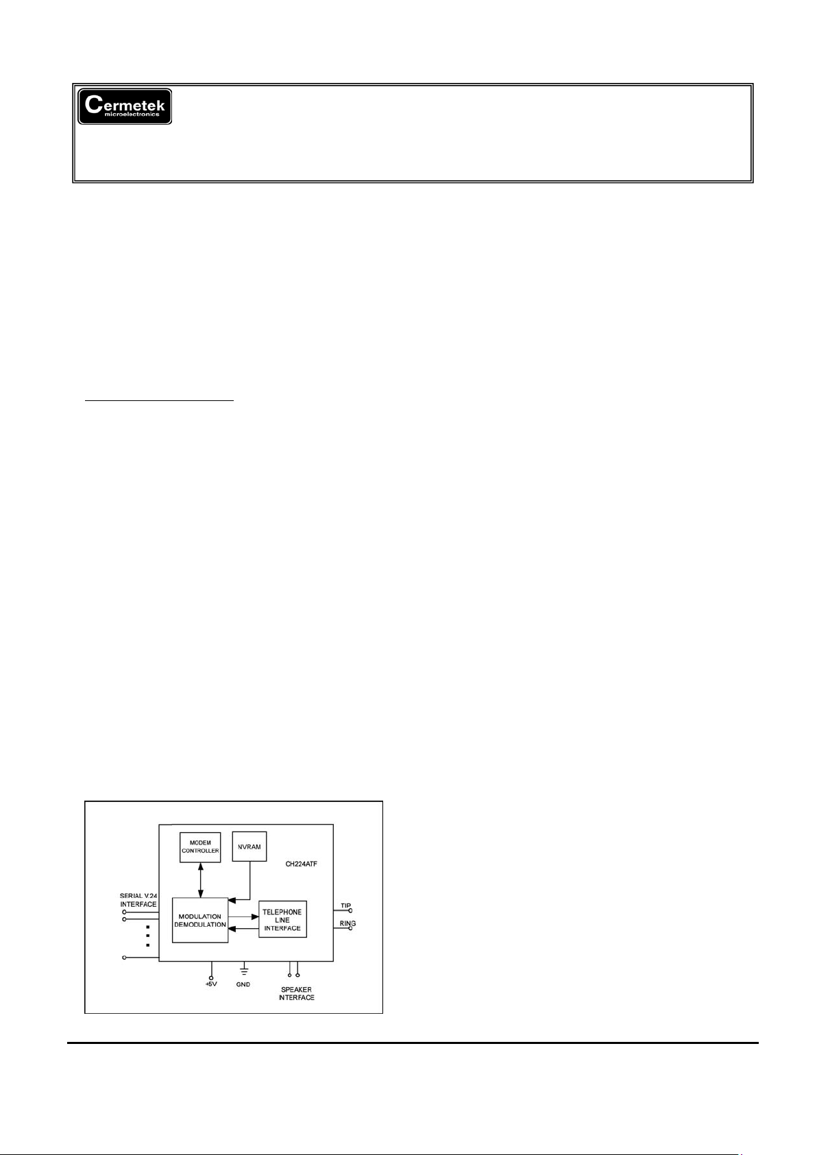
The CH224ATF requires two external interfaces: a
CCITT V.24 serial interface that is routed directly
from the UART or UART interface, and a TIP and
RING interface, which is connected directly to a
conventional RJ-11 jack for the PSTN line
connection. The CH224ATF also has various
indicator and status lines to monitor operations or
to establish triggers. The CH224ATF modem is
controlled by industry standard “AT” commands
and is compatible with available industry
communication software.
The device supports asynchronous operation at
2400 bps, 1200 bps, and 300 bps to both Bell and
CCIT standards. The resident PSTN line interface
is FCC Part 68 approved, and is also Canadian
DOC approveable, and can be approved in other
countries that require 1500VAC RMS isolation.
Figure 1. Functional Block Diagram of
CH224ATF
FEATURES
• FCC Part 68 pre-approved
• UL1950, 3rd edition listed
• 1500 Vrms isolation
• Complete solution: on-board DAA
• Data modes
- CCITT v.22 bis (2400 bps), V.22 (1200
bps)
- Bell 212A (1200 bps) and 103 (300
bps)
- Enhanced AT commands
• Group 3 fax modes
- V.29 (6900/7200 bps) transmit
- V.27 ter (4800/2400 bps) transmit and
receive
- V.21 Channel 2 (300 bps) transmit
and receive
• EIA-578 Service Class 1 commands
• V.42/MNP2-4 and V.42 bis/MNP5 support
without additional hardware
• Data/fax discriminator and auto answering
• Communications software compatible
• Serial asynchronous DTE interface
• NVRAM interface allows storage of two
user configurations and four 36-digit dial
strings
• Automatic adaptive/fixed compromise
equalization
• Programmable sleep mode
• Full-duplex data mode test capabilities:
Analog loop, local digital loop, and remote
digital loop
• Half-duplex fax mode test capabilities
• Automatic format/speed sensing
• Low power consumption (typical):
Interface Operating Sleep
Serial TTL: 155mW 35mW
• Single +5VDC power supply
TECHNICAL SPECIFICATIONS
General
The CH224ATF modem is a full-featured, selfcontained data/fax solution. External microcontroller for data or fax control functions are
fully supported and controlled through the AT
command set.
2001 Cermetek Microelectronics, Inc. Page 1 Document No. 607-0005 Revision B1 (05/02)

Cermetek Microelectronics, Inc. CH224ATF Complete 2400 bps Modem Module
Data modes perform complete handshake and
data rate negotiations. All tone and pattern
detection required by the applicable CCITT or
Bell standard are supported.
Fax modes support Group 3 fax requirements.
Fax data and fax control (V.21 300 bps)
performed by the modem is controlled and
monitored through the fax EIA-578 Class 1
insertion/deletion, and CRC
generation/checking is provided.
Both transmit and receive fax data is buffered
within the modem. Data transfer to and from
the DTE is flow controlled by XON/XOFF.
Configurations and Rates
The supported modem configurations and
signaling rates are listed in Table 1. In data
modes with serial interface selected, DTE rate
offsets of +1%, -2.5% are accommodated by
adding/deleting stop bits are required. In fax
modes, the DTE rate is 19200 bps.
Operation
Modem operation is controlled by AT
commands (Table 2), fax service class 1
commands (Table 3), and supporting S registers
(Table 4). Result codes and messages are
listed in Table 5.
Data Modes: Data rate selection is determined
by the speed of the originating and answering
modems:
Originate Modem Connect Speed Based on
Answer Rate Modem Rate (bps)
(bps)
300 1200 2400
300 300 300 300
1200 1200 1200 1200
2400 1200 1200 2400
Fax Modes: Fax modes are negotiated as
defined in T.30 and are implemented by AT+F
commands. The AT+FCLASS=1 command
causes entry into the fax mode from the data
mode. Most other fax class 1 commands,
which start with the AT+F prefix, are valid only
in the fax mode.All data commands are valid
in the fax mode except A/, On & Tn, and the
escape sequence (+++). The AT+FCLASS=0
command terminates the fax mode and
causes entry into the data mode.
AT Command Format
Each command line must start with the AT
prefix and be terminated with a carriage return
(CR). Several commands may be included on
one command line. A command line may
contain up to 40 characters excluding the AT
prefix and the terminating CR. A separator is
not required between data commands. A
semicolon (;) separator is required between
fax commands.
AT commands are composed of 10-bit ASCII
encoded asynchronous characters. The
character format in data mode is 8 data bits
with no parity, or 7 data bits with even, odd, or
no (two stop bits) parity, at a data rate of
19200, 2400, 1200, or 300 bps. The
character format in fax mode is 8 data bits
with no parity at 19200 bps.
Data Modulation
The data modulation conforms to V.29, V.27
ter, V.22 bis, V.22, V.21, Bell212A, or Bell
103, depending on the selected configuration.
Transmitter and receiver spectrum shaping is
provided in accordance with the applicable
standard.
Equalization
Automatic adaptive qualization as well as
fixed compromised equalization is provided to
compensate for line distortions and to
minimize the effects of the intersymbol
interference.
Scrambler/Descrambler
The modem incorporates a self-synchronizing
scrambler/descrambler satisfying the
applicable CCITT or Bell requirements.
2001 Cermetek Microelectronics, Inc. Page 2 Document No. 607-0005 Revision B1 (05/02)
Cermetek Microelectronics, Inc. CH224ATF Complete 2400 bps Modem Module
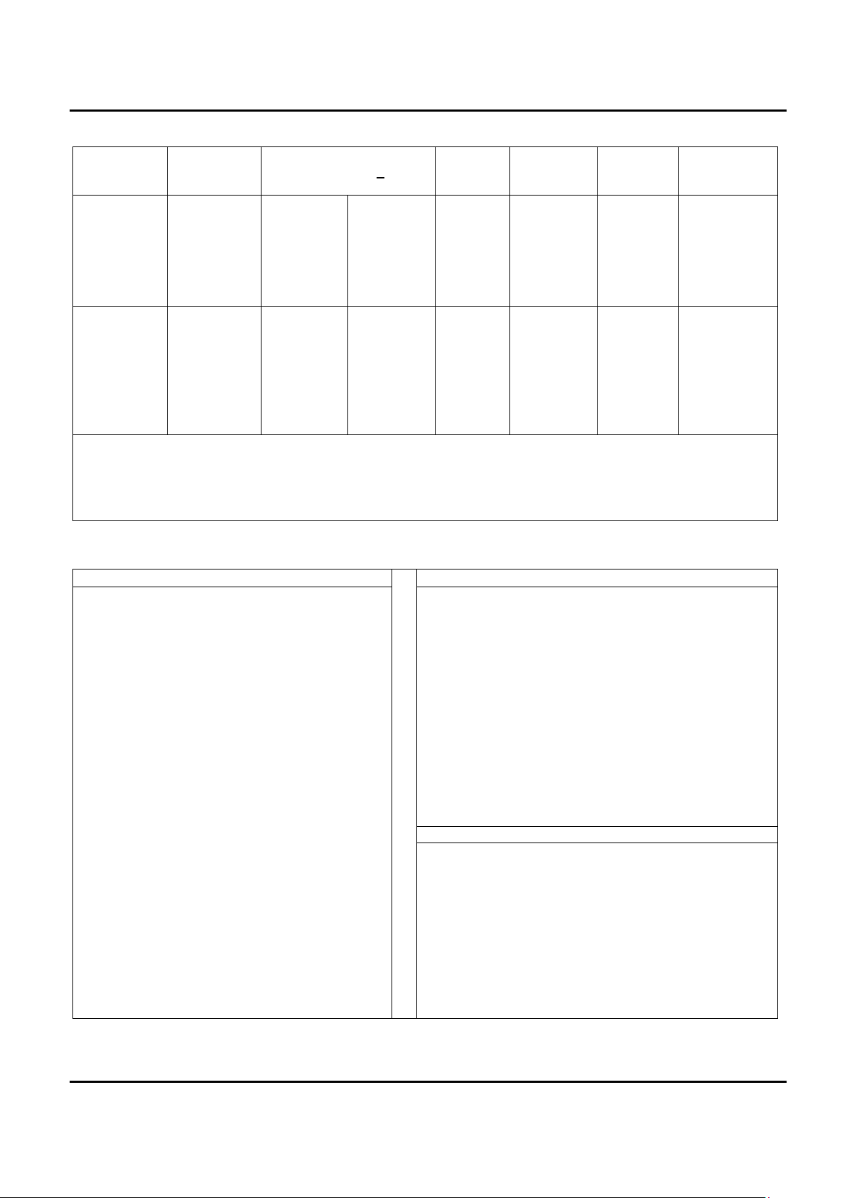
Table 1. Configurations and Rates
Configurati
on
Modulation Transmitter Carrier
Frequency (Hz) +
0.01%
Data
Rate
(bps)
Baud
(Symbols/
Sec.)
Bits Per
Symbol
Constellation
Points
Data Mode
V.22
V.22
Bell 212A
Bell 103
QAM
DPSK
DPSK
FSK
Answer
2400
2400
2400
2225
2025 S
Originate
1200
1200
1200
1270 M
1070 S
2400
1200
1200
300
600
600
600
300
4
2
2
1
16
4
4
1
Fax Mode
V.29
V.22
Bell 212A
Bell 103
QAM
DPSK
DPSK
FSK
Receive
N/A
N/A
1800
1800
1650 M
1850 S
Transmit
1700
1700
1800
1800
1650 M
1850 S
9600
7200
4800
2400
300
2400
2400
1600
1200
300
4
3
3
2
1
16
8
8
4
1
Notes:
Legend: QAM = Quadrature Amplitude Modulation M = Mark Condition
DPSK = Differential Phase Shift Keying S = Space Condition
FSK = Frequency Shift Keying N/A = Not Applicable
Table 2. “AT” Command Set Summary
Command Function Command Function
A/ Re-execute command &Jn Telephone jack control
A Answer a call &L0 Dial-up line operation
Bn Select CCITT or Bell Mode &M0 Asynchronous mode
Cn Carrier control &Pn Pulse dial make/break ratio
Dn Dial modifier &Q0 Asynchronous mode
En Command echo &Sn DSR override
F1 On-line character echo option &Tn Test and diagnostic
Hn Disconnect (Hangup) &V Display current configurations
In Identification &Wn Store current configuration
Ln Speaker volume &X0 Asynchronous data transmission
Mn Speaker control &Yn Select default profile
On Go on-line &Zn=x Store dial string to location n
P Force pulse dialing %Dn DTMF Level Attenuation
Qn Quiet Result codes control %J Load Secondary Defaults
Sn Select S register as default %Ln Transmit Level Attenuation
Sn=v Set default S register to value Dial Modifier Function
Sn? Return the value of S register P Pulse Dial
T Force DTMF dialing R Originate Call in Answer Mode
Vn Report codes form S=n Dial Stored Number
Xn Extended result codes T Tone Dial
Yn Long space disconnect W Wait for Dial Tone
Zn Soft reset and restore profile ; Return to Idle State
&Cn RLSD (DCD) option @ Wait for Quiet Answer Command
&Dn DTR option ! Flash Hook
&F Recall (restore)factory profile , Pause
&Gn Select guard tone 0-9, A, B, C, D, #, * Dial Digits/ Characters
2001 Cermetek Microelectronics, Inc. Page 3 Document No. 607-0005 Revision B1 (05/02)

Cermetek Microelectronics, Inc. CH224ATF Complete 2400 bps Modem Module
Table 3. FAX Command Set Summary Table 4. Register Summary
FAX Command Function
Register Function
+FCLASS=n Service class SO* Rings to Auto –Answer
+F<command>? Report Active Configuration S1 Ring Counter
+F<command>=? Report Operating Capabilities S2 Escape Character
+FAA=n Data/Fax Auto Answer S3 Carriage Return Character
+FF Enhanced flow Control S4 Line Feed Character
+FTS=n Stop Transmissions & Wait S5 Backspace Character
+FRS=n Receive Silence S6 Maximum time to Wait for Dial
Tone
+FTM=n Transmit Data S7 Wait for Carrier
+FRM=n Receive Data S8 Pause Time for Comma
+FTH=n Transmit Data with HDLC
Framing
S9 Carrier Detect Response Time
+FRT=n Receive Data with HDLC
Framing
S10 Carrier Loss Disconnect Time
+FRTn Receive Test Data S11 DTMF dialing Speed
+FTTn=m Transmit Test Data S12 Escape Prompt Delay
+Hn Rockwell Protocol Interface (RPI
Enable)
S14* General Bit mapped Options (&T)
S16 Fax Mode Null Byte Timer
Table 5. Results Codes & Messages
S17 Test Timer
Digit
Code
Word Code Meaning
S18* Rockwell Protocol Interface
Speed
0 OK Command line executed without
errors
S19 Fax ode Inactivity Timer
1 CONNECT Connection at 300bps S20 General bit Mapped Options
2 RING Ringing signal detected S21* General bit Mapped Options
3 NO
CARRIER
Carrier lost or never present S22* General bit Mapped Options
4 ERROR Invalid command, checksum,
error in command line, or
command line exceeds 40
characters
S23* General Bit Mapped Options
5 CONNECT
1200
Connection at 1200 bps S24 Sleep Inactivity Timer
6 NO DIAL
TONE
No dialtone detected S25* Delay to DTR Off
7 BUSY Busy signal detected S26* RTS-to-CTS Delay
8 NO
ANSWER
No silence detected when dialing
a system not providing a dialtone
S27* General Bit Mapped Options
10 CONNECT
2400
Connection at 2400 bps S28* General Bit-Mapped Options
+F4 +FCERROR Fax carrier error * Register value may be stored in one of two user
profiles with the AT&W command.
13 DATA Connected as data modem
during auto answer
15 FAX Connected as fax modem during
auto answer
Data/Fax Auto Answering
The modem can automatically determine if the incoming
call is from a data or fax modem, make the appropriate
connection, and inform the DTE of the connection type.
2001 Cermetek Microelectronics, Inc. Page 4 Document No. 607-0005 Revision B1 (05/02)
 Loading...