

CRMET CH1787ET, CH1787 Datasheet
CH1787
Small Footprint Hardware Controllable 2400bps Modem
INTRODUCTION FEATURES
The CH1787 is a small footprint, full function 2400bps,
V.22bis asynchronous modem designed to be used in
applications where there is little or no external controller
intelligence to command the modem. The CH1787
allows the user to operate the modem via hardware
resources only, not requiring AT command execution
for basic operation. For those applications where an
external controller is available, the CH1787 operates
like a standard AT Command driven modem.
• Supports Standards CCITT V.22bis, V.22, Bell 212,
and Bell 103
• FCC Part 68 approved and DOC approvable
• Does not require a microprocessor to operate
• Pin activated hang-up
• Pin activated answer
• Manual originate and answer pins
• AT Command structure available
• UL1459 Recognized
• 1000 VAC isolation barrier, 1500V peak isolation
• Single 5 volt operation The CH1787 is ideal for use as a remote modem in
applications such as alarm products and in industrial
controllers. The CH1787 will dial a pre-stored
telephone number under pin activation control to make
a connection with another modem. The CH1787 can
also answer incoming calls (either automatically or
manually) using the ANS pin. A call is terminated by
activating the HNG pin.
• Low power sleep mode
• Automatic adaptive and fixed compromise
equalization
• Test modes and diagnostics
• Size: 2.0” X 1.25” X 0.53”
• NVRAM allows storage of custom configurations
and telephone numbers
• Commercial operating temperature: 0° to 70°C
• Extended temperature: –40° to 85°C (CH1787ET)
GENERAL DESCRIPTION OF FUNCTIONAL
BLOCKS
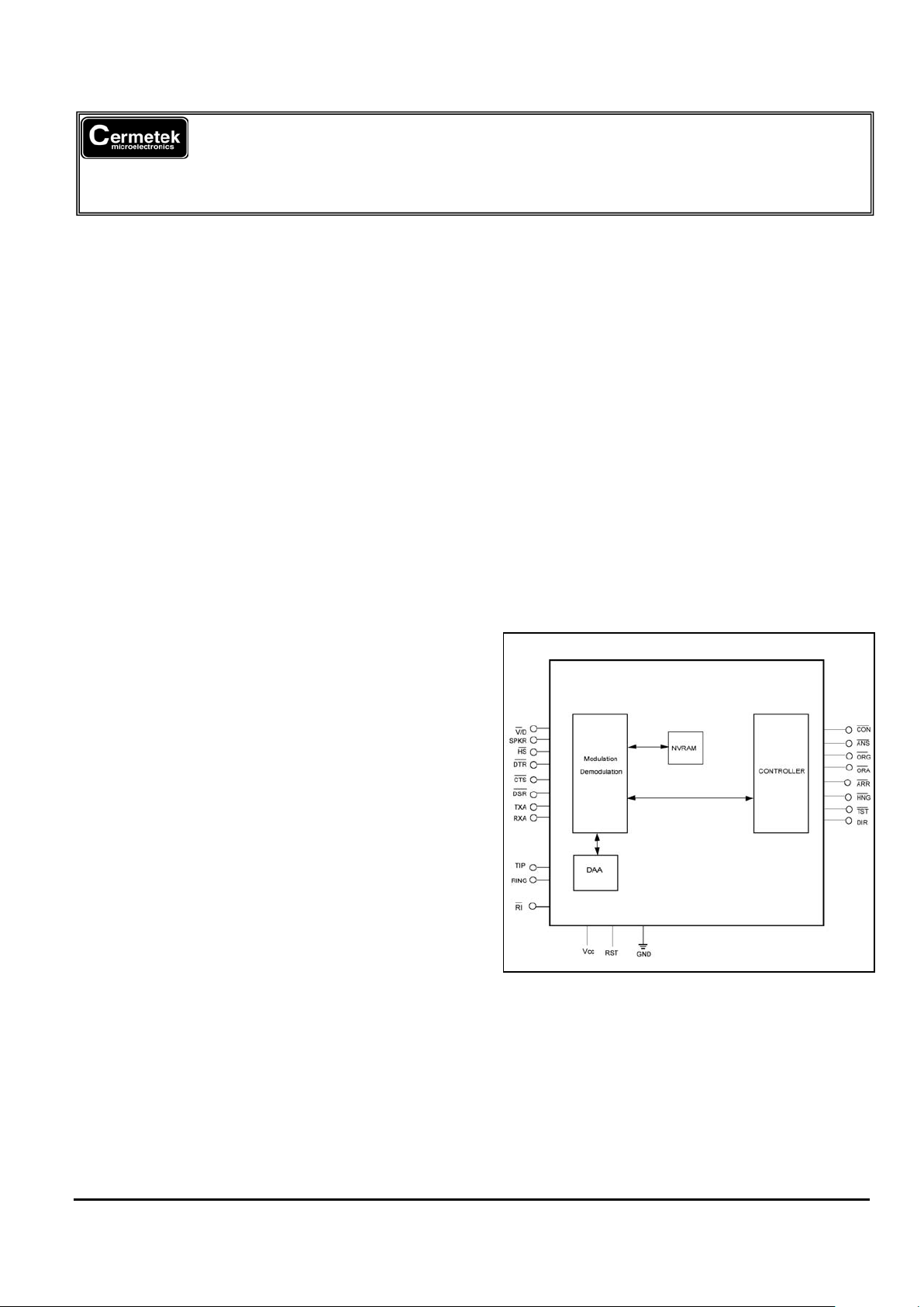
Figure 1 contains a functional block diagram of the
CH1787. The CH1787 is comprised of a
modulator/demodulator, controller, an FCC Part 68
approved telephone interface Data Access
Arrangement (DAA) and NVRAM.
Modulation/Demodulation and Control. This
functional Block is comprised of a monolithic modem
integrated circuit, with built-in facilities to accommodate
integrated AT command control and resident interfaces
for general communication and routing to the DAA.
Controller. The controller is a programmed
microprocessor that provides commands to the modem
in response to external pin activation. The following
pins are controlled by the microprocessor and are
described in detail in Table 1. These pins are
operational when the modem is in use at 2400bps only.
ANS Manual Answer Pin Input – Answer mode –
Places modem in answer mode
Figure 1. CH1787 Functional Block Diagram.
ORG Manual Originate Pin Input – Originate
mode – Places modem in originate mode
DAA. The CH1787 is designed to meet North
American telephone standards as set by FCC Part 68
and DOC. The telephone line interface meets UL1459
with 1000VAC and 1500 volt peak surge isolation. As
such, it complies with U.S., Canadian, and other
international requirements that specify that level of
isolation. The CH1787 is FCC Part 68 pre-approval. A
label is provided with the registration number and ringer
equivalent (REN). This label should be prominently
displayed on the host equipment. As with most
ORA Automatic Dial Pin Input – Dials one of two
pre-stored numbers based on TST
HNG Forces CH1787 to disconnect
AAR Enables Auto Answer
TST Selects phone number to be dialed. Works
with ORA
2002 Cermetek Microelectronics, Inc. Page 1 Document No. 607-0002 Revision B (03/02)
Cermetek Microelectronics, Inc. CH1787 Small Footprint Hardware Controllable 2400bps Modem
countries (except the U.S.), Canada requires
submission of the product containing the CH1787 for
DOC approval. This can be done by submitting the
design to a test house or consultant. Call Cermetek for
assistance.
NVRAM. NVRAM can save a maximum of four
telephone numbers with up to 36 digits or modifiers in
each. The AT&Zn=s command will store s, the
telephone number dial string. The ATDTS=n command
will cause the CH1787 to dial one of the four stored
telephone numbers. The NVRAM storage location for
the four telephone numbers is selected by an n of 0, 1,
2, or 3. Location 1 is used for the ORA stored numbers
and Cermetek number. The AT&Wn command will
store the active configuration in one of two NVRAM
locations as selected by an n of 0 or 1. The AT&Yn
command selects one of the stored configurations to be
automatically recalled and made active upon reset or
power up. The ATZn command immediately recalls
and activates a stored configuration. See Table 2 and
3 for storable S-Registers and Commands.
SUPPORTED FEATURES
AT Command Set. A 40-character command line is
supported. The command line starts with AT and may
contain standard or enhanced commands. See the
Cermetek website at
http://www.cermetek.com for
publication AT Commands and S-Registers.
Serial Host Interface. The serial interface is V.24
(EIA-232-D) compatible. See pin description in Table
1.
Speaker Interface. The SPK output reflects the
receiver analog input and provides a signal that can be
used to monitor call progress. Although the SPK signal
can drive a 300 load directly, the SPK signal is usually
input to an audio power amplifier and the amplifier
drives a speaker coil. Figure 5 shows how to drive an
8 speaker.
The speaker can be turned on and off with the ATMn
command. The speaker volume can be adjusted by the
ATLn command, where n is 0, 1, 2 or 3.
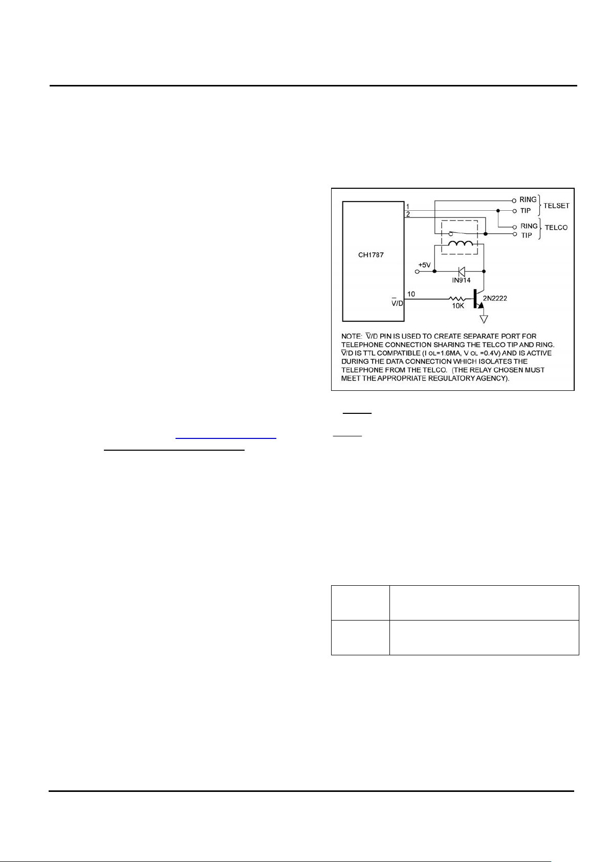
Phone Control. The Voice/Data (V/D) pin toggles high
when the modem goes off hook and can be used to
activate a relay which can switch a telephone on or off
the TIP and RING Telco lines. This feature allows the
telephone to be disconnected when a data call is in
progress, preventing the data from being disturbed by
an inadvertent telephone pick-up. See Figure 2.
SLEEP MODE
Sleep Mode is a power down feature designed to
minimize power consumption. When activated, the
CH1787 will automatically enter Sleep Mode after a
user specified period of inactivity. The inactivity
counter increments in whole seconds and is selected
by the ATS24 command. The default is 0 seconds.
The modem returns to normal operation when a ring
signal is received or upon an input low signal on TXD.
ATS24 = 255 disables Sleep Mode.
Figure 2. Voice/Data Port Control.
A SLEEP output signal is available to control power to
external devices. In Figure 5, a FET controlled by the
SLEEP signal turns off the external speaker amplifier
when the modem enters the Sleep Mode. Sleep Mode
reduces power consumption by approximately 50%.
Transmission Speed. The CH1787 can be either
originating (calling modem) or answering (remote
modem).The transmission rate of the host computer
must be 300, 1200, or 2400bps. The CH1787 will
connect at the selected speed or will fall back to the
speed set by the remote or answering modem (the DTE
transmission speed). The following table indicates the
speeds:
Originate
Speed
Connect Speed Based on Answer
Speed of:
300 1200 2400*
300 300 300 300
1200 300 1200 1200
2400 300 1200 2400
*Pin activated operation at 2400bps only. Other
speeds may be used with AT Command operation.
Speed and Parity Selection. Before a call, the
modem adjusts to the host speed (2400, 1200, or
300bps) and parity (odd, even, mark, space, or none)
via a host-initiated training sequence. This also selects
the speed of the data for originate calls. The CH1787
automatically adapts to the caller’s speed on answer
calls.
2002 Cermetek Microelectronics, Inc. Page 2 Document No. 607-0002 Revision B (03/02)

Cermetek Microelectronics, Inc. CH1787 Small Footprint Hardware Controllable 2400bps Modem
The CH1787 matches the host’s parity when it returns
status messages to the host. During a data connection,
however, the CH1787 passes parity through without
interpretation or alteration.
POWER SUPPLY
The CH1787 module is a complex sub-system that may
be treated as any other component. Special attention
should be paid to the power supply connections. The
CH1787 decodes analog signals from the telephone
line that are in the millivolt range. All though the
CH1787 is designed to withstand significantly induced
power supply noise, there is a limit. Steps must be
taken to guarantee that power supply noise on all
supply lines, including ground, does not exceed 50 mV
peak to peak. Any frequency between 20kHz and 150
kHz must be less than 50 mV peak. If necessary, use
dedicated power and ground planes. Failure to provide
such operating conditions could cause the CH1787 to
malfunction.
Figure 3. Voice/Tone Injection.
Training the Modem. The modem must be trained to
match the host’s speed and parity so that it is able to
recognize serial asynchronous commands sent to it by
the host UART. The host must retrain the modem each
time a reset signal is applied on RST or after a RESET
serial command. The modem is trained by sending it
the following three-character sequence.
The CH1787 requires a single +5V ±5% supply. It is
recommended that by-pass capacitors be placed on the
power supply as close to the modem’s supply input as
practical. It is recommended that a 10µF Electrolytic
capacitor in parallel with a 0.01µF ceramic capacitor be
used.
Enter: AT<CR>
IMPORTANT NOTE
The CH1787 has been FCC Part 68 approved as a
data modem. Utilization of the Voice/Tone Port
requires further registration. FCC will require that
the system, including the CH1787 and the handset
or DTMF transceiver, adhere to Part 68 rules.
Where: A and T must be upper case or lower
case <CR> represents carriage return
The modem will respond with one of the following
status messages, depending on whether it is optioned
for abbreviated (terse) or English (verbose) status
messages.
Response: 0<CR> terse
<CR><LF>OK<CR><LF> verbose
MODEM CONTROL
The CH1787 may be controlled by sending serial
ASCII command sequences on TXD (Pin 16). After
execution of the command, the CH1787 returns a
serial status message on RXD (Pin 31).
Where: <CR> represents carriage return (ASCII 13)
<LF> represents line feed (ASCII 13)
The CH1787 may be retrained at any time when in idle.
Initializing the Modem. Before commands may be
sent to the CH1787, the modem must be initialized.
This consists of two events: 1) after power-up, a
hardware reset pulse must be applied to the modem,
and 2) the modem must be trained to the host’s speed
(2400, 1200, 300bps) and parity (odd, even, mark,
space or none).
Another attention sequence A/ is much like the AT
sequence except it repeats the previously entered
command specified with an AT prefix. When given, it
must also be in upper case ASCII. No carriage return
is needed.
THE COMMAND FORMAT
Power-up Reset. After applying power to the modem,
an internally generated reset pulse is created. The
user can also reset the modem externally by applying a
high-going reset pulse to RST for at least 10ms after
the +5V power supply has stabilized. Delay sending
commands to CH1787 for 100-200ms after power up.
Typical commands consist of three elements: the
attention sequence, the commands themselves, and a
terminating carriage return.
2002 Cermetek Microelectronics, Inc. Page 3 Document No. 607-0002 Revision B (03/02)
Cermetek Microelectronics, Inc. CH1787 Small Footprint Hardware Controllable 2400bps Modem
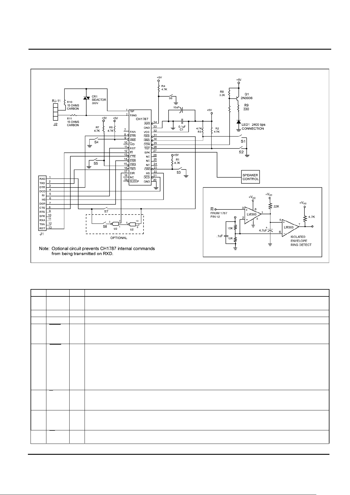
Figure 4. CH1787 Application Diagram of Test Circuit.
Table 1. CH1787 Pin Descriptions.
PIN NAME I/O FUNCTION
1 RING I/O RING. Directly connects to the telephone line’s RING lead through a user’s supplied RJ-11C
jack.
2 TIP I/O TIP. Directly connects to the telephone line’s TIP lead through a user’s supplied RJ-11C jack.
7 RXA O ANALOG VOICE INJECT. Transit and receive analog voice signal. Let float if not used.
8 DTR I DATA TERMINAL READY input. Active LOW. Switching off a DTR can either return modem
to command state, disconnect phone call, or reset modem. DTR should be set LOW when not
used.
9 ANS I ANS. Used to manually answer an incoming call. Input has two modes of operation
depending on its state during reset. When ANS is low during reset, the CH1787 will go off
hook in the answer mode and send an answer tone continuously waiting for an originating
tone. This mode of operation is used on a dedicated non dial-up telephone line (leased line).
When ANS is high during reset, the modem will initiate an answer tone whenever the ANS Pin
goes low during normal operation. The modem will send the answer tone for 30 seconds and
then stop. The CH1787 will then repeat the answer tone sequence as long as ANS is low.
10 V/D O VOICE/DATA. Used to switch between telephone and modem line use. When low, the
modem is in the control mode and a voice circuit can be switched out, RXA, TXA when high
the modem is in the data mode and the input should be TXD/TXD.
11 RST1 I RESET (active high). Must be asserted HIGH for at least 10ms to reset the modem. RESET is
then returned LOW for normal operation. If no system reset is available, let this pin float to
enable internal reset.
12 RI O RING INDICATION. This signal follows the frequency of the ringing signal which is typically 20
to 40 Hz for 2 seconds on and 4 seconds off.
2002 Cermetek Microelectronics, Inc. Page 4 Document No. 607-0002 Revision B (03/02)
Cermetek Microelectronics, Inc. CH1787 Small Footprint Hardware Controllable 2400bps Modem
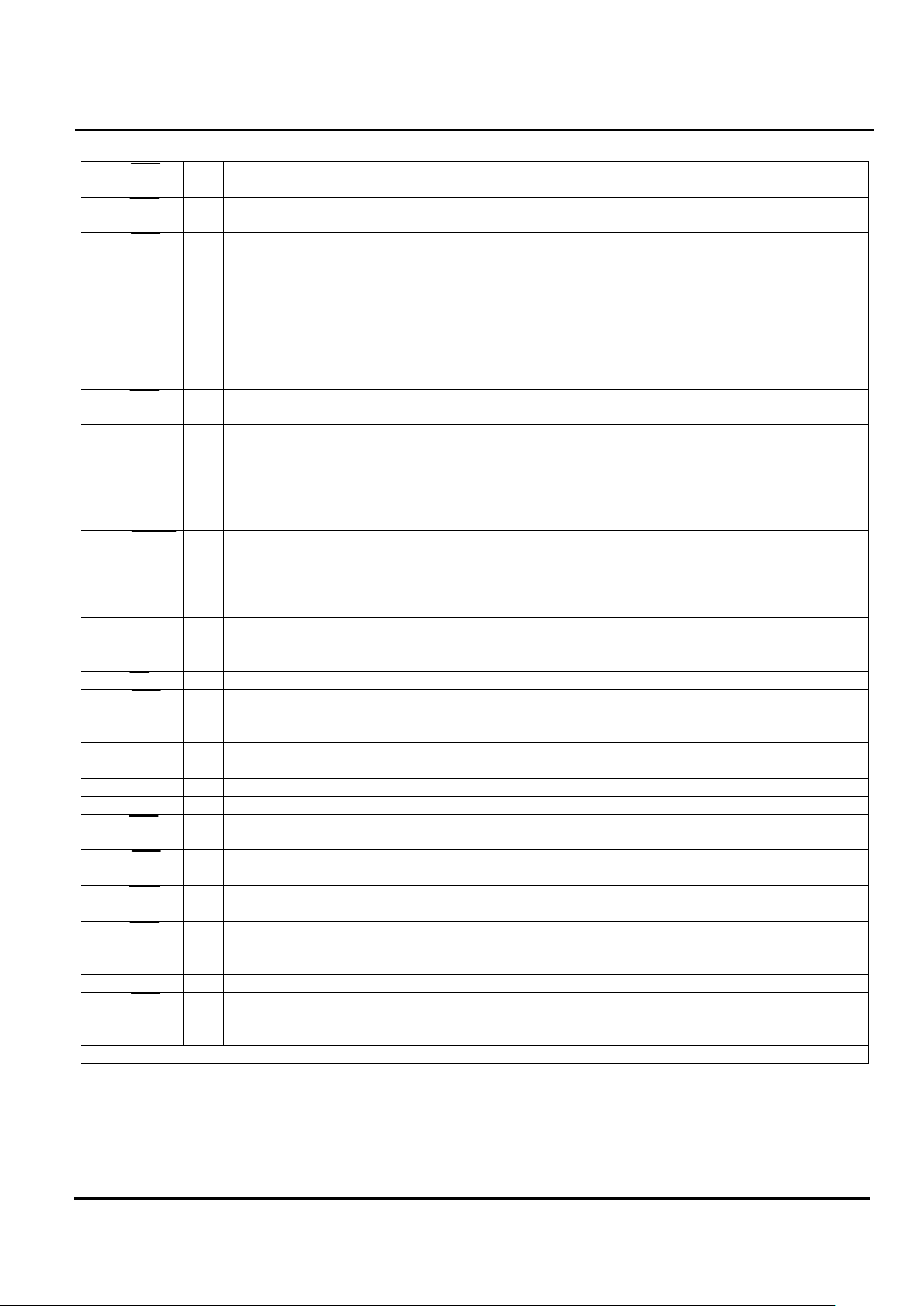
Table 1. CH1787 Pin Descriptions (Continuation).
13 CTS - CLEAR TO SEND. Active LOW. Output always low. Indicates CH1787 is ready to accept
data from DTE.
14 DSR O DATA SET READY. LOW indicates handshaking with a remote modem is in progress, and/or
the data carrier of a remote modem is detected.
15 ORA I ORA (active low). When LOW, CH1787 will dial one of two stored telephone numbers
depending on the status of the TST pin. The numbers are programmed using the AT&ZO
command. A pre-stored number is provided to allow testing. It is in permanent loop back
answering on the second ring. The CH1787 will make up 15 attempts to connect with the
stored number at 60 second intervals as long as ORA is low. DCD low indicates a successful
connection. If ORA goes high, no further attempts to connect will be made. If, after
disconnecting from a valid connection, ORA is low the CH1787 will be unresponsive until ORA
is first placed high then low. The FCC requires that automatic dialing attempts not exceed 15
to the same number.
16 TXD I TRANSMIT DATA. Serial receive data input. Marking or a binary 1 condition is transmitted
when a HIGH is asserted.
17 DIR O DIR indicates when the TXD and RXD lines are used for internal CH1787 connection. When
DIR is high, valid data is on RXD and TXD. When DIR is low, the user may ignore RXD data
and should not place any data on TXD since it will be ignored by the CH1787. The user should
monitor this pin or gate it as shown in Figure 4 to prevent data from begin erroneously
interpreted by the user’s host processor.
18 IRQ - 4.7KW resistor to 5V.
19 SLEEP O SLEEP. A LOW indicates modem is in low power idle mode. Used to control power to other
devices. See Figure 5. When the modem is inactive for a period of time specified by register
S24, the CH1787 will power down to about 50% of its normal operating power. I/O Lines will
become undefined. The factory set default for the CH1787 is sleep mode is inhibited
(S24=255).
20 GND I GROUND.
21 DCD O DATA CARRIER DETECT. LOW indicates that a data carrier from a remote modem has been
detected. DCD follows carrier is the default.
22 HS O SPEED INDICATION. A LOW on this pin indicates the modem is operating at 2400bps.
23 ORG I ORIGINATE (active LOW) places CH1787 in off hook mode without dialing. Used to originate
a connection on dedicated leased lines (i.e.,”dry” lines). The remote modem must be in
answering mode.
24 N/C - No connection.
25 N/C - No connection.
26 N/C - No connection.
27 SPK O SPEAKER. Audio Output. See Figure 5.
28 TST I Test pin input used in conjunction with ORA to steer the dialing between a user stored number
(TST LOW) and a pre-stored Cermetek test number (TST HIGH). See ORA description.
29 CON O CON indicates a valid 2400bps connection. May be used in place of DCD and HS to start the
communications or to indicate the start of an exchange of data.
30 HNG I HNG (active LOW). Used to force the CH1787 to disconnect. The HNG pin is only functional
when DCD is active (LOW).
31 RXD O RECEIVE DATA. Serial receive data output. Received MARKING or a binary 1 condition is
indicated by a HIGH.
32 VCC I 5 volts ± 5%. Note: Noise should be less than 50mV
33 GND I GROUND.
34 AAR I AAR (active LOW). When asserted low then high, CH1787 will auto answer during a RING
cycle. AAR can be tied low primarily to enable Auto Answer on the first RING. AAR will not
override auto answer condition e.g., S0 1.
Spare pins are available for custom functions. Contact Cermetek with your requirements.
Note: (1) If VCC has a slow power up ramp time, the internal reset may be ineffective.
2002 Cermetek Microelectronics, Inc. Page 5 Document No. 607-0002 Revision B (03/02)
 Loading...