

CR Magnetics CR7310 Data Sheet
3500 Scarlet Oak Blvd. St. Louis MO USA 63122 V: 636-343-8518 F: 636-343-5119
Web: http://www.crmagnetics.com E-mail: sales@crmagnetics.com
66
Relays, Switches & Sensors
D
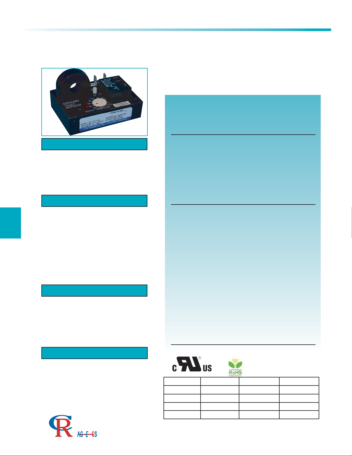
Ground Fault Sensor
CR7310 Series
The CR7310 Series, Ground Fault Sensor provides a reliable
and cost effective method for sensing ground faults. The current-carrying wires are routed through the opening extending
from the top of the case. When ground current reaches the
level set by the trip point adjustment, the relay trips, illuminates
the tripped LED and provides an output signal. A precision
voltage reference circuit ensures a highly repeatable trip point.
The Sensor is rated as a Class 1 device.
OUTPUT OPTIONS
The Relay is available with three different ouput
configurations, electromechanical relay, optoisolated NPN transistor or zero-crossing optoisolated triac. Specify desired selection in part
number.
DC SWITCHING (-NPN)
Vce (full off): 30 VDC max.
Isink (full on): 120 mADC max.@ rated full-on
Vce (full on): 1.5 VDC @ 120 mADC Isink
Off state leakage current: 5ua @ 30 VDC
(typical)
Terminals: 2
1/4”
Male Q C
RELAY (-ELR)
Arrangement: 1 Form C (SPDT)
Contact Material: Silver-cadmium oxide
Terminals: 3
1/4”
Male QC
Mechanical Life: 10 million operations,
typ.@ rated load
Electrical Life: 100,000 operations,
typ. @ rated load
Initial Contact Resistance:
50 milliohms max. @ 500 mA, 12 VDC
Contact Rating: UL508/873 & CSA
AC SWITCHING (-TRC)
Off state voltage: 240 VAC RMS max.
Minimum switch voltage: 24 VAC RMS
On state current: 500 mA RMS max. continuous
Switching mode: Zero crossing
Off state leakage: 60 ua @ 240 VAC max.
Terminals: 2 @ 1/4” Male QC
E211244
VOLTAGE LOAD TYPE
240 VAC
240 VAC
N.O. CONTACT
N.C. CONTACT
Resistive
Motor
20A
2HP
10A
1/2 HP
125 VAC
28 VDC
Motor
Resistive
1HP
20A
1/4 HP
10A
Applications
Monitor Electrical Heater Elements
Sense Motor Over/Under Loads
Detect Lamp burn-out
Indicate Phase Loss
Features
Variable Trip Point and Time Delay
Monitors Currents from 10mAAC to 100 AAC Amps
Electrical Isolation Between Circuits
Output Relay Rated up to 20 Amps
LED Trip Status Indicator
Dead Band Prevents Relay Chatter
Calibrated Dial Option Available
External Current Transformers Available
Specifications
Mounting:
3/16” dia. clearance holes on 1
15/16
” by 2
15/16
”centers
Environmental:
Operating Temperature: -30° C to +60° C
Storage Temperature: -55° C to +85° C
Power-On Delay: 100 MS MAX
Hysteresis: 5% Max.
Input Supply Power:
Typical 80mA Max 100mA
Sensed Current:
Max. Continuous: 200% Full Scale
Frequency: 60-400 Hz *
*All specifications for operation at 60 Hz only
Altitude: 2000 meters max.
(Contact factory for High Altitude applications)
Weight 0.5 LBS.
Regulatory Agencies
ISO 9001:2008 Quality Management System
The Professional
Energy Monitoring
Company
T
I
M
N
3500 Scarlet Oak Blvd. St. Louis MO USA 63122 V: 636-343-8518 F: 636-343-5119
Web: http://www.crmagnetics.com E-mail: sales@crmagnetics.com
Relays, Switches, & Sensors
D
67
Ground Fault Sensor
CR7310 Series
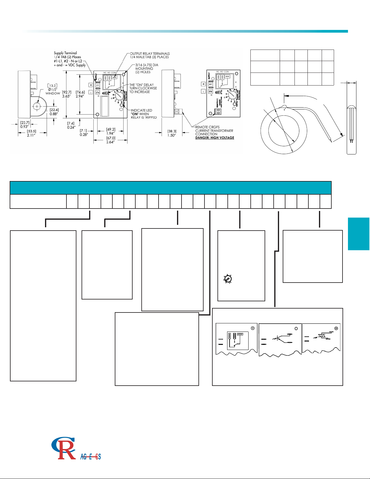
A
B
C
D
Remote Current Transformers CRGFS - Series
CRGFS
A B C D
-100
2.88
73.16
1.60
40.5812304.8
0.79
20.07
-200
3.25
82.55
1.75
44.4512304.8
0.82
20.83
TRIP RANGE
.011 - .01 to 0.1 AAC
.11 - 0.1 to 1.0 AAC
110 - 1.0 to 10 AAC
330 - 3.0 to 30 AAC
660 - 6.0 to 60 AAC
101 - 10 to 100 AAC
The trip ranges shown are for
one wire pass through the
window opening. The trip range
may be proportionally lowered
with additional wire passes
through the window.
OUTLINE DRAWING
Top view of Current Sensing Relay
Shown with Remote Current
Transformer Option (-R)
TRIP STATUS
EH - Energized on High, trips
when sense current is above trip
point and returns to non-trip
status when sense current is
below the trip point.
EL - Energized on Low, trips
when sense current is below trip
point and returns to non-trip
status when sense current is
above the trip point.
LH - Latch on High, trips when
sense current is above trip point
and remains tripped until
supply power is removed.
LL - Latch on Low, trips when
sense current is below trip point
and remains tripped until supply
power is removed.
SUPPLY VOLTAGE
AC
120 - 120 VAC
240 - 240 VAC
DC
24D - 24 VDC
All supply voltage tolerances
are ± 10 %
TRIP POINT DIAL
CD - Calibrated Dial
FP - Fixed Trip Point
(Specify value of fixed
trippoint with order)
3
5
10
15
30
20
CURRENT TRIP
25
No adjustment
dial provided with
the fixed set
point option
- CD - FP
-3.30 trip range shown
OUTPUT OPTIONS
ELR
Electromechanical
Relay
NPN
Optoisolated
NPN Transistor
TRC
Optoisolated
Triac, Zero Crossing
NC NO COM
-
+
+
TRIP ON DELAY
A - .5 to 6 Sec.
B - 2 to 25 Sec.
C - .1 to 1 Sec.
X - none
Time-on delay is the time from when the relay trips to
when the output energizes. The ranges are
guaranteed minimum, actual range may be slightly
greater.
PART NUMBER
CR7310
- - - - - - -
I - INTERNAL TRANSFORMER
R1 - REMOTE TRANSFORMER
w/ CRGFS-100
(1.60” window diameter)
R2 - REMOTE TRANSFORMER
w/ CRGFS-200
(1.75” window diameter)
Example Part Numbers:
CR7310-EH-120-.011-CD-ELR-I (Relay with CT on board)
CR7310-EL-240-.11-CD-NPN-R1 (Relay with external CRGFS-100)
The Professional
ISO 9001:2008 Quality Management System
Energy Monitoring
Company
T
I
M
N
 Loading...