

CR Magnetics CR5400 Data Sheet
CR Magnetics, Inc. 3500 Scarlet Oak Blvd. St. Louis MO USA 63122 V: 636-343-8518 F: 636-343-5119
Web: http://www.crmagnetics.com E-mail: sales@crmagnetics.com
Another HUNTINGTON ELECTRIC Company
48
Transducers
C
AC/DC Hall Effect Current Transducer
DIN RAIL / PANEL MOUNT, TRACING OUTPUT
CR5410 CR5411
Single Element - .79” Window
20 TO 300 AAC/DC Input Range
20 - ±20 AAC/ADC
30 - ±30 AAC/ADC
50 - ±50 AAC/ADC
75 - ±75 AAC/ADC
100 - ±100 AAC/ADC
150 - ±150 AAC/ADC
300 - ±300 AAC/ADC
Ranges available up to and
including 600 AAC/ADC
Add suffix for input range
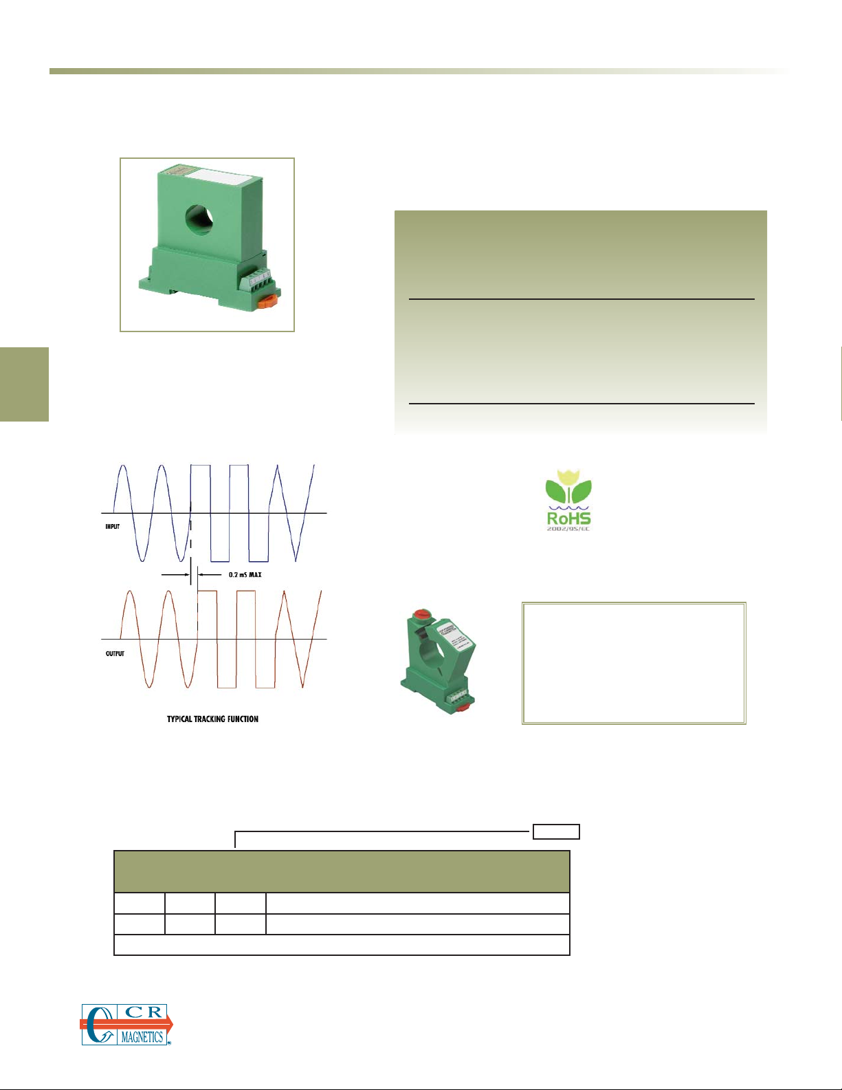
The CR5400 Series, AC/DC Hall Effect Current Transducers,
are designed to provide a bipolar output that proportionally
reflects (traces) the waveform of the input current. These
devices are specifically targeted to be used in applications
where multi-mode current sensing is required.
Applications
Inverter and multi-frequency drives
Multi-mode ground paths carrying both AC and DC signals
Feed back loop building block
Features
Output isolated from input
Non-contact current sensing
35mm DIN Rail or Panel Mount
Connection diagram printed on case
Regulatory Agencies
All single phase current transducers are
available in split core design.
Simply put an “S” at the end of the prefix
* UL Recognition Pending
PART NUMBERS
CR5410(S)
-
Single Element with
±
5 VDC output (split core design)
CR5411(S)
-
Single Element with
±
10 VDC output (split core design)
NOTE: AC/DC
Split Core Transducers Available in 20 Amps and Higher
Transducers
C
CR Magnetics, Inc. 3500 Scarlet Oak Blvd. St. Louis MO USA 63122 V: 636-343-8518 F: 636-343-5119
Web: http://www.crmagnetics.com E-mail: sales@crmagnetics.com
Another HUNTINGTON ELECTRIC Company
49
SPECIFICATIONS
AC/DC Hall Effect Current Transducer
DIN RAIL / PANEL MOUNT, TRACING OUTPUT
NOTE: The building installation must have a switch or circuit-breaker that is in close proximity and within easy reach of the operator. The switch or circuit breaker
shall be marked as the disconnecting device for the equipment.
CRPS24VDC - 120 CRPS24VDC - 240
CR5410
±5 VDC Output
CR5411
±10 VDC Output
+
-
Basic Accuracy:...................... 1.0%
Thermal Drift:.......................... 500 PPM/°C
Operating Temperature:.......... 0°C to +50°C
Insulation Voltage:................... 2500 VDC
MTBF:............................. Greater than 100 K hours
Supply Voltage:........................ 24 VDC ±10%
Frequency Range:................... DC - 4 KHz
Output:..................................... ±5VDC or ±10VDC
Output Load:............................ 2 K Ω or greater
Supply Current:
CR5410:......................Typical 35mA Max 40mA
CR5410S Typical 30mA Max 35mA
Torque Specs.:................ 3.0 inch lbs. (0.4Nm)
Weight:.............................0.5 lbs.
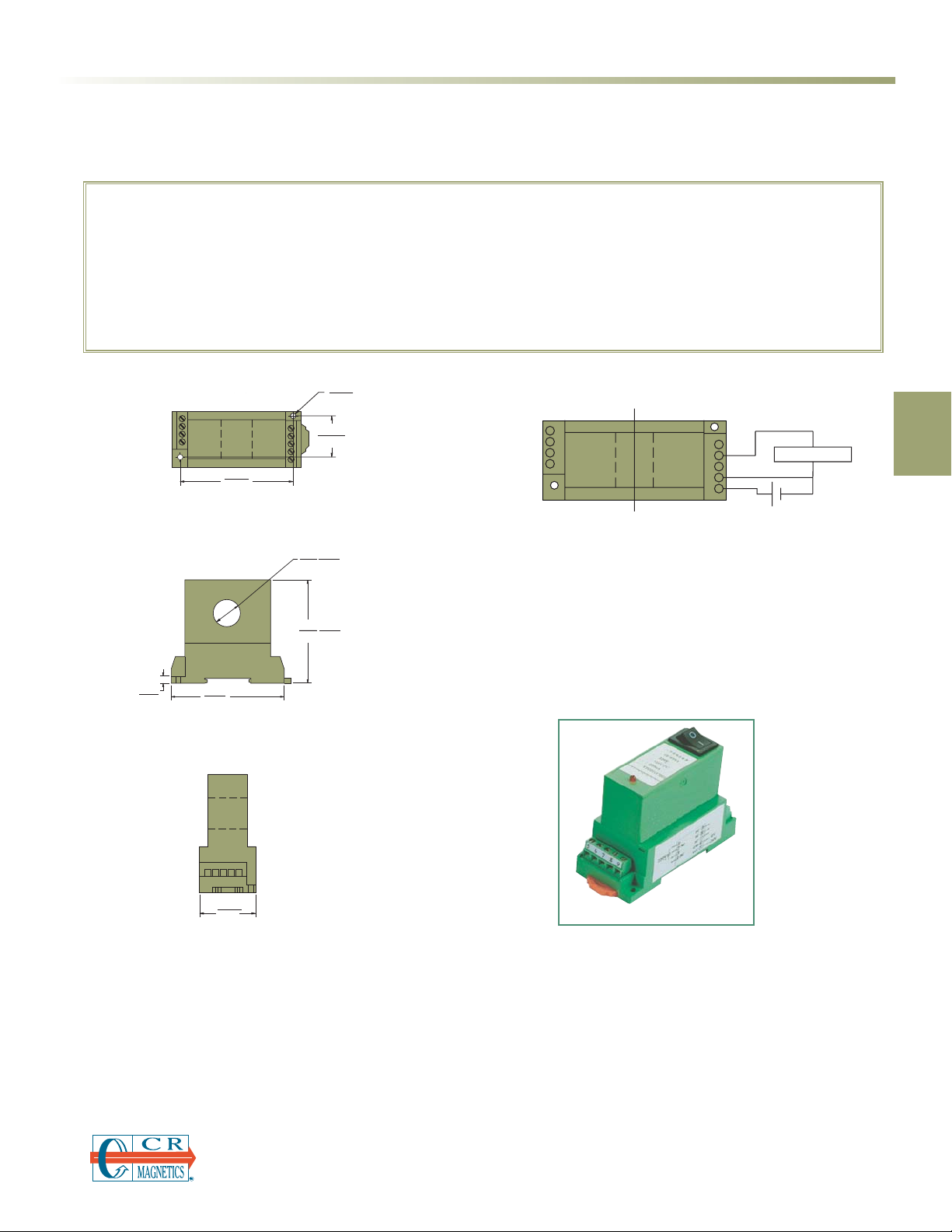
OUTLINE DRAWING
2
1 hole: 0.79(20) Dia. for CR5410 (shown)
CONNECTION DIAGRAM
Power Supply
1.42
(36) 0.14
1
2
3
4
2.874
(73)
2.874
(73)
9
8
7
6
5
0.79
(20)
2.99
(76)
1.06
(26.8)
0.79
(20)
1.22
(31)
3.86
(98)
(3.5)
1.2
(31
Split core
DIA.
Split core
1
2
3
4
9
8
7
6
5
+
OUTPUT
-
SUPPLY
+
-
0.20
(5.1)
3.268
(83)
1.42
(36)
 Loading...