

CRL JACKSON 2086 Installation Instructions Manual

INSTALLATION INSTRUCTIONS
CRL JACKSON 2086
CONCEALED VERTICAL ROD
PANIC EXIT DEVICE
crlaurence.com
Phone: (800) 421-6144 • Fax: (866) 921-0531
crlaurence.com • usalum.com • crl-arch.com
11M0263

CRL JACKSON PANIC EXIT DEVICES - 2086 CONCEALED VERTICAL ROD
ORDER OF ASSEMBLY AND INSTALLATION
PARTS IDENTIFICATION ���������������������������������������������������������������������������� 03 - 04
DOOR PREPARATION ����������������������������������������������������������������������������������� 05
LAYOUT SELECTION ������������������������������������������������������������������������������� 06 - 09
HARDWARE INSTALLATION ������������������������������������������������������������������������ 10 - 14
INSERT ROD AND CASE ����������������������������������������������������������������������������� 10
INSTALL MORTISE CYLINDER LOCK AND MOUNTING PAD (OPTIONAL) ��������������������������� 11
INSTALL EXTERIOR LOCKING LEVER TRIM (OPTIONAL) ����������������������������������������� 12
INSTALL 2086 EXIT DEVICE ������������������������������������������������������������������������� 13
OPERATIONS CHECK AND DOGGING INSTRUCTIONS ��������������������������������������������� 14
FRAME PREPARATION AND STRIKE INSTALLATION ���������������������������������������������� 15 - 16
DOOR HARDWARE ADJUSTMENTS - UPPER AND BOTTOM BOLT �������������������������������������� 17
PACKAGE PARTS AVAILABLE ��������������������������������������������������������������������������� 18
TOOLS REQUIRED
Drill Bits: 1/8", 9/32", 5/16",
7/32", 5/8", 11/16", 1-3/8"
Taps: 1/4-20, 10-32, 8-32
Tape Measure
Saw Horses
Cordless Drill
Phillips Head Screw Driver
Framing Square
Masking Tape
Center Punch
Flat Metal File
Round Metal File
Jigsaw with Metal Cutting Blade
Straight Edge
NOTE: Any modications, other than those specied in this document, could result in this product's failure
to meet UL safety ratings and void the manufacturer’s warranties.
The rapidly changing technology within the architectural aluminum products industry demands that U.S. Aluminum reserve
the right to revise, discontinue or change any product line, specication or electronic media without prior written notice.
NOTE: Dimensions in parentheses ( ) are millimeters unless otherwise noted.
crlaurence.com | usalum.com
02
CRL JACKSON PANIC EXIT DEVICES - 2086 CONCEALED VERTICAL ROD
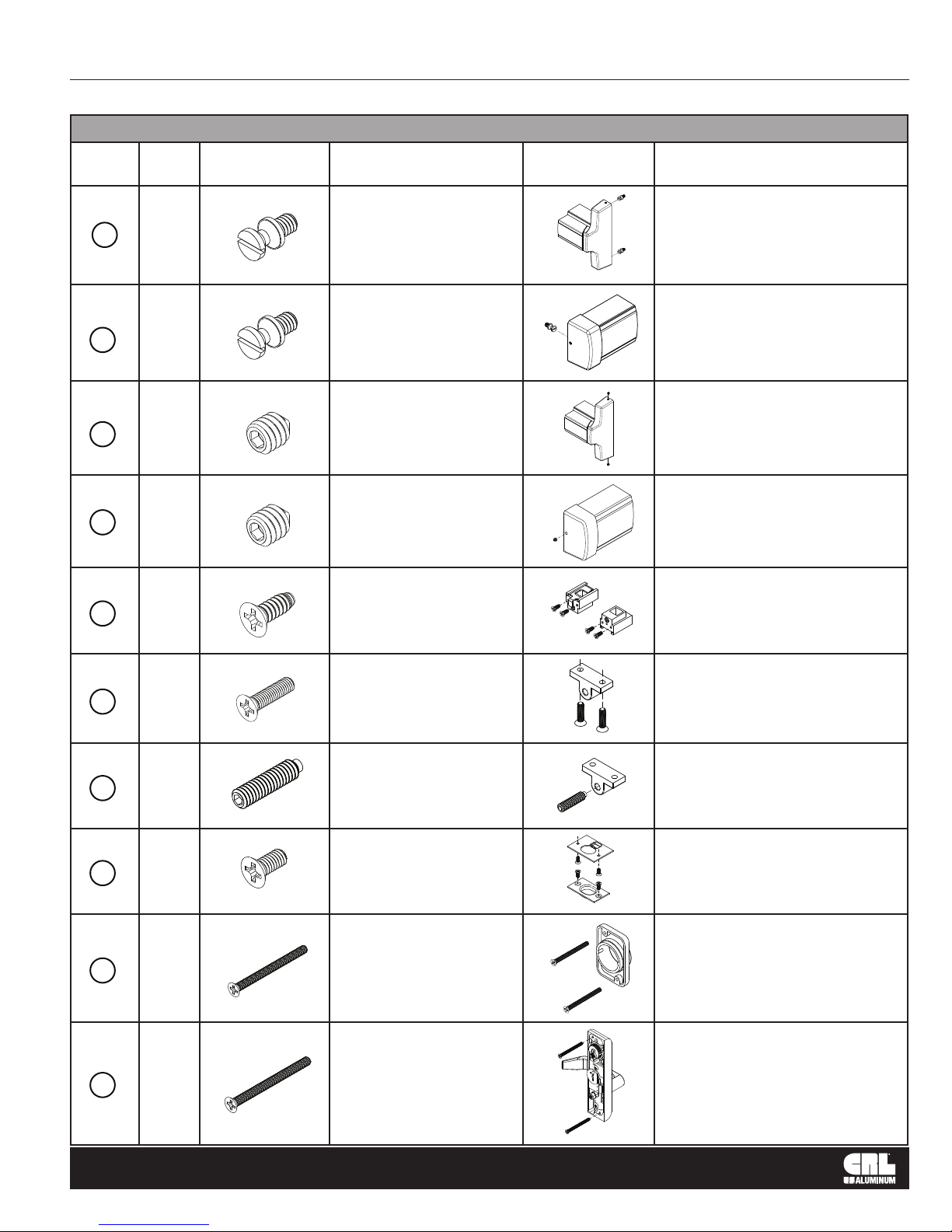
PARTS IDENTIFICATION
FASTENERS PROVIDED USED WITH
CALL
OUT
A
A
B
B
C
QTY. FASTENER
2
1
2
1
4
FASTENER
DESCRIPTION
1/4"-20 x 1/4"
Shoulder Stud
Screws
1/4"-20 x 1/4"
Shoulder Stud Screw
1/4"-20 x 5/16"
Set Screw
1/4"-20 x 5/16"
Set Screw
#10 x 1/2" FH
Self Tapping Screw
PART
PART NUMBER
AND DESCRIPTION
302617 and 302619
Active Head Assembly
301266 Base End
Cap Package
302617 and 302619
Active Head Assembly
301266
Base End
Cap Package
30934 Top Bolt Guide
30320 Bottom Bolt Guide
Assembly
D
E
F
G
H
2
1
4
2
2
#10-32 x 3/4" FH
Machine Screw
1/4"-20 x 1"
Adjustment SScrew
#10-32 x 3/8" FH
Machine Screw
#8-32 x 2" FH
Machine Screw
#10-32 x 2-1/8"
FHMS
30824
Trip Bracket Package
30824
Trip Bracket Package
301084 Top and Bottom
Strike Package
30821J
Optional Mortise Cylinder
Mounting Pad
8500LV01 and 8500LV02
Optional Exterior Trim
with Lever Assembly
crlaurence.com | usalum.com
03
CRL JACKSON PANIC EXIT DEVICES - 2086 CONCEALED VERTICAL ROD
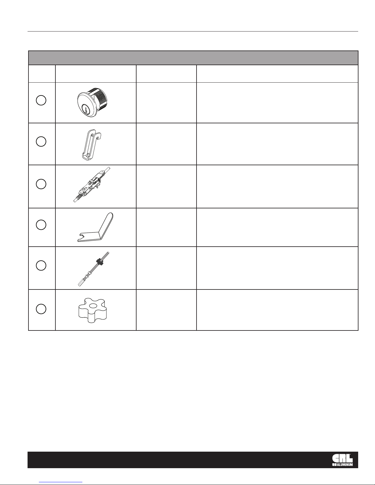
PARTS IDENTIFICATION
PARTS LIST
CALL
OUT
I
J
K
L
PART PART NO. DESCRIPTION
DL2170
Optional 1" Single
Mortise Cylinder
Actuator Link included in 2086
30799
Active Head Assembly
Hardware Package 302607
30915J Rod and Case Assembly - 7/0
30PBAW
Bolt Guide
Adjustment Wrench
M
N
301347
301348
Optional 12" and 24"
Top Rod Extender
301552PKG Rod Silencers (12 Pkg.)
crlaurence.com | usalum.com
04
CRL JACKSON PANIC EXIT DEVICES - 2086 CONCEALED VERTICAL ROD
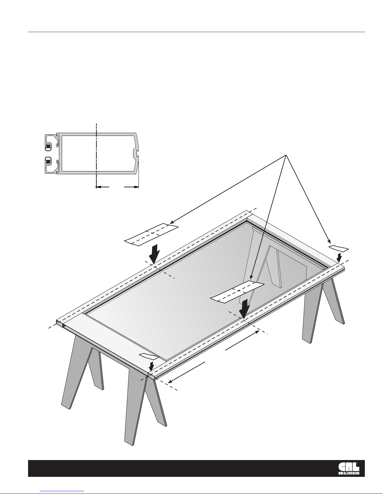
DOOR PREPARATION
REMOVE DOOR AND PREPARE PER TEMPLATE
1. Place the door horizontally on the stands interior side up.
2. Mark the stile centerlines 1-1/8" (28.6) from the inside edge. (Fig. 1)
3. Mark the corresponding layouts on to the stile using the vertical centerlines at the specied height. (Fig. 2)
TEMPLATES
1-1/8"
(28�6)
Y
FIG. 1
Y
Y
Y
BOTTOM RAIL
Y
X
X
TOP RAIL
HINGE STILE
Y
X
Y
ACTIVE STILE
X
SEE TEMPLATE FOR
HEIGHT DIMENSIONS
INTERIOR VIEW
crlaurence.com | usalum.com
FIG. 2
NOT TO SCALE
05
CRL JACKSON PANIC EXIT DEVICES - 2086 CONCEALED VERTICAL ROD
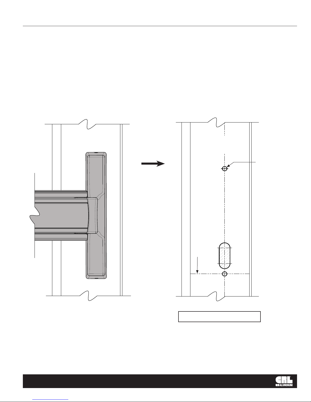
DOOR PREPARATION – LAYOUT SELECTION
2086 EXIT DEVICE INSTALLATION - ACTIVE STILE
Glass Stop
INTERIOR VIEW
ACTIVE STILE
Edge of Door
2086 Active Side
Mounting Inside Face
Glass Stop
35" (889) to Bottom
of Door From This Line
10-952
Drill and Tap
for a 1/4"-20
Machine Screw
(2)-Places
Edge of Door
crlaurence.com | usalum.com
Use Template from Box
FIG. 3
NOT TO SCALE
06
 Loading...