

Critikon Dinamap Compact User manual
DINAMAP Compact
Monitor
Operation Manual
1
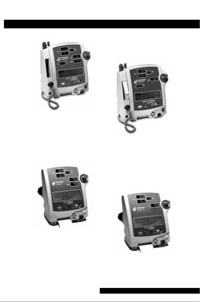
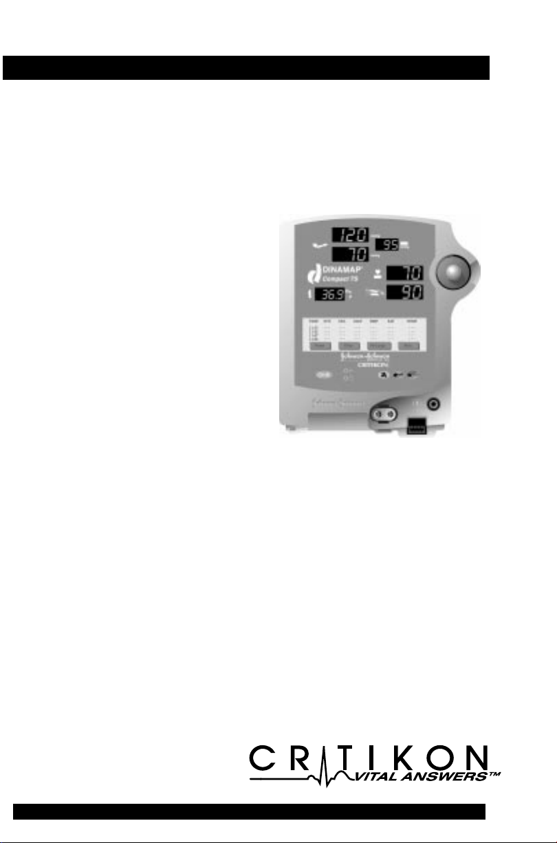
DINAMAP® Compact
Monitor Model TS
DINAMAP® Compact
Monitor Model S
DINAMAP® Compact
Monitor Model T
DINAMAP® Compact
Monitor Model BP
2

DINAMAP Compact Monitor
Operation Manual
This manual is for DINAMAP Compact Monitor
Models T, S, TS, and BP, with and without printers.
• Model T: BP, Pulse, and Temp
• Model S: BP, Pulse, and SpO
• Model TS: BP, Pulse, Temp, and SpO
• Model BP: BP and Pulse
The model of the Monitor determines which menu option
buttons appear on the LCD. Please refer to applicable
sections.
2
2
Reissues and Updates
Changes occurring between issues are addressed through
Change Information Sheets, Addendums, and replacement
pages. If a Change Information Sheet does not accompany
this manual, it is correct as printed.
Errors and Omissions
If errors or omissions are found in this manual, please
notify:
Critikon
4110 George Road
Tampa, FL 33634
1-800-237-2033
Part No. 776980A (USA; Printed in USA)
Part No. 8796EM05 (UK; Printed in UK)
The content of this document including all figures and
drawings is proprietary information of Critikon, provided
solely for purposes of operation, maintenance or repair, and
dissemination for other purposes or copying thereof is
prohibited without prior written consent by Critikon, Tampa,
Florida.
Illustrations may show design models; production units may
incorporate changes.
© CRITIKON 1998, TAMPA, FL 33634
All rights reserved.
3

United States
Critikon, L.L.C.
4110 George Road
Tampa, FL 33634
Canada
Johnson and Johnson Medical Products
1421 Lansdowne Street West
Peterborough, Ontario, Canada K9J 7B9
United Kingdom
Critikon LTD
Coronation Road
Ascot
Berkshire SL5 9EY
UK
Australia
Johnson and Johnson Medical Pty. LTD
1-5 Khartoum Road
North Ryde, NSW 2113
Australia
4

Contents
Introduction ..........................................................................7
About the DINAMAP® Compact Monitor .......................................................... 7
Indications .................................................................................................................. 7
Contraindications......................................................................................................7
Warnings.....................................................................................................................7
Cautions...................................................................................................................... 8
Product Compliance ..............................................................................................10
Symbols.....................................................................................................................11
Getting Started ....................................................................13
Unpacking the Monitor and Accessories ..........................................................13
Power Sources........................................................................................................ 13
Powering the Monitor............................................................................................13
Rear Panel Connections........................................................................................16
Front Panel Controls and Indicators ...................................................................17
Installing the Temp Probe Holder .......................................................................19
Switching the Monitor On and Off ....................................................................19
Liquid Crystal Display (LCD) ............................................................................... 20
Using the Printer .................................................................................................... 21
Cautions....................................................................................................................22
Using the Monitor...............................................................23
Noninvasive Blood Pressure Determination .....................................................23
General Warnings...................................................................................................24
General Cautions....................................................................................................25
Predictive Temperature Determination ............................................................. 31
General Warning.................................................................................................... 31
General Cautions....................................................................................................31
SpO2 .........................................................................................................................32
General Warnings...................................................................................................33
General Cautions....................................................................................................34
General Notes ........................................................................................................ 34
Warnings...................................................................................................................35
Cautions....................................................................................................................35
Introduction .............................................................................................................41
Using the Menu System......................................................41
SelectKnob ...............................................................................................................44
Menu Tree................................................................................................................44
Main Menu ..............................................................................................................44
Vitals Button (UK: All Obs).................................................................................. 45
Clear ..........................................................................................................................45
Print...........................................................................................................................45
More... Button......................................................................................................... 45
Set BP Button (UK: BP Mode) .............................................................................46
Alarms Button......................................................................................................... 47
Temp Button (Models T and TS)..........................................................................48
Print Button ..............................................................................................................49
Auto/Man .................................................................................................................49
Now .......................................................................................................................... 49
History.......................................................................................................................50
More... Menu...........................................................................................................50
SpO2 Button (Models S and TS) .........................................................................50
Config Button ......................................................................................................... 51
Pwr Sav (Sleep Mode) ...........................................................................................52
Time .......................................................................................................................... 52
5

Rotor (SelectKnob) .................................................................................................53
Trend Button ............................................................................................................53
Display ......................................................................................................................53
Newer and Older....................................................................................................54
Print page .................................................................................................................54
Clear ..........................................................................................................................54
Print All......................................................................................................................54
Display Button ........................................................................................................ 54
Service Button ........................................................................................................ 55
Clinician Menu ....................................................................................................... 56
Alarms Button......................................................................................................... 60
OK Button ................................................................................................................60
Error and Warning Messages ...............................................................................60
Appendix A ..........................................................................61
Technical Specifications ........................................................................................61
Environmental......................................................................................................... 65
Appendix B ..........................................................................67
Patient Alarms......................................................................................................... 67
System Alarms ........................................................................................................ 67
Failsafe Alarm...........................................................................................................67
Hierarchy of Alarms ...............................................................................................68
Appendix C ..........................................................................73
Principles of Noninvasive Blood Pressure Determination..............................73
Systolic Search........................................................................................................ 74
Appendix D..........................................................................77
Compatibility Table and Reorder Codes .......................................................... 77
Appendix E........................................................................... 79
Warranty, Service, and Spare Parts.....................................................................79
Warranty ...................................................................................................................79
Extended Warranties ..............................................................................................79
Assistance and Parts...............................................................................................79
Repairs.......................................................................................................................80
Packing Instructions ...............................................................................................80
Service Manuals ..................................................................................................... 80
Appendix F...........................................................................81
Maintenance............................................................................................................81
Storage and Battery Care......................................................................................83
Fuses ..........................................................................................................................84
Replacement of DC Line Input Power Fuse ......................................................84
Calibration................................................................................................................85
Leak Testing..............................................................................................................85
Disposal of Product Waste .................................................................................. 85
Appendix G.......................................................................... 87
Connection Details.................................................................................................87
6

Introduction
About the DINAMAP Compact Monitor
DINAMAP Compact Monitors provide noninvasive
determination of systolic blood pressure, diastolic blood
pressure, mean arterial pressure, pulse rate, temperature,
and oxygen saturation. These portable AC- and DCoperated monitors are primarily intended for use in hospital
acute care settings such as outpatient surgery, accident and
emergency, labor and delivery, GI/endoscopy, and medical/
surgical units.
The DINAMAP Compact Monitor comes in four different
models: Models T, S, TS, and BP, with and without printers.
• Model T: BP, Pulse, and Temp
• Model S: BP, Pulse, and SpO
• Model TS: BP, Pulse, Temp, and SpO
• Model BP: BP and Pulse
All of the main operations of the DINAMAP Compact
Monitor are easy to use and, in most cases, the factory
default settings will be suitable. The “Using the Monitor”
section of this manual explains how to use the system in its
most simple form, while the “Using the Menu System”
section explains how to customize measurements by using
the menu system.
2
2
Indications
The DINAMAP Compact Monitor is intended to monitor
one patient at the bedside.
Contraindications
This device is not designed, sold, or intended for use except
as indicated.
Federal law (U.S.A.) restricts this device to sale by or on the
order of a clinician.
Warnings
• Do not use the Compact Monitor in the presence of
magnetic resonance imaging (MRI) devices. There
have been reports of sensors causing patient burns
when operating in an MRI environment.
7

• Do not use the Monitor in the presence of flammable
anesthetics.
• To help prevent unintended current return paths with
the use of high frequency (HF) surgical equipment,
ensure that the HF surgical neutral electrode is
properly connected.
• To avoid personal injury, do not perform any servicing
unless qualified to do so.
• WARNING: These Monitors should not be used on
patients who are connected to cardiopulmonary
bypass machines.
• Do not use power adapters or converters other than
the AC-DC power converter supplied with the
DINAMAP Compact Monitor. Replacement power
converters are available from Critikon.
• For continued protection against fire hazard, replace
only with the same type and rating of fuse.
Disconnect the power supply before servicing.
• To reduce the risk of electric shock, do not remove the
cover or the back. Refer servicing to a qualified
service person.
• If the accuracy of any determination reading is
questionable, first check the patient’s vital signs by
alternate means and then check the Compact Monitor
for proper functioning.
Cautions
• Do not use replacement batteries other than the type
supplied with the Monitor. Replacement batteries are
available from Critikon. See Appendix D.
• The DINAMAP Compact Monitor is designed to
conform to Electromagnetic Compatibility (EMC)
standard IEC 601-1-2, 1993 and will operate
accurately in conjunction with other medical
equipment which also meets this requirement. To
avoid interference problems affecting the Monitor, do
not use the Monitor in the presence of equipment
which does not conform to these specifications.
8

Introduction
• Place the Compact Monitor on a rigid, secure surface.
Monitor must only be used with mounting hardware,
poles, and stands recommended by Critikon. See
Appendix D.
• The weight of the accessory basket contents should
not exceed 6.6 lb (3 kg).
• Arrange the power cord, air hoses, and all cables
carefully so they do not constitute a hazard.
• Verify calibration of BP and TEMP (Models T and TS)
parameters (pulse oximeter does not require
calibration). Ensure that the Compact Monitor is
functioning properly before operating the Compact
Monitor.
• Do not immerse the Monitor in water. If the Monitor
is splashed with water or becomes wet, wipe it
immediately with a dry cloth.
• Do not gas sterilize or autoclave.
Notes
• Waveforms may be distorted and readings inaccurate
when electrosurgical cautery equipment is used while
monitoring with the Compact Monitor.
• The electromagnetic compatibility profile of the
Compact Monitor may change if accessories other than
those specified for use with the Compact Monitor are
used.
• Trend data are retained in the Compact Monitor when it
is turned off, except when the default is overridden by
selecting the Trend button under the Service menu.
9

Product Compliance
The DINAMAP Compact Monitor is classified in the
following categories for compliance with IEC 601-1:
• Class l, internally powered
• Transportable
• For continuous operation
• Not suitable for use in the presence of flammable
anesthetics
• Not for use in the presence of an oxygen-enriched
atmosphere (oxygen tent)
• Type BF applied parts
NRLT/C
DINAMAP COMPACT MONITOR
CLASSIFIED WITH RESPECT TO ELECTRIC SHOCK, FIRE
AND MECHANICAL AND OTHER SPECIFIED HAZARDS
ONLY IN ACCORDANCE WITH CAN/CSA C22.2 NO.
601.1. ALSO EVALUATED TO IEC-601-2-30.
0086
This product conforms with the essential requirements
of the Medical Device Directive. Accessories without
the CE mark are not guaranteed to meet the Essential
Requirements of the Medical Device Directive.
10
Introduction
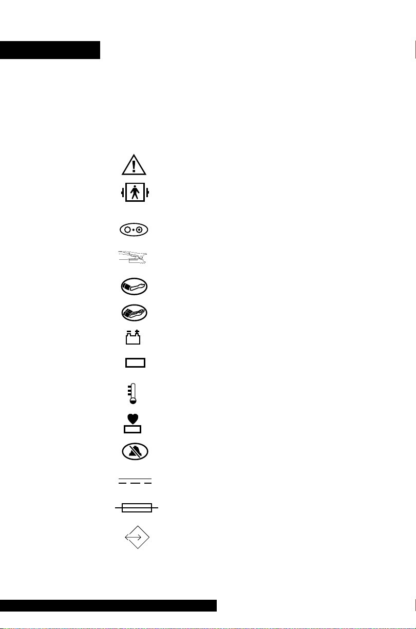
Symbols
The following symbols are associated with the Compact
Monitor.
Note: The type of model determines which symbols appear
on the Monitor.
Attention, consult accompanying
documents
Defibrillator-proof type BF equipment
Power (ON/OFF)
SpO
2
BP (START/STOP)
BP STAT
Battery Power
MAP
mmHg
BPM
MAP (Mean Arterial Pressure)
Predictive Temperature
Beats Per Minute
Silence
External DC Power
Fuse
External Communications Port Connector
11

IPX1
Packaging label depicting the
transportation and storage
atmospheric pressure range of
500 to 1060 hPa.
The DINAMAP Compact Monitor is
protected against vertically falling drops of
water and conforms with the IEC 529
standard at level of IPX1. No harmful
effects will come of vertically falling drops
of water making contact with the Monitor.
12

Getting Started
Unpacking the Monitor and Accessories
Before attempting to use the DINAMAP Compact Monitor,
take a few minutes to become acquainted with the Monitor
and its accessories. Unpack the items carefully, and check
them against the contents checklist enclosed in one of the
accessory boxes. This is also a good time to check for any
damage or shortage. If there is a problem or shortage,
contact Critikon.
It is recommended that all the packaging be retained, in
case the Monitor must be returned for service in the future.
Power Sources
The DINAMAP Compact Monitor is designed to operate
from either an internal lead-acid rechargeable battery or an
external AC source via the AC-DC power converter supplied
with the Monitor. For replacement power converters or
rechargeable batteries, please refer to Appendix D.
For continued safety, use only the double-insulated AC-DC
power converter supplied with the Monitor.
The external DC line power input is protected by an internal
3.15 Amp fuse, type T3.15A, which can be accessed from
the rear panel. The internal battery power source is
protected by a resettable thermal fuse.
Powering the Monitor
Before the DINAMAP Compact Monitor is used for the first
time, the battery should be charged in the Monitor for at
least 24 hours.
Refer to the illustration of the rear panel connections.
Looking at the rear of the DINAMAP Compact Monitor ,
remove the battery compartment cover (2). Insert the
rechargeable battery pack into the compartment so that the
battery terminals fit into the power clips at the bottom of
the compartment. Then replace the cover. Insert the plug
from the AC-DC power converter into the external power
socket (3) and plug the converter into an AC outlet.
Refer to the illustration of the front panel controls and
indicators. With external power connected, the green
external power indicator LED (7) will light to indicate that
13

external power is being applied and that the battery is
charging. If the battery is not inserted, the external power
indicator LED will flash. When the Monitor is running on
battery power, a battery icon appears in LCD area 3 (toggling
with the time indicator) indicating the charge status.
During battery-only operation, the yellow battery power
indicator LED (8) will light. When the battery becomes
discharged and only 10% of the full charge remains, the
indicator will begin to flash and the Monitor will sound
periodic warning beeps. At this point, the Monitor should be
connected to an AC outlet to recharge the battery. If the
Monitor continues to be used without charging the battery,
the message WARNING: THE BATTERY IS TOO LOW FOR
MONITOR TO FUNCTION. TURN MONITOR OFF appears,
and the Monitor will enter the fail-safe mode. The fail-safe
mode shuts down all functions until the Monitor is turned off
and the battery is recharged or replaced.
Battery charging will take place as long as the Monitor remains
connected to an external AC power source via the supplied
AC-DC power converter. A battery that is fully discharged can
be fully recharged in 1 hour 50 minutes when the Monitor is
switched off or 8 hours if the Monitor is switched on.
Notes
• To prolong the life of the battery, keep the Monitor
connected to an AC outlet whenever possible. NEVER
allow the battery to become completely discharged. A
fully charged battery will power the Monitor for
approximately 3 to 4 hours (Model TS and T with printer:
3 hours. Model BP and T with printer: 4 hours.) and
should survive between 200 and 500 charge/discharge
cycles. When it is necessary to replace the battery, refer to
the Compatibility Table and Reorder Codes listed in
Appendix D. To ensure full charge cycles, replace only
with a recommended battery. If the Monitor is to be
stored for some time, first charge the battery and then
remove it and store it separately from the Monitor.
• For continued safety, use only a power cord of listed type
SJT, three-conductor, min. No. 18 AWG, terminated in a
hospital grade attachment plug, provided with the
14

Getting Started
following cord tag: “Hospital Grade Plug." Grounding
integrity can only be maintained when equipment is
connected to an equivalent receptacle marked
"Hospital Grade."
• Where the integrity of the external earth conductor in
the installation or its arrangement is in doubt, the
Monitor must be operated from its internal battery.
15

2
5
4
3
Rear Panel Connections
1 Pole clamp: Used to clamp Monitor to pole or stand
2 Battery compartment cover: Retains and protects
internal battery
3 External power socket: To be used with supplied AC-DC
power converter ONLY
4 Fuse holder: Holds external power source line fuse
5 Data interface connector (15-way D-type socket): Host
communications port (RS-232E serial port); Remote
alarm control. This port nonisolated for use with
equipment conforming to IEC-601 only
1
16

Getting Started
14
15
19
20
21
10
7
6
8
26
mmHg
mmHg
O
c
F
MAP
mmHg
BPM
%
2425
Front Panel Controls and Indicators
6 Power on/off switch: Controls on/off state of Monitor;
push for power on and push again for power off
7 External power indicator: Green LED indicates external
power status and battery charging status of Monitor
8 Battery power indicator: Yellow LED indicates operation
and charge status of internal battery
9 SelectKnob: Used to highlight and select items in LCD
menus; if Monitor is off, pressing SelectKnob will switch
Monitor on
10 LCD (liquid crystal display): Displays all alarms, user
interface messages, and configuration options
11 Alarm silence switch: Alternately mutes and enables
audible alarms; when pushed once after alarm sounds
(silence on), switch lights to indicate that audible alarms
have been silenced for 2 minutes
12 BP key: Press to start or stop a BP determination or
cancel BP Stat mode
16
18
9
17
13
12
11
22
23
17

13 Stat key: Press to start or stop BP Stat mode
14 Systolic pressure display: 3-digit red LED indicates
measured systolic BP in mmHg
15 Diastolic pressure display: 3-digit red LED indicates
measured diastolic BP in mmHg
16 Mean arterial pressure display: 3-digit red LED indicates
measured MAP in mmHg and shows instantaneous cuff
pressure during BP determination
17 SpO
display: 3-digit red LED indicates oxygen saturation
2
in % (Models S and TS)
18 Pulse BPM display: 3-digit yellow LED shows pulse rate
in beats per minute
19 SpO2 pulse indicator: Yellow LED in heart symbol flashes
to indicate that real-time pulse rate measurements are
being derived from SpO2 signals (Models S and TS)
20 Temperature display: 4-digit red LED indicates measured
temperature (Models T and TS)
21 °C °F display: Indicates whether temperature is being
displayed in degrees Celsius or Fahrenheit (Models T and
TS)
22 Temperature probe connector: Predictive temperature
probe cable attaches here (Models T and TS)
23 SpO2 sensor connector: SpO2 sensor extension cable
attaches here (Models S and TS)
24 Cuff connector: BP cuff hose attaches here
25 Light sensor: Automatically measures ambient light to set
LED display intensity
26 Printer door: Provides access to paper
18

Getting Started
Installing the Temp Probe Holder
Attach the temperature probe holder to the side of the
DINAMAP Compact Monitor (Models T and TS) by aligning
the back and bottom edges of the holder and the Monitor
and pressing the holder firmly to the Monitor.
A distinct snap will sound when the Dual LockTM fasteners
are properly engaged.
To remove the holder, place your fingers in the indentations
at the back of the Monitor and pull the holder away from
the side of the Monitor.
Switching the Monitor On and Off
To switch the DINAMAP Compact Monitor on, push the
power on/off switch (6) or click the SelectKnob (9).
As the Monitor powers up, it will run a short self-test
routine, which will flash all the indicator lights and then
beep the warning speaker. After a few seconds the system
will be ready for operation, as indicated by the appearance
of the main menu on the LCD (10).
To switch the Monitor off, push the power on/off switch (6)
again. This will terminate any measurements that may be in
progress and automatically deflate the cuff.
When the Monitor is operating on the internal battery only,
battery life is enhanced by the use of the sleep mode.
However, the Compact Monitor will not enter sleep mode if
an alarm is active. If no controls are used and no
Dual Lock is a trademark of Minnesota Mining and Manufacturing
Company (3M)
19

determinations are being made, the Monitor will enter sleep
mode after a time which can be preset by the operator. All
LED displays will be blanked and any existing readings will
be transferred to the LCD, which will also display the
message “Sleep Mode Active.” Moving the SelectKnob or
pressing a key will “wake up” the Monitor.
Liquid Crystal Display (LCD)
MENU AREA
AREA 2
AREA 3
Menu Area
This area displays the name of the menu that has option
buttons available for selection. Normal text in the menu
area appears dark on a light background, while the text of
selected buttons appears light on a dark background.
Note: Some menus have six option buttons. In these cases,
there is no space available to display the menu title.
Area 2
This area displays data from one of three different sources.
• Source 1: SpO
plethysmograph (Models S and TS)
2
• Source 2: Last three BP readings
• Source 3: Error and warning messages
Note: Refer to “Display Button” in the “Using the Menu
System” section for instructions on setting Area 2.
Area 3
This area displays the time, battery icon (if operating on
battery power, the time and battery icon toggle), and the BP
and Printer modes.
20

Getting Started
Using the Printer
Installing the Paper (Models With Printer)
Tilt the DINAMAP Compact Monitor back and grasp the
tabs at the sides of the printer door (26). Squeeze the tabs
together and pull the printer door down. Place the roll of
paper into the compartment so that the end of the paper
comes off the top of the roll and extends approximately 1
inch (2.5 cm) beyond the roller at the front edge of the
door. There is no need to thread the paper; it simply rests
over the rubber roller.
Note: Make sure that the roll of paper is tightly wound.
With the Monitor powered on, snap the printer door shut,
leaving a small amount of paper exposed. The printer motor
will feed a little paper forward and out over the door.
Any time the printer door is opened or closed the printer
will automatically print a test strip with the DINAMAP
Compact name on it. If no print is visible on the paper,
check that the paper roll has been installed correctly. The
paper should be coming off the top of the roll. To tear off
the printout, use a slight sideways action to pull the paper
sharply down across the serrated edge of the door.
Printer Alarms
If the Monitor is switched on with no paper installed or with
the printer door open, the message “No Paper” will appear
next to “PRNT” in Area 3 of the LCD. When new paper is
installed and the printer door is closed, the message will
change to “Man” for Manual print or “Auto” for Auto print,
depending on the status before the paper change.
If the paper runs out during a print request or if an attempt
is made to print when no paper is installed, the message
21

“Printer - No Paper” will appear in Area 2 of the LCD and an
audible alarm will sound. In addition, the message “No Paper” will
appear next to “PRNT” in Area 3 of the LCD. To clear the alarm,
press the SelectKnob. The message in Area 3 of the LCD will
remain until new paper is installed and the printer door is closed.
(See “Using the Menu System.”)
Installing new paper will cause the Critikon DINAMAP Compact
header to be printed, thereby confirming that the paper is installed
correctly and that the printer is operational. The message next to
“PRNT” in Area 3 of the LCD will change to “Auto” or “Man” to
identify the operating mode of the printer. After power-off, the
operating mode of the printer returns to the previous user-selected
setting (Auto or Man) unless specified otherwise in the Print button
under the Service Button.
Cleaning
If the print quality is reduced, the print head can be cleaned with a
cotton swap saturated with isopropyl alcohol. For preventive
maintenance, clean the print head once a month.
Storage
Store thermal paper in a cool, dry place. The printed strip (thermal
paper recording) should not be
• exposed to direct sunlight,
• exposed to temperatures over 100 ˚F/38 ˚C or relative
humidity over 80%, or
• placed in contact with adhesives, adhesive tapes, or plasticizers
such as those found in all PVC page protectors.
Note: When in doubt about long-term storage conditions, store a
photocopy of the thermal paper recording.
Cautions
•The paper is thermally activated; therefore, do not store it in a
hot place as discoloration may result.
•Only use replacement paper rolls from Critikon.
22

Using the Monitor
Noninvasive Blood Pressure Determination
Description
The BP parameter is included in Models T, S, TS, and BP.
Blood pressure is monitored noninvasively in the
DINAMAP Compact Monitor by the oscillometric method,
which measures the amplitude of the pressure oscillations
within the blood pressure cuff. Further information about
the oscillometric method is in Appendix C.
The Compact Monitor has four BP modes: 1. Manual,
2. Auto, 3. Stat, and 4. Vitals. The mode, which is selected
by the user, is shown on the LCD (10). The BP
measurements are automatic, and once the cycle is
complete the LED displays (14, 15, 16, 18) will show systolic
pressure, diastolic pressure, mean arterial pressure, and
pulse rate.
1. Manual BP determinations are started by pressing the BP
key (12). In the Manual mode, the blood pressure is
determined one time.
2. If the Quik BP menu is enabled (Refer to “Quik BP” in
the “Using the Menu System” section.), Auto BP
determinations are started by selecting the Auto button.
If the Quik BP menu is disabled, Auto BP determinations
are started by selecting the Auto button under the Set BP
button in the Main menu.
When Auto mode is selected, a number at the right of
the Auto button indicates the time interval between each
reading. To change the time interval, choose the box
around the number and turn the SelectKnob until the
desired interval is reached. The interval can be set
between 1 and 90 minutes (1, 2, 3, 4, 5, 10, 15, 20, 25,
30, 45, 60, and 90 minutes). Press the SelectKnob to
confirm the setting.
3. Stat determinations are started by pressing the Stat key
(13). In the Stat mode, the blood pressure is determined
as many times as possible in 5 minutes.
23

4. Vitals determinations are started by selecting the Vitals
button in the Main menu. (Refer to the “Using the Menu
System” section.) Selection of this button initiates BP,
SpO2, and predictive temperature determinations
(depending on Monitor model). In the Vitals mode, the
blood pressure is determined one time.
Before each BP determination, the Monitor performs a test
to ensure that the cuff pressure is below a specified level.
The determination is delayed until this condition is met.
During the delay, the BP values are displayed as zero.
The Monitor senses the type of hose being used and
automatically uses adult/pediatric monitoring parameters or
neonatal monitoring parameters, as appropriate.
Audible and visible alarms occur when a value for systolic
pressure, diastolic pressure, mean arterial pressure, or pulse
rate is outside the selected high or low limit.
Instructions for cleaning and disinfecting BP cuffs are in
Appendix F.
General Warnings
• The Compact Monitor will not measure blood
pressure effectively on patients who are experiencing
seizures or tremors.
• Arrhythmias will increase the time required by the
Compact Monitor to determine a blood pressure and
may extend the time beyond the capabilities of the
Monitor.
• In Manual mode, the Compact Monitor displays the
results of the last blood pressure determination for 2
minutes or until another determination is completed.
If a patient’s condition changes between one
determination and the next, the Monitor will not
detect the change or indicate an alarm condition.
• Devices that exert pressure on tissue have been
associated with purpura, skin avulsion, compartmental
syndrome, ischemia and/or neuropathy. To minimize
these potential problems, especially when monitoring
24

Using the Monitor
at frequent intervals or over extended periods of time,
make sure the cuff is applied appropriately and
examine the cuff site and the limb distal to the cuff
regularly for signs of impeded blood flow.
• Do not apply external pressure against cuff while
monitoring. Doing so may cause inaccurate blood
pressure values.
• Use care when placing cuff on extremity used to
monitor other patient parameters.
• The Compact Monitor is designed for use only with
dual-tube cuffs.
• Use only accessories recommended by Critikon.
Failure to use recommended accessories may result in
inaccurate readings. See Appendix D.
• Blood pressure cuffs should be removed from the
patient when the Monitor is powered off. If the
extremity remains cuffed under these conditions or if
the interval between blood pressure determinations is
prolonged, the patient’s limb should be observed
frequently and the cuff placement site should be
rotated as needed.
General Cautions
• Accuracy of BP measurement depends on using a cuff
of the proper size. It is essential to measure the
circumference of the limb and to select the proper
size cuff. The air hoses are color-coded according to
size of the patient. The gray 12- or 24-foot hose (3.66
m or 7.3 m) is required on patients who require cuff
sizes from infant through thigh cuffs. The teal (bluegreen) 12-foot hose (3.66 m) is required for the
neonatal cuff sizes #1 through #5.
• If it becomes necessary to move the cuff to another
limb, make sure the appropriate size cuff is used.
• The pulse rate derived from a BP determination may
differ from the heart rate derived from an EKG
waveform because the Compact Monitor measures
actual peripheral pulses, not electrical signals or
25

contractions from the heart. Differences may occur
because electrical signals at the heart occasionally fail
to produce a peripheral pulse or the patient may have
poor peripheral perfusion. Also, if a patient’s beat-tobeat pulse amplitude varies significantly (e.g., because
of pulsus alternans, atrial fibrillation, or the use of a
rapid-cycling artificial ventilator), blood pressure and
pulse rate readings can be erratic, and an alternate
measuring method should be used for confirmation.
General Notes
• A patient’s vital signs may vary dramatically during the
use of cardiovascular agents such as those that raise or
lower blood pressure or those that increase or decrease
heart rate.
• Because treatment protocols based on the patient’s
blood pressure may rely on specific values and differing
measurement methods, such as auscultatory, clinicians
should note a possible variance from values obtained
with the Compact Monitor in planning patient care
management. The Compact Monitor values are based
on the oscillometric method of noninvasive blood
pressure measurement and correspond to comparisons
with intra-aortic values within ANSI /AAMI Standards
for accuracy (a mean difference of ± 5 mmHg, and a
standard deviation of ± 8 mmHg).
• Several conditions may cause the BP parameter to
calculate and display only the mean arterial pressure
(MAP) without a systolic and diastolic reading. These
conditions include very low systolic and amplitude
fluctuations, so an accurate calculation for these values
can’t be made (e.g., patient in shock); too small of a
difference between systolic and MAP calculations in
relationship to the difference between diastolic and
MAP; or a leak has occurred in the DINAMAP Compact
Monitor (1. Check all BP connections 2. Monitor may
need calibration and leak testing). If only the MAP value
is displayed, the systolic and diastolic will display dashes
(---) and an alarm message “N99-BP FAILED” will be
displayed.
26

Using the Monitor
Procedures
1. Connect the end of the air hose which has quick-release
clips to the cuff connector (24) on the front of the Monitor.
Make sure that the hose is not kinked or compressed.
Note: To disconnect the hose from the Monitor, squeeze
the quick-release clips together and pull the plug from the
cuff connector (24).
2. Select the appropriate blood pressure measurement site.
Because normative values are generally based on this site
and as a matter of convenience, the upper arm is preferred.
When upper arm size or shape, the patient’s clinical
condition, or other factors prohibit use of the upper arm,
the clinician must plan patient care accordingly, taking into
account the patient’s cardiovascular status and the effect of
an alternative site on blood pressure values, proper cuff
size, and comfort. The figure shows the recommended sites
for placing cuffs.
Warning: Do not place the cuff on a limb being used
for intravenous infusion or any area where circulation
is compromised or has the potential to be compromised.
Adult/Pediatric
3. If patient is standing, sitting, or inclined, ensure that cuffed
limb is supported to maintain cuff at level of patient’s
heart. If cuff is not at heart level, the difference in systolic
and diastolic values due to hydrostatic effect must be
considered. Add 1.80 mmHg to values for every inch (2.54
cm) above heart level. Subtract 1.80 mmHg from values for
every inch (2.54 cm) below heart level.
4. Select appropriate cuff size. Measure patient’s limb and
select appropriately sized cuff according to size marked on
cuff or cuff packaging. When cuff sizes overlap for a
specified circumference, choose the larger size cuff.
Precaution: Accuracy depends on use of proper size
cuff.
27
Neonate
 Loading...