

Critical Link MityCAM-B2521F, MityCAM-B1910F Hardware Setup Manual

Copyright © 2013-2015, Critical Link LLC
94-900383-1_RevA
Thank you for choosing a MityCAM-B2521F/B1910F from Critical Link.
The MityCAM-B2521F/B1910F (MityCAM) Hardware Setup Guide will introduce you to the hardware
components of your camera. Once completed, you should be able to follow the MityViewer Application Quick
Start Guide (located on the included disc), which will guide you through your first image acquisition using the
MityCAM and the MityViewer software application from Critical Link on a PC. Each camera features either a
dual CameraLink interface, for use with PC based frame grabber cards, or Gigabit Ethernet, for use with
MityViewer, for optimal throughput and complete functionality.
The MityCAM contains the following:
Provided Hardware:
• MityCAM-B2521F or MityCAM-B1910F Camera
o Fairchild Imaging CIS 1910F or CIS 2521F based sensor board
o Cyclone V SoC based CPU platform
o Acquisition electronics
o Dual CameraLink or Gigabit Ethernet Interface
o USB 2.0 Image Capture Capabilities (MityViewer Application)
o Housing for C-mount lens
• USB Cable
• Ethernet Cable (Gigabit Ethernet Models only)
• IO Connector breakout cable
• 100V-240V AC/DC 12V 3.3A (or similar) power adapter and connector
• Standard Lens (C-Mount)
• Disc with Software Applications and Users Guides
Printed Documents:
• MityCAM-B2521F/B1910F Hardware Setup Guide (this document)
• MityCAM-B2521F/B1910F MityViewer Quick Start Guide
Software and Documentation:
• MityViewer 2.5.2 or above – PC (Windows) software
• MityCAM CamlinkPanel Serial Control Panel – PC (Windows) software
• MityCAM CamlinkPanel Users Guide
• MityCAM-B2521F Datasheet
• MityCAM-B1910F Datasheet
• MityCAM-B2521F CameraLink Interface Document
• MityCAM-B1910F CameraLink Interface Document
Additional Hardware (not provided):
• Laptop / PC to host the MityViewer software or CameraLink frame grabber
Copyright © 2013-2015, Critical Link LLC
94-900383-1_RevA
Hardware Setup
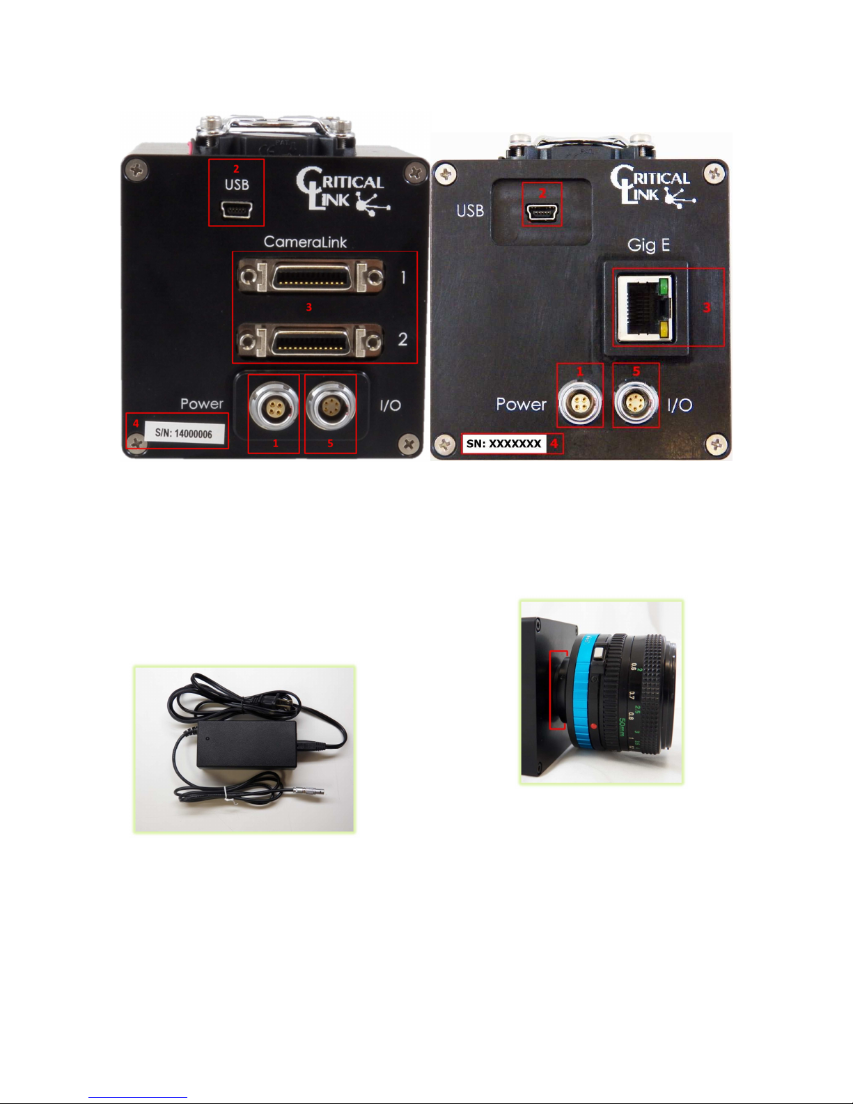
Figure 1 – MityCAM Back Panel CameraLink (Left) and Gigabit Ethernet (Right)
1) Ensure that power to the AC/DC adapter is “off”
prior to connecting it to the camera.
2) Insert the DC (4-pin) power connector into the
“Power” connector on the back panel of the
camera. (Identifier #1)
3) Insert the USB cable into the Mini B type
connector. (Identifier #2)
4) Thread supplied lens (included lens may vary) into
front plate assembly; outlined with red below.
5) (Optionally) You can connect the MityCAM camera
through the CameraLink or Gigabit Ethernet
connectors (Identifier #3). Steps 6 through 18 of
this document are for USB image acquisition
support only. Please consult the “Camera Link
Users Guide” or “MityViewer Quick Start Guide”
(Gigabit Ethernet) for further details.
 Loading...