

Critical Environment Technologies LPT-A Series Operation Manual
Operation Manual
Rev. H | 2018.04
LPT-A Analog Transmitter
www.critical-environment.com

LPT-A - Operation Manual Rev. H | 2018.04
TABLE OF CONTENTS
1 POLICIES ..........................................................................................................5
1.1 Important Note ................................................................................................5
1.2 Warranty Policy ................................................................................................6
1.3 Service Policy ...................................................................................................6
1.4 Copyrights ........................................................................................................7
1.5 Disclaimer ........................................................................................................8
1.6 Revisions ..........................................................................................................8
2 INTRODUCTION .............................................................................................9
2.1 General Description ..........................................................................................9
2.2 Key Features ...................................................................................................10
3 INSTRUMENT SPECIFICATIONS .................................................................11
3.1 Technical Speci cations ..................................................................................11
3.2 Standard Enclosure Dimensions .....................................................................14
4 SENSOR SPECIFICATIONS ...........................................................................15
4.1 List of Available Internal Sensors ....................................................................15
4.2 List of Available ESH-A Remote Sensors .........................................................17
4.3 Special Considerations for Sensors .................................................................17
4.4 Calibration Extending Firmware (CEF) and Sensor Aging................................19
5 FEATURES & FUNCTIONS ............................................................................19
5.1 Exterior Enclosure ..........................................................................................19
5.2 Interior System Layout ...................................................................................21
5.2.1 Electrochemical Sensor Board .........................................................................21
5.2.2 Solid State (Internal) Sensor Board .................................................................22
5.2.3 Solid State (Remote) Sensor Board ..................................................................23
2 © 2018 All rights reserved. Data subject to change without notice.

Rev. H | 2018.04 LPT-A - Operation Manual
6 INSTALLATION ..............................................................................................24
6.1 General Safety Warnings ................................................................................24
6.2 Protection Against Electrical Risks ..................................................................25
6.3 Protection Against Mechanical Risks ..............................................................25
6.4 System Installation ........................................................................................26
6.4.1 Wet Environment Considerations ....................................................................26
6.4.2 EMI and RF Interference Considerations ..........................................................27
6.5 Sensor Mounting Heights ...............................................................................27
6.6 Enclosure Mounting Components ..................................................................29
6.6.1 Enclosure Base ................................................................................................29
6.6.2 Enclosure Bottom ............................................................................................30
6.7 Wiring Connections ........................................................................................30
6.7.1 Power Connection ...........................................................................................31
Wiring Example: 3-Wire ..................................................................................31
Wiring Example: 4-Wire ..................................................................................31
6.7.2 Relay Connection ............................................................................................32
Wiring Example: Relay ....................................................................................32
6.7.3 Wiring LPT-A to Remote ESH Sensor (dongle style) .........................................33
Wiring Example: Remote ESH (dongle style) Sensor .......................................33
6.7.4 Wiring LPT-A to ESH-A Remote Sensor ............................................................34
Wiring Example: ESH-A Remote Sensor ..........................................................34
6.7.5 Wire Gauge vs Run Length...............................................................................35
6.7.6 Open Loop ....................................................................................................... 36
7 SYSTEM OPERATION & CONFIGURATION ................................................37
7.1 Power Up and Warm-up ................................................................................. 37
7.2 Display Select ................................................................................................. 38
7.3 Enable / Disable the Buzzer ............................................................................ 39
7.4 Selecting the Output Signal ...........................................................................39
© 2018 All rights reserved. Data subject to change without notice. 3

LPT-A - Operation Manual Rev. H | 2018.04
7.5 Fault Detection...............................................................................................40
7.6 Test Function ..................................................................................................40
7.7 Relay Operation / Setting the “Alarm” Level ...................................................41
8 CALIBRATION ................................................................................................43
8.1 Calibration Speci cations ...............................................................................43
8.1.1 Gas ..................................................................................................................43
8.1.2 Regulators & Flow ...........................................................................................44
8.1.3 Adapters..........................................................................................................44
8.1.4 Humidi er .......................................................................................................44
8.1.5 Calibration Frequency .....................................................................................44
8.1.6 Gas Testing Frequency (Bump Testing) ............................................................45
8.1.7 Sticky Gases.....................................................................................................45
8.1.8 Non-Intrusive Calibration ................................................................................45
8.2 Setting the Calibration Gas Level....................................................................46
8.3 Calibrating the Internal Sensor ......................................................................46
8.4 Calibrating an ESH-A Remote Sensor Connected to an LPT-A .........................53
8.4.1 Zero and Span Calibration of a Responsive ESH-A Remote Sensor ...................53
8.4.2 Zero Calibration of a New or Replacement ESH-A Remote Sensor .................... 53
8.5 Calibrating an Oxygen Sensor ........................................................................54
9 ACCESSORIES ...............................................................................................59
9.1 Splash Guard ..................................................................................................59
9.2 Magnetic Wand ..............................................................................................59
9.3 Metal Protective Guard ..................................................................................60
9.4 Calibration Kit ................................................................................................60
10 MAINTENANCE ..........................................................................................61
11 TROUBLE SHOOTING ................................................................................62
4 © 2018 All rights reserved. Data subject to change without notice.

Rev. H | 2018.04 LPT-A - Operation Manual
1 POLICIES
1.1 Important Note
Read and understand this manual prior to using this instrument. Carefully read the warranty policy,
service policy, notices, disclaimers and revisions on the following pages.
This product must be installed by a quali ed electrician or factor y trained technician and according
to instructions indicated in this manual. This instrument should be inspected and calibrated
regularly by a quali ed and trained technician. For more information, refer to Section 8 Calibration
and Section 10 Maintenance of this manual.
This instrument has not been designed to be intrinsically safe. For your safety, do not use it in
classi ed hazardous areas (explosion-rated environments).
INSTRUMENT SERIAL NUMBER:
______________________________________________________
PURCHASE DATE:
______________________________________________________
PURCHASED FROM:
______________________________________________________
© 2018 All rights reserved. Data subject to change without notice. 5

LPT-A - Operation Manual Rev. H | 2018.04
1.2 Warranty Policy
Critical Environment Technologies Canada Inc. (CETCI), also referred to as the manufacturer,
warrants this instrument, (excluding sensors, battery packs, batteries, pumps and lters) to be free
from defects in materials and workmanship for a period of two years from the date of purchase
from our facility. The sensors have a warranty period of one year on a pro-rated basis from
the date of purchase from our facility. If the product should become defective within this
warranty period, we will repair or replace it at our discretion.
The warranty status may be a ected if the instrument has not been used and maintained per the
instructions in this manual or has been abused, damaged, or modi ed in any way. This instrument
is only to be used for purposes stated herein. The manufacturer is not liable for auxiliary interfaced
equipment or consequential damage.
Due to ongoing research, development, and product testing, the manufacturer reserves the right to
change speci cations without notice. The information contained herein is based on data considered
accurate. However, no warranty is expressed or implied regarding the accuracy of this data.
All goods must be shipped to the manufacturer by prepaid freight. All returned goods must be
pre-authorized by obtaining a Returned Merchandise Authorization (RMA) number. Contact the
manufacturer for a number and procedures required for product transport.
1.3 Service Policy
CETCI maintains an instrument service facility at the factory. Some CETCI distributors / agents may
also have repair facilities; however, CETCI assumes no liability for service performed by anyone
other than CETCI personnel.
Repairs are warranted for 90 days after date of shipment (sensors have individual warranties).
Should your instrument require non-warranty repair, you may contact the distributor from whom it
6 © 2018 All rights reserved. Data subject to change without notice.

Rev. H | 2018.04 LPT-A - Operation Manual
was purchased or you may contact CETCI directly.
Prior to shipping equipment to CETCI, contact our o ce for an RMA #. All returned goods must be
accompanied with an RMA number.
If CETCI is to do the repair work, you may send the instrument, prepaid, to:
Attention: Service Department
Critical Environment Technologies Canada Inc.
Unit 145, 7391 Vantage Way
Delta, BC, V4G 1M3
Always include your Returned Merchandise Authorization (RMA) number, address, telephone
number, contact name, shipping / billing information, and a description of the defect as you
perceive it. You will be contacted with a cost estimate for expected repairs, prior to the performance
of any service work.
For liability reasons, CETCI has a policy of performing all needed repairs to restore the instrument to
full operating condition.
Pack the equipment well (in its original packing if possible), as we cannot be held responsible for
any damage incurred during shipping to our facility.
1.4 Copyrights
This manual is subject to copyright protection; all rights are reserved. Under international and
domestic copyright laws, this manual may not be copied or translated, in whole or in part, in any
manner or format, without the written permission of CETCI.
© 2018 All rights reserved. Data subject to change without notice. 7

LPT-A - Operation Manual Rev. H | 2018.04
1.5 Disclaimer
Under no circumstances will CETCI be liable for any claims, losses or damages resulting from or
arising out of the repair or modi cation of this equipment by a party other than CETCI service
technicians, or by operation or use of the equipment other than in accordance with the printed
instructions contained within this manual or if the equipment has been improperly maintained or
subjected to neglect or accident. Any of the forgoing will void the warranty.
Under most local electrical codes, low voltage wires cannot be run within the same conduit as line
voltage wires. It is CETCI policy that all wiring of our products meet this requirement.
It is CETCI policy that all wiring be within properly grounded (earth or safety) conduit.
1.6 Revisions
This manual was written and published by CETCI. The manufacturer makes no warranty or
representation, expressed or implied including any warranty of merchantability or tness for
purpose, with respect to this manual.
All information contained in this manual is believed to be true and accurate at the time of printing.
However, as part of its continuing e or ts to improve its products and their documentation, the
manufacturer reserves the right to make changes at any time without notice. Revised copies of this
manual can be obtained by contacting CETCI or visiting www.critical-environment.com.
Should you detect any error or omission in this manual, please contact CETCI at the following
address:
Critical Environment Technologies Canada Inc.
Unit 145, 7391 Vantage Way, Delta, BC, V4G 1M3, Canada
Toll Free: +1.877.940.8741
8 © 2018 All rights reserved. Data subject to change without notice.

Rev. H | 2018.04 LPT-A - Operation Manual
Telephone: +1.604.940.8741
Fax: +1.604.940.8745
Email: marketing@cetci.com
Website: www.critical-environment.com
In no event will CETCI, its o cers or employees be liable for any direct, special, incidental or
consequential damages resulting from any defect in any manual, even if advised of the possibility
of such damages.
2 INTRODUCTION
2.1 General Description
Thank you for purchasing our LPT-A Analog Transmitter.
The LPT-A transmitter is a single sensor, analog transmitter available with a wide range of sensors
and sensor types of continuous monitoring of gases or oxygen in non-hazardous (non-explosion
rated) environments such as commercial HVAC and light industrial applications.
Operating as an analog transmitter or a stand-alone xed system, the LPT-A o ers a back lit LCD
display, an internal audible alarm, one dry relay contact, a jumper selectable 4-20 mA or 0 - 10 VDC
analog output signal, 3-wire VDC or 4-wire VAC power, a thermal resetting fuse and temperature
compensation all in a RoHS compliant package. It comes in a standard with a water / dust tight,
corrosion resistant ABS / polycarbonate enclosure with a hinged, secured door. With the optional
splash guard installed, the enclosure is IP54 rated and ideal for use in water spray or washdown
applications.
LPT-A transmitter is available with internal or remote sensor options. All LPT-A transmitters operate
by di usion. The sensors utilized in this device are accurate enough to measure to Occupational
© 2018 All rights reserved. Data subject to change without notice. 9

LPT-A - Operation Manual Rev. H | 2018.04
Health & Safety (OHS) hazardous levels for toxic gases.
If after reading through the manual, you have any questions, please do not hesitate to contact our
service department for technical support.
2.2 Key Features
• Single channel
• Wide range of internal sensor types including electrochemical, solid state and TVOC
• Remote combustible and PID sensor options
• Graphic LCD display (user selectable function)
• Audible alarm
• 3-wire VDC or 4-wire VAC power
• 24 volt DC or AC power (nominal)
• Linear 4 - 20 mA or 0 - 10 volt output signal
• 1 dry contact relay, 30 volt 2 amps maximum
• Standard water / dust tight, corrosion resistant enclosure (drip proof). With optional splash
guard installed, the enclosure is IP54 rated.
• Copper coated interior to reduce RF interference
• RoHS compliant circuit boards
• Includes sensor Calibration Extending Firmware (CEF) for some electrochemical sensors
• Auto resetting fuse
10 © 2018 All rights reserved. Data subject to change without notice.

Rev. H | 2018.04 LPT-A - Operation Manual
3 INSTRUMENT SPECIFICATIONS
3.1 Technical Speci cations
MECHANICAL
Enclosure
Weight 400 g (14 oz)
Size 127 mm x 127 mm x 53.34 mm (5.0 in x 5.0 in x 2.1 in )
ELECTRICAL
Power Requirement
3-wire mode
4-wire mode
Current Draw 125 mA @ 24 VDC
Wiring
Fuses Automatic resetting thermal
ABS / Polycarbonate, IP54 rating with splash guard installed.
Copper coated interior to reduce RF interference.
16 - 30 VDC, 3 W, Class 2
12 - 27 VAC, 50-60 Hz, 3 VA, Class 2
Use Class 2 transformer. See Section 6.7 Wiring Connections.
VDC (or ground referenced AC) three conductor shielded 18 awg
(or larger) stranded within conduit
VAC four conductor shielded 18 awg stranded within conduit
(refer to Section 6.7.5 Wire Gauge vs. Run Length)
© 2018 All rights reserved. Data subject to change without notice. 11

LPT-A - Operation Manual Rev. H | 2018.04
USER INTERFACE
Graphic LCD, grey border. Text prompting for calibration operation
Display
and fault indications. Installer con gurable to suppress all other
displays.
Magnetic Sensors
Using the magnetic wand to initiate calibration without opening
enclosure.
INPUTS / OUTPUTS
Linear 4 - 20 mA
Maximum 216 Ω load (wiring plus termination resistor) @ 12 VDC
Outputs
Maximum 316 Ω load (wiring plus termination resistor) @ 12 VAC
Voltage 0 - 10 volt
Minimum 1k ohm load
Relay One SPDT dry contact relay, rated 2A @ 30V maximum
ENVIRONMENTAL
-20°C to 40°C (-4°F to 104°F)
NOTE: Low temperature option available to -40°C (-40°F) (Sensor
Operating Temperature
dependent, some extremely cold applications may require a small
internal silicone heater to maintain temperature stability for sensor.
Contact CETCI for details and pricing.)
Operating Humidity 15 - 90% RH non-condensing
12 © 2018 All rights reserved. Data subject to change without notice.

Rev. H | 2018.04 LPT-A - Operation Manual
CERTIFICATIONS
Model: LPT-A-XXX
S/N: LPTAE1601H00374
Rating: 16-30 VDC, 3W, Class 2
12-27 VAC, 50-60 Hz 3VA, Class 2
CERTIFIED FOR ELECTRIC SHOCK & ELECTRICAL FIRE HAZARD ONLY. LA CERTIFICATION ACNOR
COUVRE UNIQUEMENT LES RISQUES DE CHOC ELECTRIQUE ET D’INCENDIE D’ORIGINE ELECTRIQUE.
Conforms to: CSA-C22.2 No. 205-M1983 (R2009), UL508 (Edition 17):2007
Conforms to: EMC Directive 2004/108/EC, EN 50270:2006, Type 1, EN61010
Conforms to: FCC. This device complies with Part 15 of the FCC Rules. Operation is subject to
the following two conditions: (1) This device may not cause harmful interference, and (2) this
device must accept any interference received, including interference that may cause undesired
operation.
© 2018 All rights reserved. Data subject to change without notice. 13
LPT-A - Operation Manual Rev. H | 2018.04
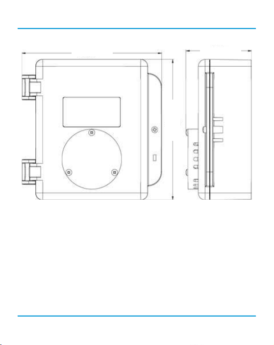
3.2 Standard Enclosure Dimensions
127 mm (5.0 in )
127 mm (5.0 in )
Above dimensions are shown with optional splash guard. Without splash guard, thickness is
53.34 mm (2.1 in). The area required for enclosure door to be open 90 degrees is 178 mm (7 in) or
254 mm (10 in) for fully open. With the splash guard, the enclosure has an IP54 rating.
NOTE: During calibration, the sensor response time will be slower with a splash guard installed.
NOTE: Splash guard is not available for transmitters with internal electrochemical Ozone (O3),
Hydrogen Chloride (HCL) or Chlorine (Cl2) sensors.
14 © 2018 All rights reserved. Data subject to change without notice.
61 mm (2.4 in )

Rev. H | 2018.04 LPT-A - Operation Manual
4 SENSOR SPECIFICATIONS
4.1 List of Available Internal Sensors
Internal Electrochemical
Sensors
Ammonia (NH3) LPT-A-NH3 0 - 500 ppm 2 years
Carbon Monoxide (CO) LPT-A-COA 0 - 200 ppm 3 years
Carbon Monoxide (CO) LPT-A-COB 0 - 200 ppm 6 years
Chlorine (Cl2) LPT-A-CL2 0 - 5 ppm 3 years
Chlorine Dioxide (ClO2) LPT-A-CLO2 0 - 1.0 ppm 2 years
Ethylene (C2H4) LPT-A-C2H4 0 - 200 ppm 2 years
Ethylene Oxide (C2H4O) LPT-A-EETO 0 - 20 ppm 2 years
Fluorine (F2) LPT-A-F2 0 - 2 ppm 1 - 2 years
Formaldehyde (CH2O) LPT-A-CH2O 0 - 5 ppm 2 years
Hydrogen (H2) LPT-A-EH2 0 - 2,000 ppm 2 years
Hydrogen Chloride (HCl) LPT-A-HCL 0 - 20 ppm 2 years
Hydrogen Cyanide (HCN) LPT-A-HCN 0 - 100 ppm 2 years
Hydrogen Fluoride (HF) LPT-A-HF 0 - 10.0 ppm 1 - 2 years
Hydrogen Sulphide (H2S) LPT-A-H2S 0 - 50 ppm 2+ years
Hydrogen Sulphide (H2S) LPT-A-H2SB 0 - 50 ppm 5+ years
Nitric Oxide (NO) LPT-A-NO 0 - 100 ppm 2 years
Part Number Range Lifespan
© 2018 All rights reserved. Data subject to change without notice. 15

LPT-A - Operation Manual Rev. H | 2018.04
Internal Electrochemical
Part Number Range Lifespan
Sensors continued...
Nitrogen Dioxide (NO2) LPT-A-NO2A 0 - 10 ppm 3 years
Nitrogen Dioxide (NO2) LPT-A-NO2B 0 - 10 ppm 6 years
Oxygen (O2) LPT-A-O2 0 - 25% Vol 3 years
Ozone (O3) LPT-A-O3 0 - 2 ppm 2 years
Phosphine (PH3) LPT-A-PH3 0 - 5 ppm 2 years
Silane (SiH4) LPT-A-SIH4 0 - 20 ppm 2 years
Sulphur Dioxide (SO2) LPT-A-SO2 0 - 20 ppm 2+ years
Internal Solid State Sensors Part Number Range Lifespan
Refrigerant (R22) LPT-A-SR22 0 - 2,000 ppm 5 years
Refrigerant (R134A) LPT-A-SR134A 0 - 2,000 ppm 5 years
Refrigerant (R402A) LPT-A-SR402A 0 - 2,000 ppm 5 years
Refrigerant (R404A) LPT-A-SR404A 0 - 2,000 ppm 5 years
Refrigerant (R407C) LPT-A-SR407C 0 - 2,000 ppm 5 years
Refrigerant (R410A) LPT-A-SR410A 0 - 2,000 ppm 5 years
Refrigerant (R422D) LPT-A-SR422D 0 - 2,000 ppm 5 years
Refrigerant (R438A) LPT-A-SR438A 0 - 2,000 ppm 5 years
Refrigerant (R438A) LPT-A-SR438A 0 - 2,000 ppm 5 years
Refrigerant (R507) LPT-A-SR507 0 - 2,000 ppm 5 years
TVOC (Isobutylene) LPT-A-STVOC 0 - 500 ppm 5 years
16 © 2018 All rights reserved. Data subject to change without notice.

Rev. H | 2018.04 LPT-A - Operation Manual
Internal Catalytic
Part Number Range Lifespan
(Combustible) Sensors
Hydrogen (H2) LPT-A-CH2-100 0 - 100% LEL 5 years
Methane (CH4) LPT-A-CCH4-100 0 - 100% LEL 5 years
Propane (C3H8) LPT-A-CC3H8-100 0 - 100% LEL 5 years
4.2 List of Available ESH-A Remote Sensors
ESH-A Remote Sensors - Catalytic (Combustible)
Hydrogen (H2) ESH-A-CH2-100 0 - 100% LEL 5 years
Methane (CH4) ESH-A-CCH4-100 0 - 100% LEL 5 years
Propane (C3H8) ESH-A-CC3H8-100 0 - 100% LEL 5 years
ESH-A Remote Sensors - TVOC PID
TVOC PID ESH-A-SPL 0 - 30 ppm
TVOC PID ESH-A-SPH 0 - 300 ppm
usage / application
dependent
4.3 Special Considerations for Sensors
If you install the LPT-A when it arrives, the sensor will not require a long warm up period (about
5 minutes for Ammonia and Nitrogen dioxide and 2 minutes for all the others). The sensors go
through a burn in period at our factory so they are ready for operation upon arrival. If the device
is not installed within two weeks of delivery, the sensor may require a longer warm up time to
stabilize (approximately 48 hours) and provide accurate readings.
© 2018 All rights reserved. Data subject to change without notice. 17

LPT-A - Operation Manual Rev. H | 2018.04
After installing an LPT-A with an Oxygen sensor, leave it to warm up for 2 hours before looking at
the readings.
After a substantial warm up period, an Ethylene Oxide sensor should be zeroed on site if the
ambient temperature is above 22°C (71.6°F). This particular sensor has a drift factor that can be as
much as 1 ppm if the temperature rises to 25°C (77°F). With the low set point you could experience
false alarms.
For an R11 refrigerant sensor, allow 30 minutes after power up before considering the LPT-A’s
readings valid. The sensor’s response to R11 refrigerant and to humidity levels can a ect the
readings of the LPT-A and can take up to 30 minutes after power up to recover and stabilize.
During calibration, when owing span gas on an Ammonia sensor, if the reading climbs higher than
the calibration point after applying gas for 3 minutes, use that reading as the calibration point. It
should be around 300 ppm.
Ozone sensors are reactive to temperature changes and will drift.
Silicone, lead and chlorinated hydrocarbon vapours can poison catalytic sensors.
A bump test will help you determine if a sensor requires calibration. If the sensor still does not
respond as it should after a successful calibration, it probably requires replacing.
Temperature a ects calibration. It is impor tant to ensure the gas is at the appropriate temperature
during calibration. If the sensor is being used in an extreme temperature range, calibration should
be done in that same temperature range.
18 © 2018 All rights reserved. Data subject to change without notice.
Rev. H | 2018.04 LPT-A - Operation Manual
4.4 Calibration Extending Firmware (CEF) and
Sensor Aging
Some LPT-A systems with certain electrochemical sensors have been programmed with our
Calibration Extending Firmware (CEF). This rmware takes into consideration the aging of the
sensors so that less frequent calibrations are acceptable in less-critical applications such as parking
garages. The system tracks the age of the sensor and automatically compensates for the reduced
output of the sensor as it ages.
5 FEATURES & FUNCTIONS
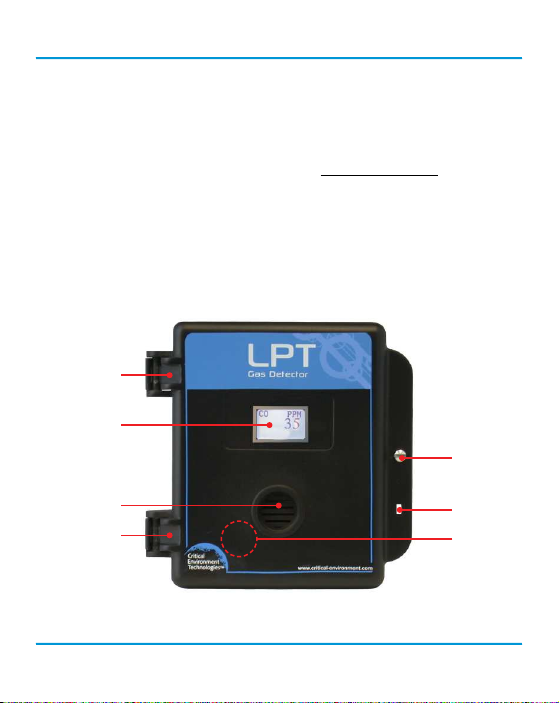
5.1 Exterior Enclosure
Œ
•
Ž
•
Œ
© 2018 All rights reserved. Data subject to change without notice. 19
•
‘

LPT-A - Operation Manual Rev. H | 2018.04
NUMBER FEATURE FUNCTION
Œ
•
Ž
•
•
‘
Door Hinge Secures door
Display with gray border
Door Screw Secures door
Sensor Opening Allows gas di usion into sensor
Padlock Opening For security padlock
Magnetic Calibration Trigger Point To enter calibration
Indicates transmitter operation
20 © 2018 All rights reserved. Data subject to change without notice.
 Loading...