

Page 1
Operation Manual
www.critical-environment.com
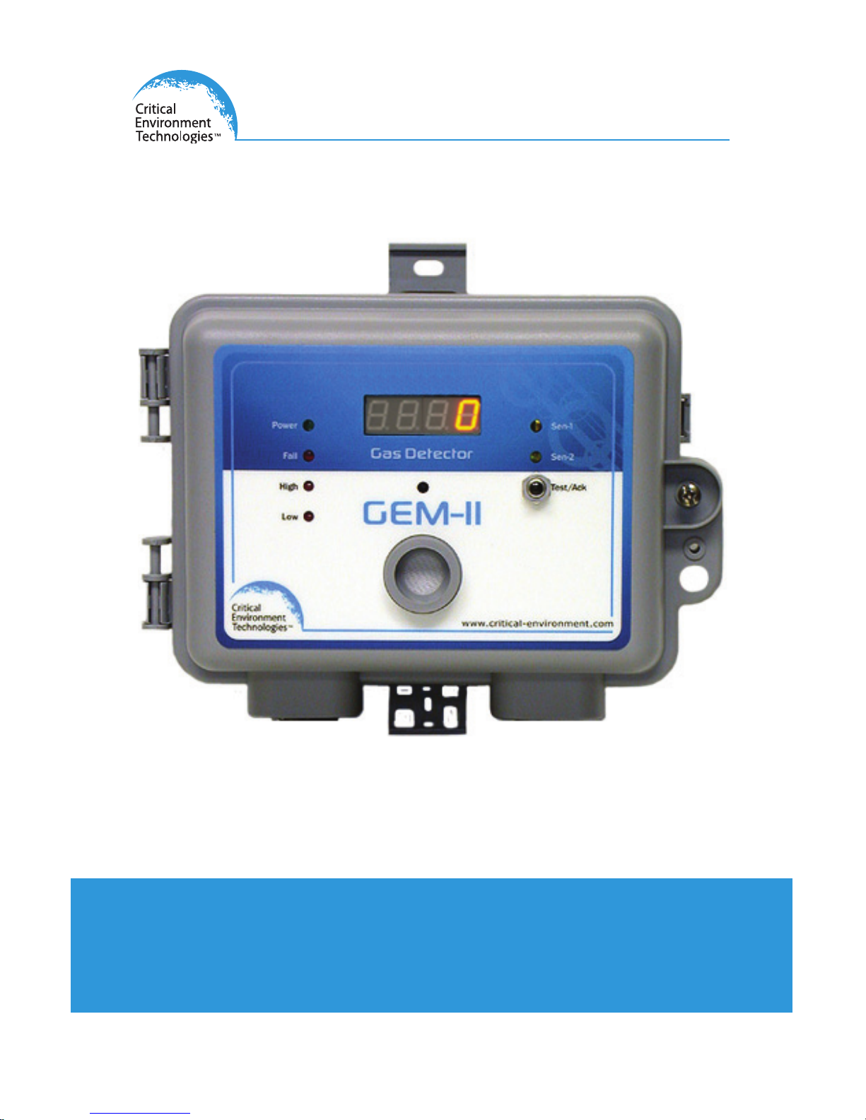
GEM-II Self Contained Gas Detector
Rev. E | 2014.10
Page 2

2 © 2014 All rights reserved. Data subject to change without notice.
GEM-II - Operation Manual Rev. E | 2014.10
TABLE OF CONTENTS
1 POLICIES .................................................................................................................. 5
1.1 Important Note ..............................................................................................................5
1.2 Warranty Policy ..............................................................................................................6
1.3 Service Policy .................................................................................................................6
1.4 Copyrights ......................................................................................................................7
1.5 Disclaimer ......................................................................................................................7
1.6 Revisions ........................................................................................................................8
2 INTRODUCTION ..................................................................................................... 9
2.1 General Description .......................................................................................................9
2.2 Key Features...................................................................................................................9
2.3 Model Designations .....................................................................................................10
2.3.1 Type A – Single Channel ............................................................................................... 10
2.3.2 Type B – Single Channel Controller ............................................................................... 11
2.3.3 Type D – Dual Channel .................................................................................................. 12
2.3.4 Type E– Dual Channel ................................................................................................... 13
3 INSTRUMENT SPECIFICATIONS .........................................................................13
3.1 Technical Specications................................................................................................13
3.2 Standard Enclosure Dimensions ...................................................................................16
3.3 Watertight Enclosure Dimensions ................................................................................16
4 SENSOR SPECIFICATIONS ...................................................................................17
4.1 Sensor Specications ...................................................................................................17
4.2 Remote Sensor Specications ......................................................................................18
4.3 Calibration Extending Firmware (CEF) and Sensor Aging .............................................18
5 FEATURES & FUNCTIONS ....................................................................................19
5.1 Standard Exterior Enclosure .........................................................................................19
5.2 Watertight Exterior Enclosure ......................................................................................20
5.3 Interior System Layout .................................................................................................21
6 INSTALLATION ...................................................................................................... 22
6.1 AC and DC Wiring .........................................................................................................22
6.1.1 Wiring Example 1 .......................................................................................................... 22
6.1.2 Wiring Example 2 .......................................................................................................... 23
Page 3

© 2014 All rights reserved. Data subject to change without notice. 3
Rev. E | 2014.10 GEM-II - Operation Manual
6.1.3 Wiring Example 3 - INCORRECT ..................................................................................... 23
6.1.4 Wiring Example 4 .......................................................................................................... 24
6.1.5 Wiring Example 5 (J2 Removed) ................................................................................... 24
6.1.6 Wiring Example 6 (J2 Removed) ................................................................................... 25
6.2 Sensor Mounting Heights ............................................................................................25
6.3 Standard Enclosure Mounting Components .................................................................26
6.3.1 Enclosure Base .............................................................................................................. 26
6.3.2 Enclosure Top ................................................................................................................ 26
6.3.3 Enclosure Bottom ......................................................................................................... 27
6.4 Remote Sensor Connection ..........................................................................................27
6.5 Wiring Connections ......................................................................................................28
6.5.1 Types A, B and D ............................................................................................................ 28
6.5.2 Type E............................................................................................................................ 28
6.6 Important Notes for Wiring ..........................................................................................29
6.7 System Installation ......................................................................................................29
6.7.1 Low Voltage Power ........................................................................................................29
6.7.2 Wiring to Remote Sensor .............................................................................................. 30
6.7.3 Voltage to Remote Sensors ........................................................................................... 30
6.7.4 Relay Connections......................................................................................................... 30
6.8 Installation Examples ...................................................................................................31
6.8.1 Type A with Internal Sensor and Enclosed Transformer ................................................. 31
6.8.2 Type B with Remote Sensor or Analog Transmitter ........................................................ 32
6.8.3 Type D with One Internal & One Remote Sensor ............................................................ 33
6.8.4 Type E with Two Internal Sensors .................................................................................. 34
7 OPERATION ...........................................................................................................34
7.1 System Operation ........................................................................................................34
7.2 Test Functions ..............................................................................................................35
7.3 Dip Switch Package ......................................................................................................36
7.4 Internal Audible Alarm Operation ................................................................................37
7.5 Jumpers .......................................................................................................................37
7.6 Adjusting Alarm Set Points ..........................................................................................39
7.6.1 Voltage Reference Table for Alarm Settings ................................................................... 41
7.7 Time Delays for Relay Operations .................................................................................42
7.7.1 Procedure for Setting Time Delays .................................................................................44
7.8 Temperature Display - Unit of Measure ........................................................................45
Page 4

4 © 2014 All rights reserved. Data subject to change without notice.
GEM-II - Operation Manual Rev. E | 2014.10
7.9 Latching Relay Functions .............................................................................................45
7.10 LED Digital Display .....................................................................................................46
8 CALIBRATION ........................................................................................................47
8.1 Calibration Specications .............................................................................................47
8.1.1 Gas ................................................................................................................................ 47
8.1.2 Exception ...................................................................................................................... 47
8.1.3 Regulators & Flow ......................................................................................................... 47
8.1.4 Adapters ....................................................................................................................... 47
8.2 Calibrating Sensors ......................................................................................................48
8.2.1 Calibration Frequency ................................................................................................... 48
8.3 Calibration Procedure ...................................................................................................48
8.4 Calibrating the Internal Sensor ....................................................................................49
8.4.1 Setting Span Gas Value ................................................................................................. 49
8.4.2 Calibrating the Null (Zero) Value ................................................................................... 49
8.4.3 Calibrating the Span Gas ............................................................................................... 50
8.5 Calibrating Second Internal Sensor ..............................................................................51
8.6 Calibrating Remote Sensor ..........................................................................................51
8.6.1 Setting Span Gas Value for Remote Sensor ................................................................... 51
8.6.2 Calibrating the Null (Zero) Value ................................................................................... 51
8.6.3 Calibrating the Span Gas ............................................................................................... 52
8.7 Calibrating 4-20 mA for Incoming Analog Transmitter ................................................53
8.7.1 Using a Current Source to Calibrate the Null .................................................................. 53
8.7.2 Using a Current Source to Calibrate the Span ................................................................ 53
8.7.3 Using a CETCI Analog Transmitter to Calibrate the Null .................................................. 54
8.7.4 Using a CETCI Analog Transmitter to Calibrate the Span ................................................ 54
8.8 Forcing Calibration ......................................................................................................55
9 ACCESSORIES .......................................................................................................56
9.1 Calibration Kit ..............................................................................................................56
9.2 Metal Protective Guard ................................................................................................56
10 MAINTENANCE ..................................................................................................57
Page 5

© 2014 All rights reserved. Data subject to change without notice. 5
Rev. E | 2014.10 GEM-II - Operation Manual
1 POLICIES
1.1 Important Note
Read and understand this manual prior to using this instrument. Carefully read the warranty
policy, service policy, notices, disclaimers and revisions on the following pages.
This product must be installed by a qualied electrician or factory trained technician and
according to instructions indicated in this manual. This instrument should be inspected and
calibrated regularly by a qualied and trained technician. For more information, refer to Sections
8 Calibration and 10 Maintenance of this manual.
This instrument has not been designed to be intrinsically safe. For your safety, do not use it in
classied hazardous areas (explosion-rated environments).
INSTRUMENT SERIAL NUMBER:
__________________________________________________________
PURCHASE DATE:
__________________________________________________________
PURCHASED FROM:
__________________________________________________________
Page 6

6 © 2014 All rights reserved. Data subject to change without notice.
GEM-II - Operation Manual Rev. E | 2014.10
1.2 Warranty Policy
• Disconnect power before servicing
• Caution: More than one live circuit
• Supply: 24 V (nominal, 50 or 60 Hz)
• Certied for electrical shock and electrical re hazard only
Critical Environment Technologies Canada Inc. (CETCI), also referred to as the manufacturer,
warrants this instrument, (excluding sensors, battery packs, batteries, pumps and lters) to be
free from defects in materials and workmanship for a period of two years from the date of
purchase from our facility. The sensors have a warranty period of one year on a pro-rated
basis from the date of purchase from our facility. If the product should become defective
within this warranty period, we will repair or replace it at our discretion.
The warranty status may be aected if the instrument has not been used and maintained per
the instructions in this manual or has been abused, damaged, or modied in any way. This
instrument is only to be used for purposes stated herein. The manufacturer is not liable for
auxiliary interfaced equipment or consequential damage.
Due to ongoing research, development, and product testing, the manufacturer reserves the
right to change specications without notice. The information contained herein is based on data
considered accurate. However, no warranty is expressed or implied regarding the accuracy of this
data.
All goods must be shipped to the manufacturer by prepaid freight. All returned goods must be
pre-authorized by obtaining a Returned Merchandise Authorization (RMA) number. Contact the
manufacturer for a number and procedures required for product transport.
1.3 Service Policy
CETCI maintains an instrument service facility at the factory. Some CETCI distributors / agents
may also have repair facilities; however, CETCI assumes no liability for service performed by
anyone other than CETCI personnel.
Repairs are warranted for 90 days after date of shipment (sensors have individual warranties).
Should your instrument require non-warranty repair, you may contact the distributor from
whom it was purchased or you may contact CETCI directly.
Page 7

© 2014 All rights reserved. Data subject to change without notice. 7
Rev. E | 2014.10 GEM-II - Operation Manual
Prior to shipping equipment to CETCI, contact our oce for an RMA #. All returned goods must
be accompanied with an RMA number.
If CETCI is to do the repair work, you may send the instrument, prepaid, to:
Attention: Service Department
Critical Environment Technologies Canada Inc.
Unit 145, 7391 Vantage Way
Delta, BC, V4G 1M3
Always include your Returned Merchandise Authorization (RMA) number, address, telephone
number, contact name, shipping / billing information, and a description of the defect as
you perceive it. You will be contacted with a cost estimate for expected repairs, prior to the
performance of any service work.
For liability reasons, CETCI has a policy of performing all needed repairs to restore the instrument
to full operating condition.
Pack the equipment well (in its original packing if possible), as we cannot be held responsible for
any damage incurred during shipping to our facility.
1.4 Copyrights
This manual is subject to copyright protection; all rights are reserved. Under international and
domestic copyright laws, this manual may not be copied or translated, in whole or in part, in any
manner or format, without the written permission of CETCI.
1.5 Disclaimer
Under no circumstances will CETCI be liable for any claims, losses or damages resulting from or
arising out of the repair or modication of this equipment by a party other than CETCI service
technicians, or by operation or use of the equipment other than in accordance with the printed
instructions contained within this manual or if the equipment has been improperly maintained
or subjected to neglect or accident. Any of the foregoing will void the warranty.
Under most local electrical codes, low voltage wires cannot be run within the same conduit as
line voltage wires. It is CETCI policy that all wiring of our products meet this requirement.
It is CETCI policy that all wiring be within properly grounded (earth or safety) conduit.
Page 8

8 © 2014 All rights reserved. Data subject to change without notice.
GEM-II - Operation Manual Rev. E | 2014.10
1.6 Revisions
This manual was written and published by CETCI. The manufacturer makes no warranty or
representation, expressed or implied including any warranty of merchantability or tness for
purpose, with respect to this manual.
All information contained in this manual is believed to be true and accurate at the time
of printing. However, as part of its continuing eorts to improve its products and their
documentation, the manufacturer reserves the right to make changes at any time without
notice. Revised copies of this manual can be obtained by contacting CETCI or visiting
www.critical-environment.com.
Should you detect any error or omission in this manual, please contact CETCI at the following
address:
Critical Environment Technologies Canada Inc.
Unit 145, 7391 Vantage Way, Delta, BC, V4G 1M3, Canada
Toll Free: +1.877.940.8741
Telephone: +1.604.940.8741
Fax: +1.604.940.8745
Email: [email protected]
Website: www.critical-environment.com
In no event will CETCI, its ocers or employees be liable for any direct, special, incidental
or consequential damages resulting from any defect in any manual, even if advised of the
possibility of such damages.
Page 9

© 2014 All rights reserved. Data subject to change without notice. 9
Rev. E | 2014.10 GEM-II - Operation Manual
2 INTRODUCTION
2.1 General Description
Thank you for purchasing our GEM-II self-contained gas detector.
The GEM series gas detection systems are economical, self-contained, gas detectors for nonhazardous (non-explosion rated) commercial applications. They are available in two basic
congurations: one sensor models and two sensor models. The sensors can be congured as one
integral (A-type), one remote (B-type), one integral and one remote (D-type), or two integral
(E-type).
A basic system provides one set of LED indicating lights representing “Power”, “Fail”, “Low
(Warning) Gas Alarm”, ‘High Gas Alarm”, an integral audible alarm with door mounted silence
push-button, audible time delay, eld settable relay time delays and two alarm relays. In either
system, the LED lights provide visual indication of the status of each channel (Int = internal
sensor, Ext = external sensor or second channel).
Gas specic electrochemical sensors for toxic gases and Oxygen (O2) are available as are MOS
solid-state sensors for refrigerants and catalytic sensors for combustible gases. All GEM integral
sensors are packaged as plug-in “smart” sensor modules to reduce eld maintenance time.
If after reading through the manual, you have any questions, please do not hesitate to contact
our service department for technical support.
2.2 Key Features
• Single or dual channel
• Network multiple units
• Integral plug & play “smart” sensors or remote sensors
• 4 – 20 mA linear output signal
• Three conduit entry ports
• Thermal resetting fuse
• LED light indicators
• Two 5-amps SPDT relays
• RoHS compliant circuit boards
• CSA & UL certied
Page 10
10 © 2014 All rights reserved. Data subject to change without notice.
GEM-II - Operation Manual Rev. E | 2014.10
2.3 Model Designations
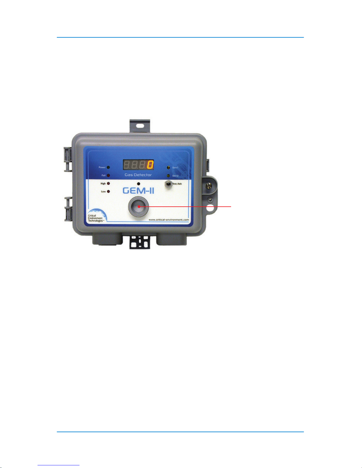
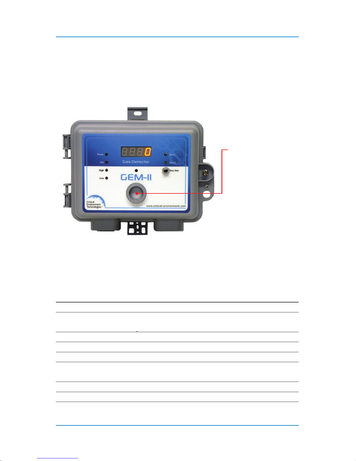
2.3.1 Type A – Single Channel
Choices for GEM-A:
• One integral electrochemical sensor.
NOTES: Optional LED digital display is shown in the photo.
Opening for integral sensor
(example: CO) to monitor
diused air and gas.
Page 11
© 2014 All rights reserved. Data subject to change without notice. 11
Rev. E | 2014.10 GEM-II - Operation Manual
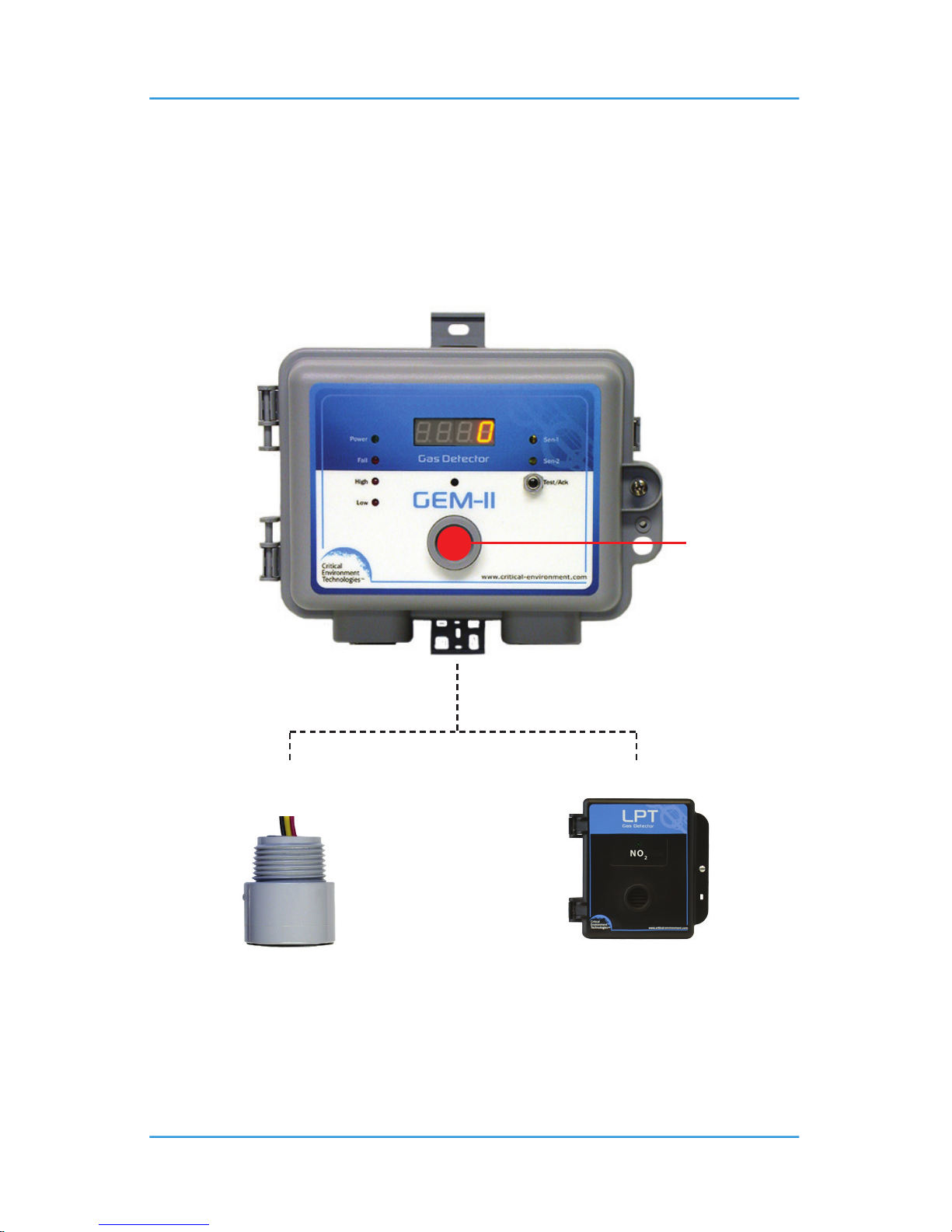
2.3.2 Type B – Single Channel Controller
Choices for GEM-B:
• One remote catalytic or solid state sensor
• One remote LPT-A or LPT series analog transmitter
NOTES: Optional LED digital display is shown in the photo.
Wiring requirements:
• 3-conductor, 18 gauge to remote sensor.
• 3-conductor shielded to remote analog transmitter.
Plug covering
sensor opening
Remote catalytic or
solid state sensor
Remote analog transmitterOR
Page 12
12 © 2014 All rights reserved. Data subject to change without notice.
GEM-II - Operation Manual Rev. E | 2014.10
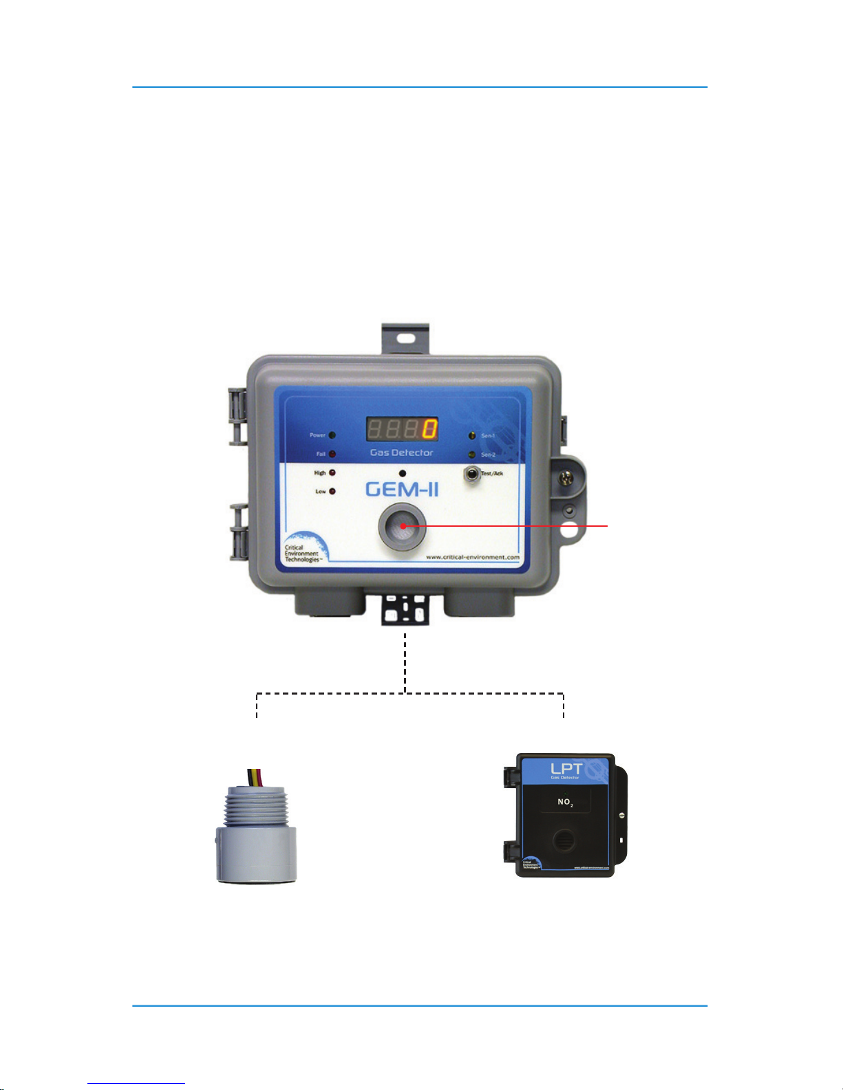
2.3.3 Type D – Dual Channel
Choices for GEM-D:
• One integral electrochemical sensor (Channel1) PLUS one remote catalytic or solid state
sensor (Channel 2).
• One integral electrochemical sensor (Channel1) PLUS one remote LPT-A or LPT series
analog transmitter (Channel 2).
NOTES: Optional LED digital display is shown in the photo.
Wiring requirements:
• 3-conductor, 18 gauge to remote sensor.
• 3-conductor shielded to remote analog transmitter.
Opening for
integral sensor
to monitor
diused by air
and gas.
Remote catalytic or
solid state sensor
Remote analog transmitterOR
Page 13
© 2014 All rights reserved. Data subject to change without notice. 13
Rev. E | 2014.10 GEM-II - Operation Manual
2.3.4 Type E – Dual Channel
Choices for GEM-E:
• Two integral electrochemical sensors (Channel 1 & 2)
NOTES: Optional LED digital display is shown in the photo.
3 INSTRUMENT SPECIFICATIONS
3.1 Technical Specications
GAS TYPE
Carbon Monoxide (CO)
Combustible Gases (catalytic)
Hydrogen (H
2
), Methane (CH4), Propane (C3H8)
Nitrogen Dioxide (NO
2
)
Nitric Oxide (NO)
Oxygen (O
2
)
Refrigerants (solid state)
R22, R134A, R402A, R404A, R407C, R410A, R422A, R422D, R507A
Sulphur Dioxide (SO
2
)
TVOCs (solid state)
Opening for TWO integral
sensors to monitor diused
air and gas.
Common application is
engine exhaust: gasoline
or diesel sensors are both
integral in the GEM type E
version.
Page 14

14 © 2014 All rights reserved. Data subject to change without notice.
GEM-II - Operation Manual Rev. E | 2014.10
MECHANICAL
Standard Enclosure General purpose PVC
Standard Weight 600 g (1.2 lb)
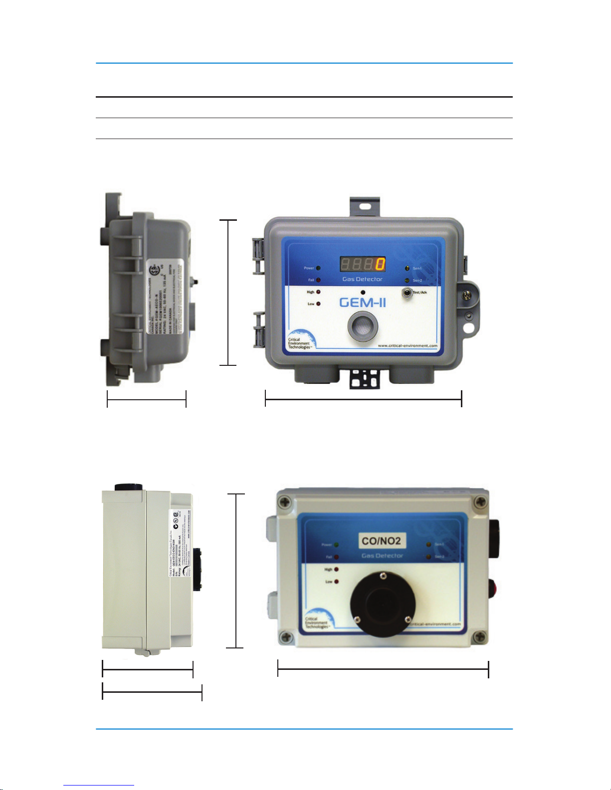
Standard Size 5.3” x 6.8” x 2.6” (135 mm x 173 mm x 66 mm)
Watertight Enclosure Water / dust tight polycarbonate
Watertight Weight 700 g (1.4 lb)
Watertight Size 5.1” x 7.1” x 4.0” (130 mm x 181 mm x 102 mm)
ELECTRICAL
Power Requirement 15 - 30 VDC or 12 - 28 VAC
Current Draw Approximately 125 mA
Wiring
VDC three-conductor shielded
VAC four-conductor shielded
Circuit
Analog design with microprocessor and user settable time
delays, accessible with DIP switches on circuit board.
Fuse Automatic resetting thermal
INPUT / OUTPUT
Outputs Linear 4 - 20 mA (single)
Distance
Maximum 500 ft between controller and remote solid state
sensor using minimum 18 gauge wire.
Relays
Two S.P.D.T. dry contact relays, rated 5 amps @ 240 VAC.
NOTES:
1. System is congured such that all relays are “FAIL SAFE”
(relay coils are always energized in non-alarm state).
2. Relays are “common” to both channels (activated by either
channel).
USER INTERFACE
Display
Common set of LED indicating lights for “Power”, “Fail”, “Low
(Warning) Gas Alarm”, “High Gas Alarm”
Page 15

© 2014 All rights reserved. Data subject to change without notice. 15
Rev. E | 2014.10 GEM-II - Operation Manual
Audible
Integral piezo audible alarm rated 80 dB @ 10’ c/w door mounted
silence push-button.
NOTES: Audible alarm & silence push-button are right side
mounted on water tight enclosure.
Time Delays
Delay “ON” (on make),
DIP switch
Delay “OFF” (on break),
DIP switch
Audible (on make),
DIP switch
Low alarm relay: 2 minutes
High alarm relay: 5 minutes
Also known as “minimum run time”
Low alarm relay: 10 minutes
High alarm relay: not available
10 minutes
NOTES: Time delays can be changed by user.
Reference Section 7 Operation. DIP switches are still used to
enable or disable time delays.
SENSOR
Enclosure Molded PVC
Integral
Electrochemical only
NOTES: All integral electrochemical gas sensors are packaged as
“smart” sensor modules.
Remote
Solid State sensor for refrigerants and TVOCs
Catalytic sensor for combustible gases
Analog transmitter, LPT-A or LPT (4 – 20 mA signal)
ENVIRONMENTAL (sensor dependant)
Operating Temperature -20°C to 50°C (-5°F to 120°F)
Operating Humidity 15 - 90% RH non-condensing
Page 16
16 © 2014 All rights reserved. Data subject to change without notice.
GEM-II - Operation Manual Rev. E | 2014.10
CERTIFICATION
CSA Certied
UL Certied
3.2 Standard Enclosure Dimensions
3.3 Watertight Enclosure Dimensions
5.25” (133 mm)
2.625” (67 mm) 6.75” (172 mm)
5.13” (130 mm)
7.13” (181 mm)4.0” (102 mm)
4.38” (102 mm)
Page 17

© 2014 All rights reserved. Data subject to change without notice. 17
Rev. E | 2014.10 GEM-II - Operation Manual
4 SENSOR SPECIFICATIONS
4.1 Common Sensor Specications
Carbon Monoxide (CO)
Type Electrochemical
Response Time <30 seconds to 90% of signal response
Operating Temperature 0°C to 50°C (32°F to 120°F)
Repeatability ± 10% of set point
Life Span 3 years in air (under normal conditions)
Nitric Oxide (NO)
Type Electrochemical
Response Time <30 seconds to 90% of signal response
Operating Temperature 0°C to 50°C (32°F to 120°F)
Repeatability ± 10% of set point
Life Span 2 years in air (under normal conditions)
Nitrogen Dioxide (NO
2
)
Type Electrochemical
Response Time <30 seconds to 90% of signal response
Operating Temperature 0°C to 50°C (32°F to 120°F)
Repeatability ± 10% of set point
Life Span 3 years in air (under normal conditions)
Sulphur Dioxide (SO
2
)
Type Electrochemical
Response Time <30 seconds to 90% of signal response
Operating Temperature 0°C to 50°C (32°F to 120°F)
Repeatability ± 10% of set point
Life Span 2+ years in air (under normal conditions)
Page 18

18 © 2014 All rights reserved. Data subject to change without notice.
GEM-II - Operation Manual Rev. E | 2014.10
Temperature (°C or °F)
Range -20°C to 40°C (-4°F to 104°F)
4.2 Remote Sensor Specications
1. Remote sensor module: The remote sensor housing accommodates one catalytic or one solid-
state sensor. 2. Any 4-20 mA analog transmitters manufactured by CETCI (LPT-A or LPT series).
Combustible Gases
Type Catalytic
Response Time <10 seconds to 90% of signal response
Operating Temperature -10°C to 50°C (14°F to 122°F)
Repeatability ± 10% of set point
Life Span 5 years in air (under normal conditions)
Typical Gas Examples Hydrogen (H
2
), Propane (C3H8), Methane (CH4)
Refrigerants
Type Solid state
Response Time <120 seconds to 90% of signal response
Operating Temperature 0°C to 40°C (32°F to 104°F)
Long Term Drift < 5% signal loss / month at ambient temperatures
Repeatability ± 10% of set point
Life Span 5 years in air (under normal conditions)
Typical Gas Examples
R11, R12, R22, R134A, R404A, R407C, R410A, R422A, R422D,
R438A, R507A
4.3 Calibration Extending Firmware (CEF) and Sensor Aging
GEM systems with integral electrochemical sensors have been programmed with our CEF
(Calibration Extending Firmware). This rmware takes into consideration the aging of the
electrochemical CO, NO and NO2 sensors so that less frequent calibrations are acceptable in
non-critical applications such as parking garages. The system tracks the age of the sensor and
automatically compensates for the degraded output of the sensor as it ages.
Page 19
© 2014 All rights reserved. Data subject to change without notice. 19
Rev. E | 2014.10 GEM-II - Operation Manual
5 FEATURES & FUNCTIONS
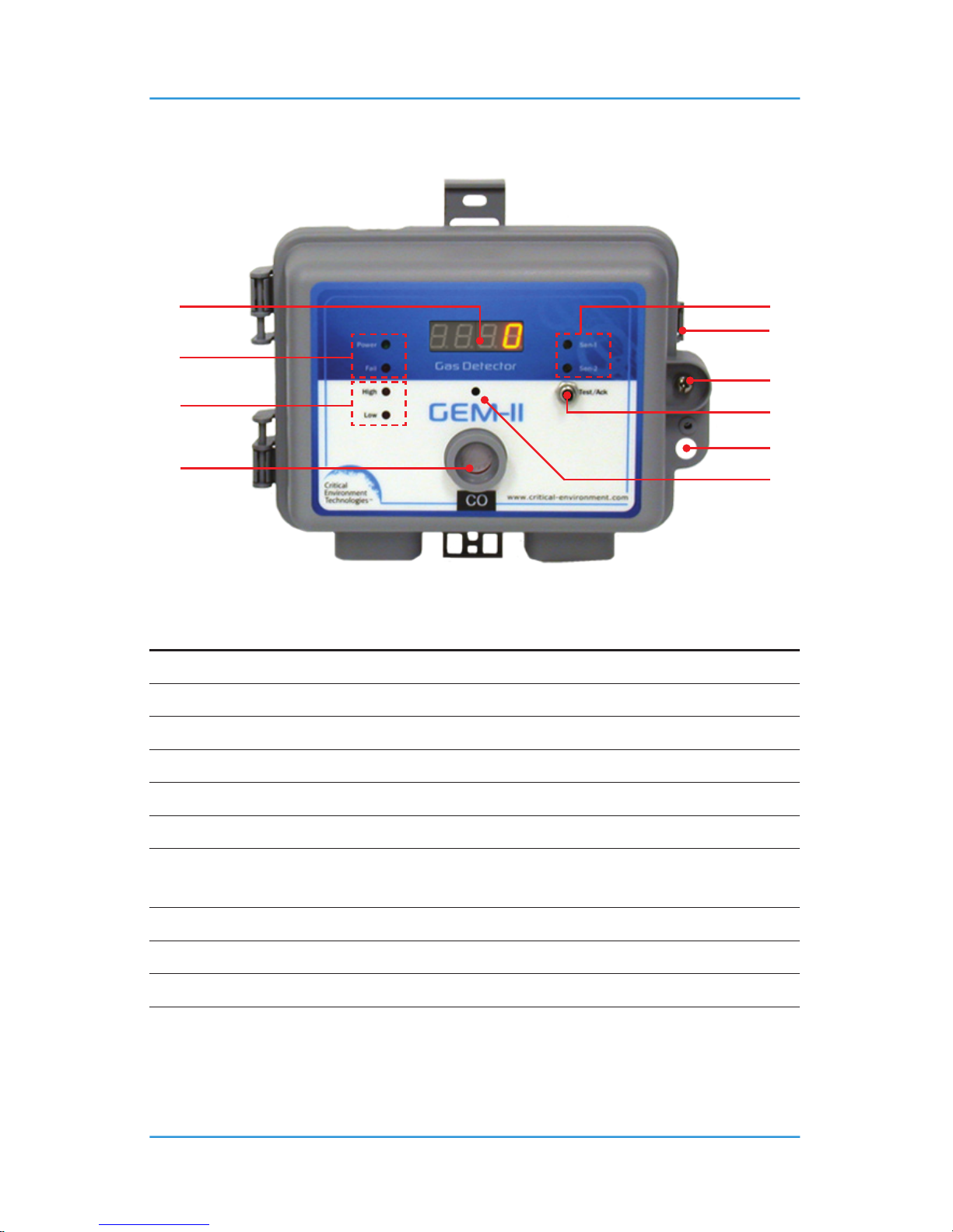
5.1 Standard Exterior Enclosure
NUMBER FEATURE FUNCTION
➊
Digital Display Optional LED digital display
➋
LED Sensor Indicators Indicates Channel 1 or Channel 2
➌
Door Latch Secures door
➍
LED Indicators Indicates Power & Fail
➎
Door Screw Secures door
➏
Gas Alarm LED Indicates High and Low alarm levels
➐
Alarm Acknowledge-Test
Push button for alarm acknowledgement &
testing
➑
Audible Alarm Internal audible alarm
➒
Sensor Opening To monitor diused air and gas
➓
Padlock Opening For padlock
Page 20
20 © 2014 All rights reserved. Data subject to change without notice.
GEM-II - Operation Manual Rev. E | 2014.10
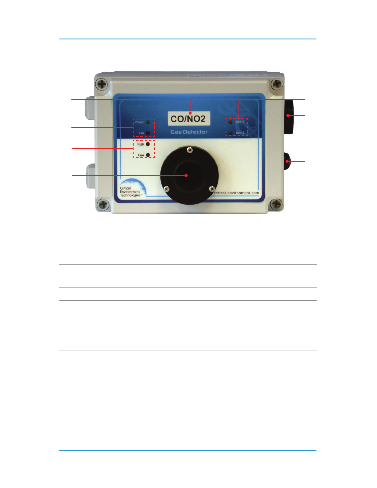
5.2 Watertight Exterior Enclosure
NUMBER FEATURE FUNCTION
➊
Digital Display Optional LED digital display
➋
LED Sensor Indicators Indicates Channel 1 or Channel 2
➌
Audible Alarm
Watertight audible alarm & silence push
button
➍
LED Indicators Indicates Power & Fail
➎
Gas Alarm LED Indicates High and Low alarm levels
➏
Silence Button Watertight silence push button
➐
Splash Guard
Optional splash guard secured with
stainless steels screws
NOTE: Audible alarm and silence push button were moved to right of enclosure to maintain
water tightness of enclosure.
Page 21
© 2014 All rights reserved. Data subject to change without notice. 21
Rev. E | 2014.10 GEM-II - Operation Manual
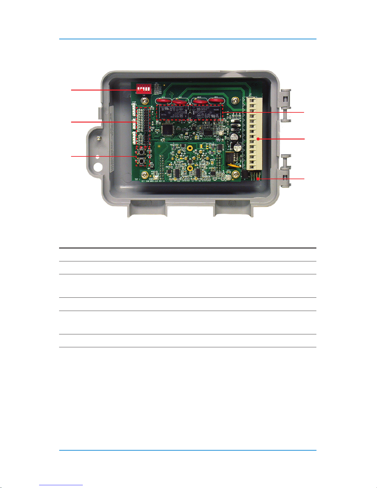
5.3 Interior System Layout
NUMBER FEATURE FUNCTION
➊
Dip Switches For access to time delays
➋
Dry Contact Relays For Low & High Alarm
➌
Jumpers
For calibrations & other service set-up
functions
➍
Wiring Terminal Pluggable wiring terminal
➎
Push Buttons
For service access & additional test
functions
➏
Half Wave / Full Wave Jumper (J2) For conguring for 24 VAC operation
Page 22
22 © 2014 All rights reserved. Data subject to change without notice.
GEM-II - Operation Manual Rev. E | 2014.10
6 INSTALLATION
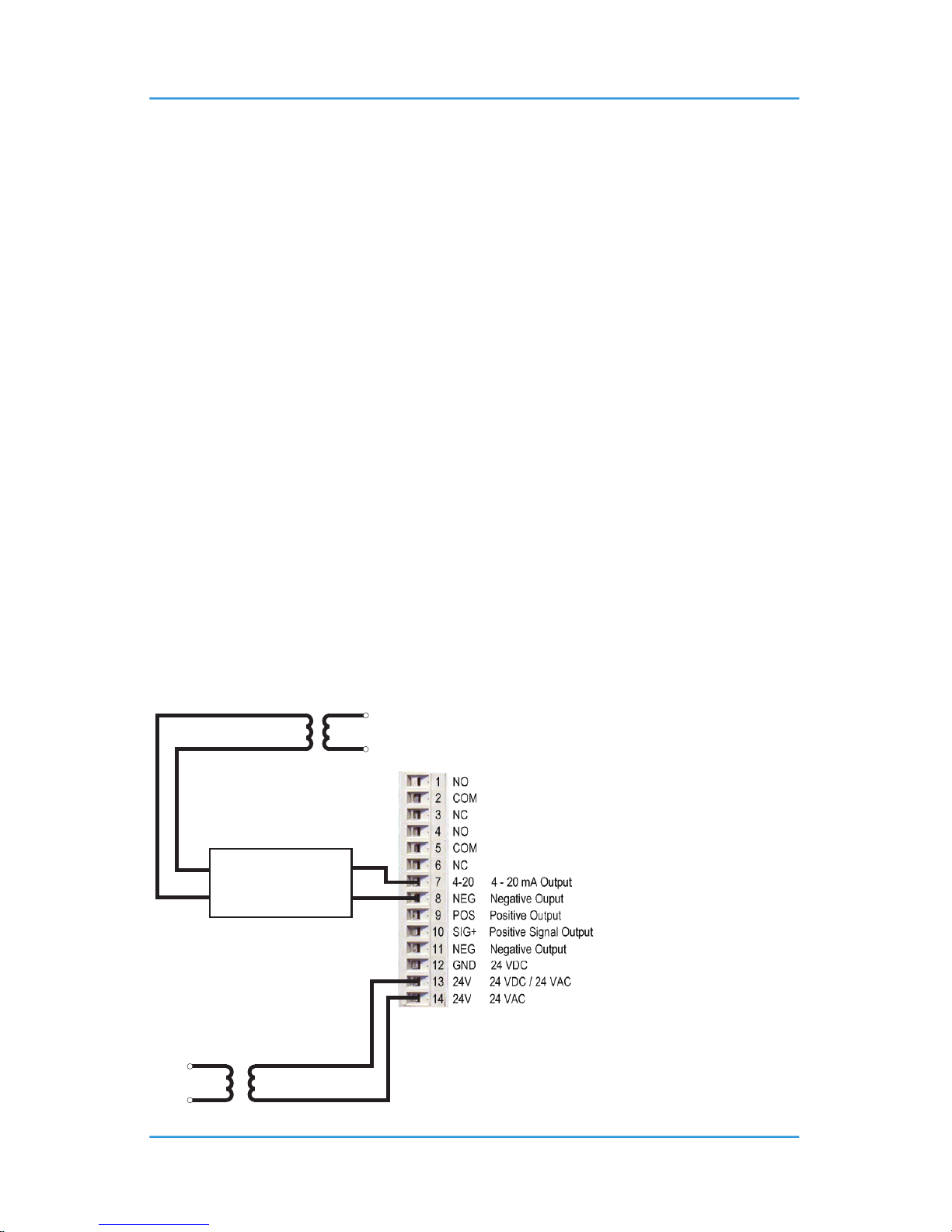
6.1 AC and DC Wiring
The GEM is a low voltage powered gas detector. All wiring should be run within properly
grounded (earth or safety) conduit. Signal output and supply should be in shielded cable.
The remote sensor wiring should be done with four conductor shielded 18 awg stranded wire in
a separate conduit from all other wiring.
THREE WIRE CONNECTION
If providing VDC or VAC Ground Referenced use terminals 12 & 13. This is now a Half Wave device
in this conguration Please observe polarity. The Ground referenced AC must be connected to
terminal 12. J2 open. Factory default.
FOUR WIRE CONNECTION
If providing VAC power, using terminals 13 & 14. This is now a Full Wave device in this
conguration, and requires a isolated supply (separate 24 VAC transformer with NO Ground
connections) and J2 be shorted.
See drawings below – if uncertain contact CETCI service for assistance.
IMPORTANT: WIRING EXAMPLES: NON GROUNDED REFERENCE SUPPLIES ONLY
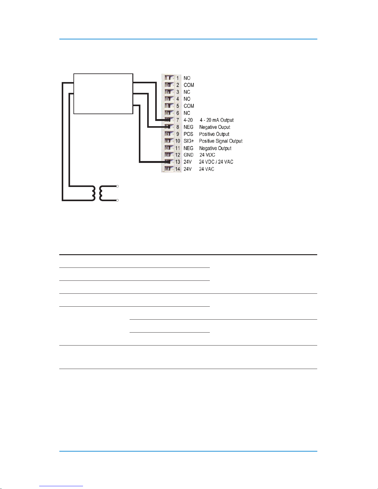
6.1.1 Wiring Example 1
Wiring Example 1
24 VAC
GND
SIGNAL
GND
120 VAC
Controller
GEM-II
24 VAC
120 VAC
24 VAC
Isolated
No Ground Reference
Page 23
© 2014 All rights reserved. Data subject to change without notice. 23
Rev. E | 2014.10 GEM-II - Operation Manual
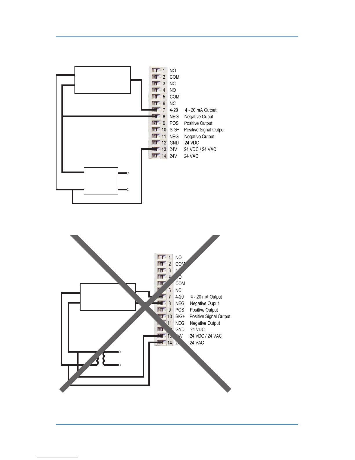
6.1.2 Wiring Example 2
Wiring Example 2
24 VDC
GND
SIGNAL
120 VAC
Controller
GEM-II
Power
Supply
6.1.3 Wiring Example 3 - INCORRECT
24 VAC
120 VAC
Wiring Example 3
INCORRECT
24 VAC
GND
SIGNAL
GND
Controller
GEM-II
Page 24
24 © 2014 All rights reserved. Data subject to change without notice.
GEM-II - Operation Manual Rev. E | 2014.10
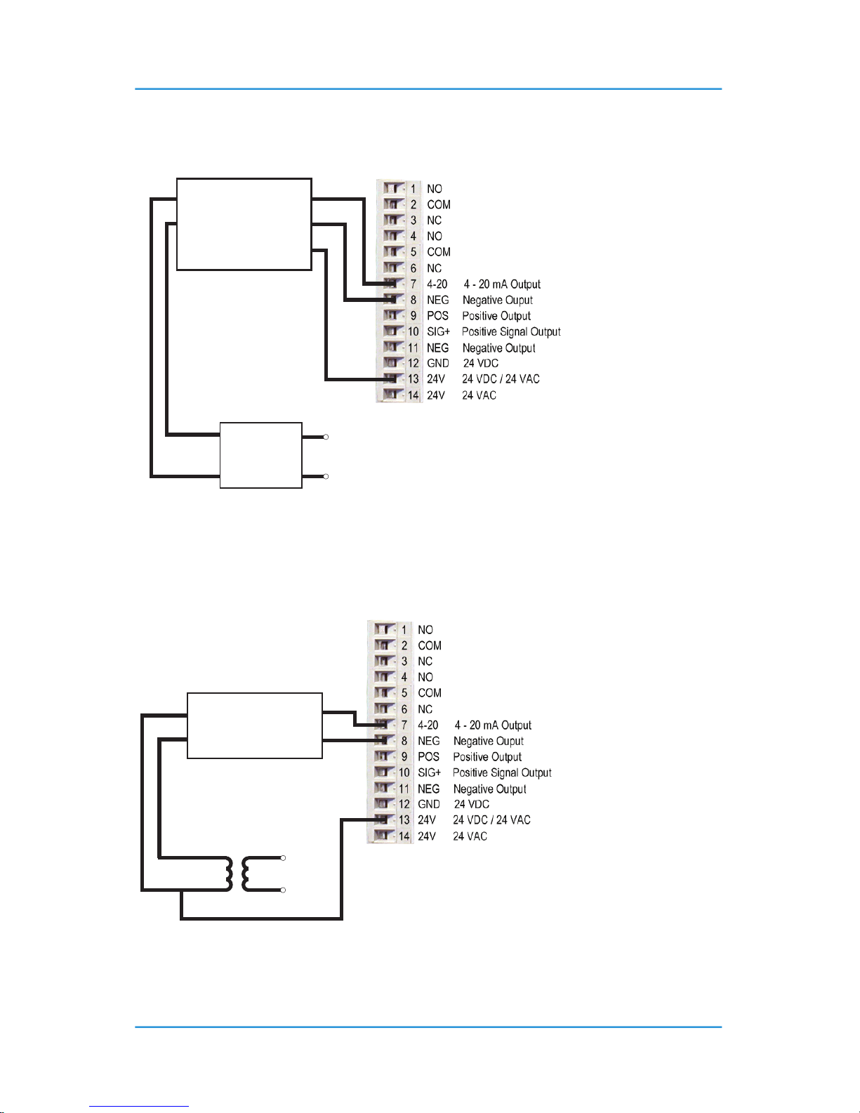
6.1.4 Wiring Example 4
Wiring Example 4
24 VDC
GND
SIGNAL
GND
24 VDC
120 VAC
Controller
GEM-II
Power
Supply
6.1.5 Wiring Example 5 (J2 Removed)
120 VAC24 VAC
Wiring Example 5
24 VAC
GND
SIGNAL
GND
Controller
GEM-II
Page 25
© 2014 All rights reserved. Data subject to change without notice. 25
Rev. E | 2014.10 GEM-II - Operation Manual
6.1.6 Wiring Example 6 (J2 Removed)
120 VAC24 VAC
Wiring Example 6
24 VAC
GND
Controller
GEM-II
Rectied
SIGNAL
GND
24 VDC
6.2 Sensor Mounting Heights
GAS APPLICATIONS / TYPES SUGGESTED MOUNTING HEIGHT
Carbon Monoxide (CO) Gas engine exhaust
4 - 6 ft from the oorNitric Oxide (NO) Diesel engine exhaust
Nitrogen Dioxide (NO
2
) Diesel engine exhaust
Sulphur Dioxide (SO
2
) All
6” from the oor
Combustibles
Propane (C
3H8
)
Methane (CH
4
)
on or near ceiling (within 12”)
Hydrogen (H
2
)
Refrigerants All
6: fromthe oor or near likely spot for
leakage
NOTE: CETCI considers 4 - 6 ft from the oor as the “Breathing Zone” when it applies to sensors
installed for vehicle exhaust applications.
Page 26
26 © 2014 All rights reserved. Data subject to change without notice.
GEM-II - Operation Manual Rev. E | 2014.10
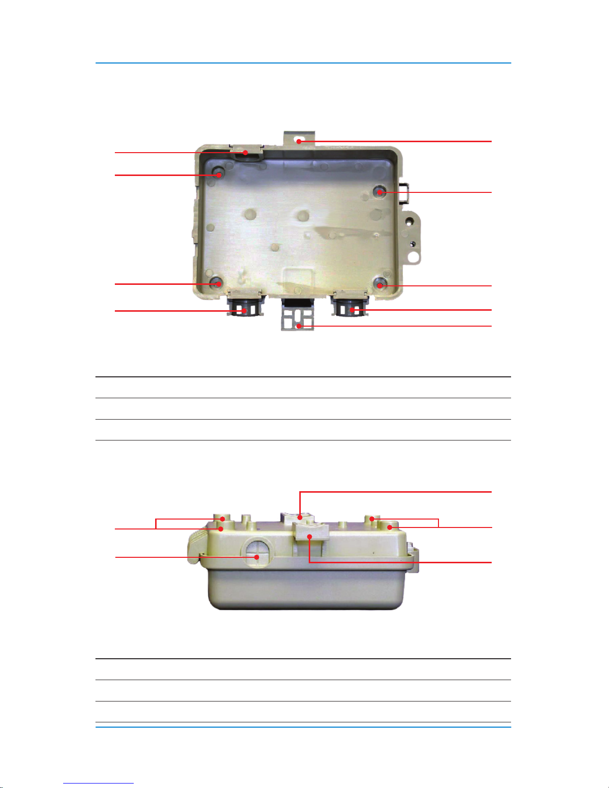
6.3 Standard Enclosure Mounting Components
6.3.1 Enclosure Base
NUMBER FEATURE
➊
Molded-in mounting bracket
➋
Conduit Entry
➌
Alternative mounting holes
6.3.2 Enclosure Top
NUMBER FEATURE
➊
Molded-in mounting bracket
➋
Conduit Entry
➌
Alternative mounting holes
Page 27
© 2014 All rights reserved. Data subject to change without notice. 27
Rev. E | 2014.10 GEM-II - Operation Manual
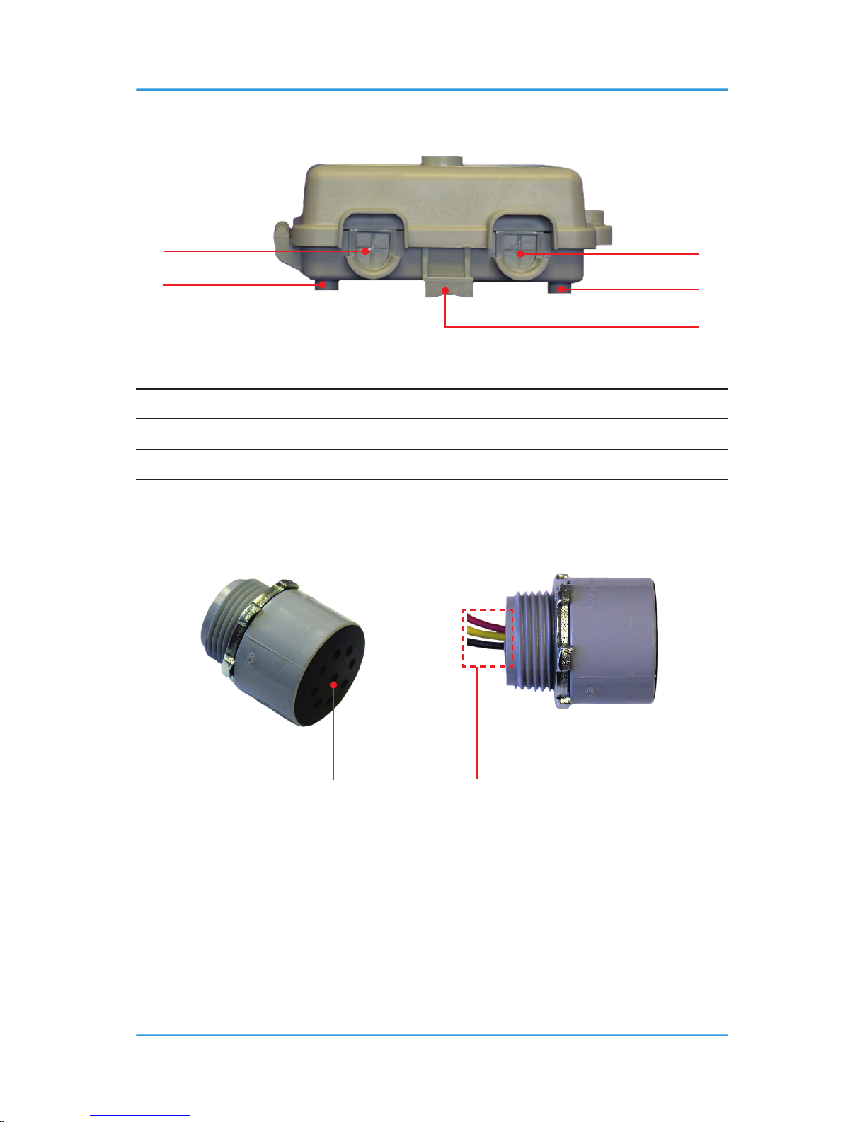
6.3.3 Enclosure Bottom
NUMBER FEATURE
➊
Molded-in mounting bracket
➋
Conduit Entry
➌
Alternative mounting holes
6.4 Remote Sensor Housing
Catalytic or solid state
sensor breathes
through these openings.
Wiring:
1. Red (+)
2. Yellow (Signal)
3. Black (-)
Page 28
28 © 2014 All rights reserved. Data subject to change without notice.
GEM-II - Operation Manual Rev. E | 2014.10
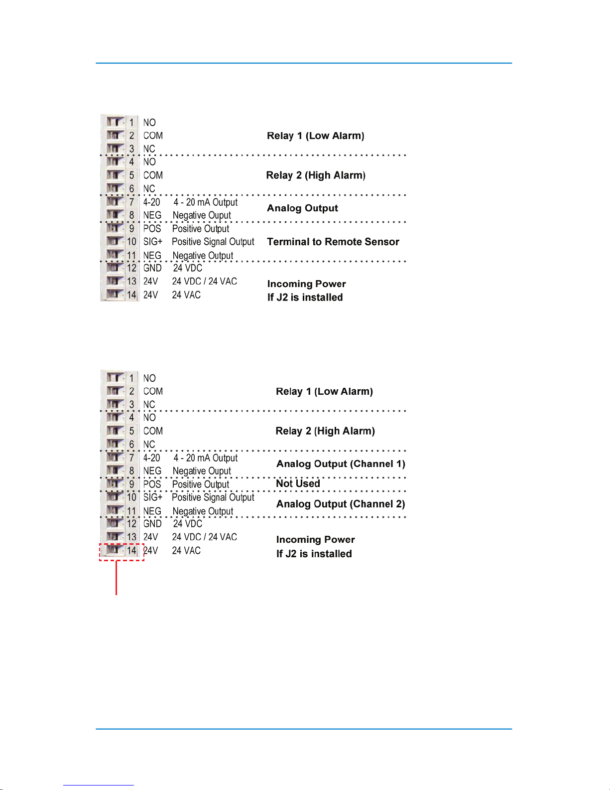
6.5 Wiring Connections
6.5.1 Types A, B and D
6.5.2 Type E
Has a sticker placed over area that says See Wiring. Remove to install J2.
Page 29

© 2014 All rights reserved. Data subject to change without notice. 29
Rev. E | 2014.10 GEM-II - Operation Manual
6.6 Important Notes for Wiring
GEM is a low voltage powered gas detector. If providing VAC power, use terminals 12 & 13. If
providing VDC power, use terminals 12 & 13 and observe polarity. Reference Section 6.5 Wiring
Connections.
Fan / alarm control wiring is terminated at terminals 1 to 6. The relays are designed to switch fan
“starters” not the fans directly. The relay contacts are rated 5 amps @ 240 VAC each, S.P.D.T.
An analog output of 4 - 20 mA is available for one or two sensors. Channel 1 sensor analog
outputs are achieved by wiring to terminals 7 & 8 and observe polarity. Channel 2 sensor analog
outputs are achieved by wiring to terminals 10 & 11.
Specic GEM types will also act as controllers to which remote transmitters can be connected.
GEM Type “B” and type “D” will accommodate one remote sensor or analog transmitter. To
connect one remote sensor or analog transmitter to a GEM, use terminals 9, 10 & 11 and observe
polarity.
6.7 System Installation
There are two exterior mounting brackets, one top and one bottom of the base of the enclosure.
Alternatively, remove the slot / Robertson head screw securing the hinged door. There are four
only 3/16” diameter corner mounting holes located inside the system enclosure base. Secure the
system to any at surface.
6.7.1 Low Voltage Power
Drill out one or more of the PVC conduit entry hole plugs located at bottom left or right or
top left edge of system enclosure base. Reference Section 6.3 Standard Enclosure Mounting
Components.
If supplying VAC operational power, pull two wires suitable for low voltage from power source to
the terminals 13 & 14 for Full Wave operation.
If supplying VDC or VAC, wire to terminals 12 & 13. J2 Removed. Factory default.
NOTE: Maximum distance between the GEM and a remote sensor should not exceed 500 ft.
Page 30

30 © 2014 All rights reserved. Data subject to change without notice.
GEM-II - Operation Manual Rev. E | 2014.10
6.7.2 Wiring to Remote Sensor
Three-conductor, 16 - 18 gauge, stranded wire is required between the control panel and the
remote solid-state sensor (reference Section 6.8 Installation Examples, Type D with Onboard &
Remote Sensors and Type E with Two Onboard Sensors). Under most local electrical codes, low
voltage wires cannot not be run within the same conduit as line voltage wires. 3-conductor, 16
- 18 gauge wire / cable must be shielded when connecting to a remote analog transmitter. The
LPT-A or LPT series remote analog transmitter enclosures have several conduit entry locations
(general purpose enclosure).
NOTE: DO NOT use solid-core wire for connection to wiring terminal strip. Any damage caused by
using solid-core wire will void warranty. Use stranded wire within conduit ONLY.
6.7.3 Voltage to Remote Sensors
The voltage supplied by the controller to remote solid state sensors should measure
approximately 5.0 VDC ± 2%, at the remote sensor. Voltage supplied by the controller to remote
analog transmitters should measure approximately 24 VDC nominal. This voltage is factory set
at time of manufacturing. If these voltages are not attained after installation, the wrong gauge
wire may have been used or the wiring run is too long.
The remote sensor housing comes with a 3/4” conduit thread and nut to allow installation in any
standard electrical junction box (to be supplied by the installer). Connect three low voltage wires
between it and the controller and observe polarity.
6.7.4 Relay Connections
System relays are dry contacts and designed to operate fan starters or coils to control equipment
that draws more than 5 amps start-up and / or operational current.
NOTES:
1. The system does not provide any power from these terminals. Dry contacts operate
like a switch to simply activate (switch on) or de-activate (switch o) equipment to be
controlled, such as fan starters.
2. System relays are S.P.D.T. (single pole, double throw) thereby providing one set of usable
dry contacts for each relay. Because the GEM series systems are designed to be fail-safe,
any equipment to be controlled by the system relays should be wired to the “NC” (Normally
closed) and “COM” (Common) terminals. The relay coils are normally energized in nonalarm state for fail-safe operation.
Page 31
© 2014 All rights reserved. Data subject to change without notice. 31
Rev. E | 2014.10 GEM-II - Operation Manual
Upon application of power, the green LED light indicator(s) will illuminate and the LED between
Sen-1 & Sen-2 will be blinking but all alarms are disabled for 2 minutes for a system warm up
period. After the warm up period, the system may exhibit gas alarm condition(s) if one or both
of the sensors has not completely stabilized during the warm up period. This is normal and the
length of time the gas alarms exist is dependent upon the length of time since the unit was last
powered up and the state of the environment it is installed in. After warm up, only the green
power LED(s) illuminate indicating normal operation and the relays are energized indicating
normal “Fail-safe” status.
6.8 Installation Examples
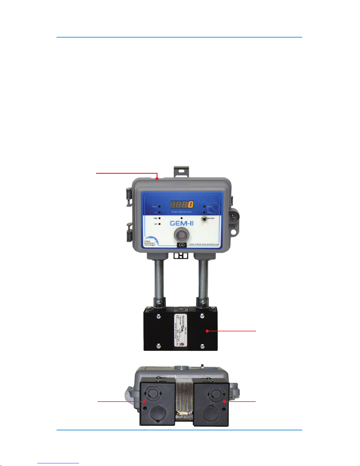
6.8.1 Type A with Internal Sensor and Enclosed Transformer
Line voltage side
of enclosed
transformer.
Line voltage side
of enclosed
transformer.
Low voltage and
line voltage are
segregated in this
transformer.
Line voltage can
enter through
the upper conduit
entry port.
GEM Type A is a
controller with
one integral
electrochemical
sensor.
Page 32
32 © 2014 All rights reserved. Data subject to change without notice.
GEM-II - Operation Manual Rev. E | 2014.10
NOTES for Type A with Enclosed Transformer:
1. Enclosed transformer shown in this photo is an optional accessory.
2. Conduit stubs shown in this photo are not supplied.
3. This photo is representative of just one way to install transformer.
4. This photo shows the optional LED digital display
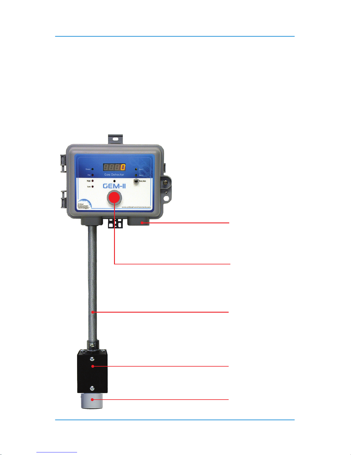
6.8.2 Type B with Remote Sensor or Analog Transmitter
Standard electrical junction
box must be supplied by
installer
Remote sensor
Conduit and 3-conductor
wire to remote sensor
supplied by installer.
Rubber plug covering what
would normally be opening
for sensor to breathe.
Installer supplied low
voltage operating power.
GEM Type B is a controller with one
remote catalytic or solid state sensor or
one remote analog transmitter.
This image shows the GEM Type B with a
remote catalytic or solid state sensor.
Mounting height 4 - 6 ft from the oor (the
“breathing zone”)
Page 33
© 2014 All rights reserved. Data subject to change without notice. 33
Rev. E | 2014.10 GEM-II - Operation Manual
NOTES for Type B with Remote Sensor or Analog Transmitter:
1. This photo shows the optional LED digital display.
2. In this installation, the remote sensor is for heavier than air gases such as propane or a solid
state refrigerant gas so the sensor should be installed 6” from the oor or near the most
likley are to leak.
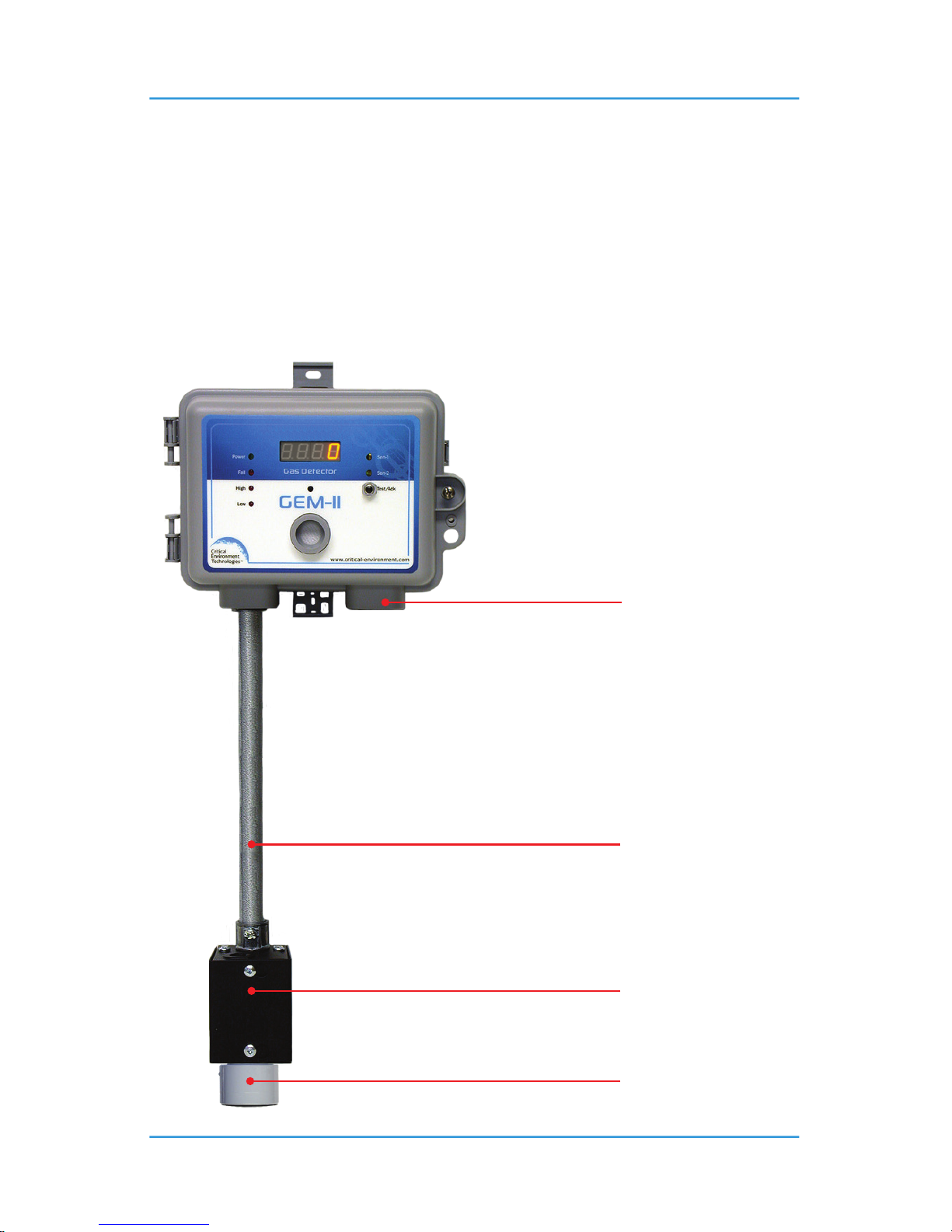
6.8.3 Type D with One Internal & One Remote Sensor
GEM Type D is a controller with one
integral electrochemical sensor and
one remote catalytic, or solid
state sensor, or one remote analog
transmitter.
Mounting height 4 - 6 ft from the oor (the
“breathing zone”)
Standard electrical junction
box must be supplied by
installer
Remote sensor
Conduit and 3-conductor
wire to remote sensor
supplied by installer.
Installer supplied low
voltage operating power.
Page 34
34 © 2014 All rights reserved. Data subject to change without notice.
GEM-II - Operation Manual Rev. E | 2014.10
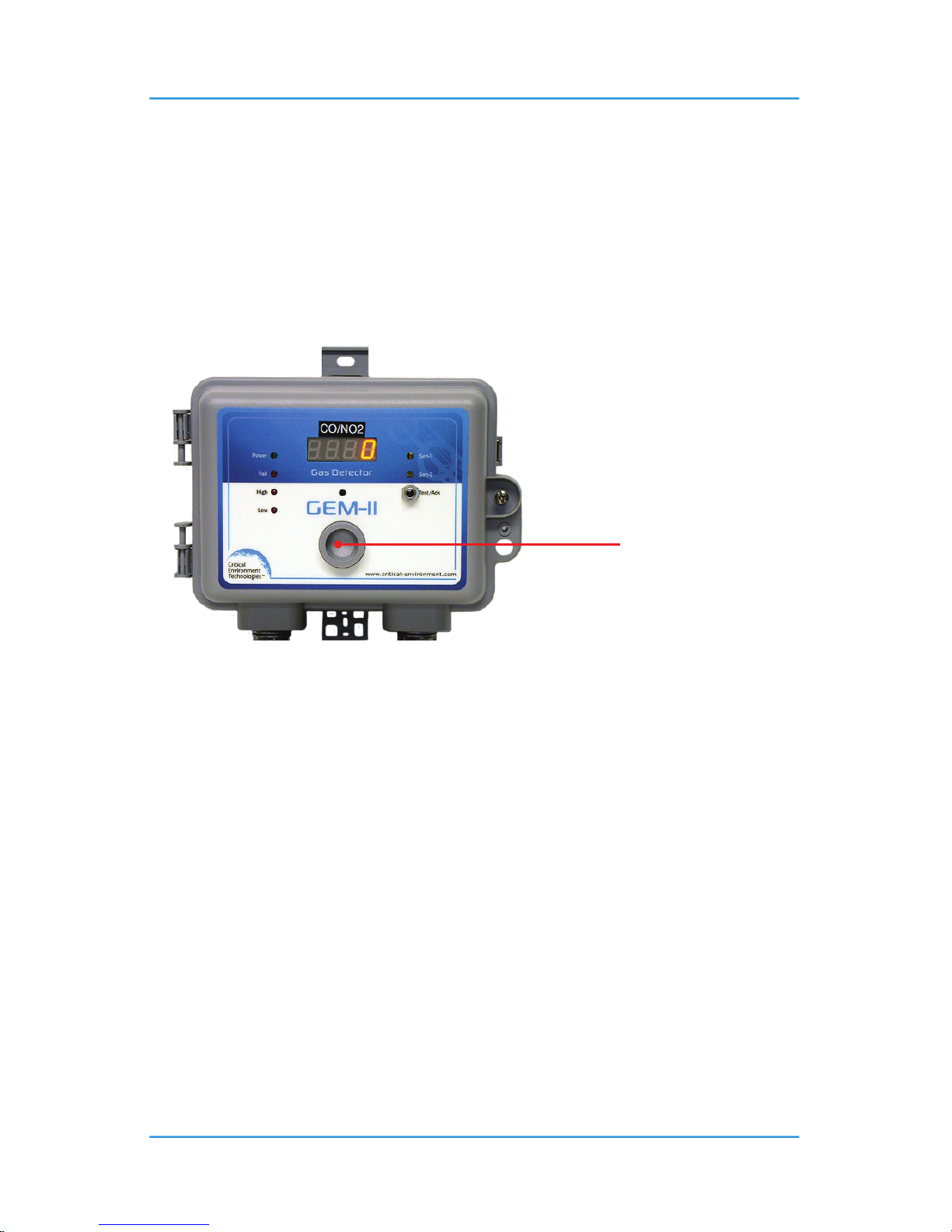
NOTES for Type D with One Internal & One Remote Sensor:
1. This photo shows the optional LED digital display.
2. In this installation, the remote sensor is for heavier than air gases such as propane or a solid
state refrigerant gas so the sensor should be installed 6” from the oor or near the most
likley are to leak.
6.8.4 Type E with Two Internal Sensors
7 OPERATION
7.1 System Operation
In the event of a burned-out, damaged or missing catalytic or solid state sensor element, the
controller will indicate fail condition on the front door by illumination of the red fail LED. At
this point, both system relays will have reversed state (de-energized) and anything connected
to them will be running continuously. Normal system operation will not occur until the fault
condition has been rectied. The same condition will occur if the 4 - 20 mA signals from the
remote LPT-A or LPT transmitter are broken or interrupted.
NOTES:
1. Fail condition overrides any system time delays that may have been set.
2. Reference photo in Section 5.1 Standard Exterior Enclosure for location of LEDs, and test-
buttons.
Two integral electrochemical sensors such as CO
(gas engine exhaust) & NO2
(diesel engine exhaust)
GEM Type E is a controller with
two integral electrochemical
sensors.
Page 35

© 2014 All rights reserved. Data subject to change without notice. 35
Rev. E | 2014.10 GEM-II - Operation Manual
In the event of a gas build up beyond the preset low alarm trip point, the CH-1-Int. LED (outer
door right side) illuminates, the “Low” alarm level LED (red - outer door left side) illuminates and
the low alarm relay de-energizes activating anything controlled by it. If a time delay “ON” has
been set (internal DIP switches), then the “Low” alarm LED will “ash” indicating the time delay
has been activated and the low alarm relay will not de-energize until the delay has timed out.
Once the low alarm relay has de-energized, it will re-energize automatically once the gas alarm
condition goes away, unless a time delay “OFF” (minimum run time - internal DIP switches) has
been programmed. The same procedure applies to CH-2 Ext. in the case of a two channel (two
sensors) system.
In the event of a gas build up beyond the preset high alarm trip point, the “CH-1” LED (outer door
right side) illuminates, the “High” alarm level LED (red - outer door left side) illuminates and
the high alarm relay de-energizes activating anything controlled by it. If a time delay “ON” has
been set (internal DIP switches), then the “High” alarm LED will “ash” indicating the time delay
has been activated and the high alarm relay will not de-energize until the delay has timed out.
Once the high alarm relay has de-energized, it will re-energize automatically once the gas alarm
condition has dispatched. The same procedure applies to the second channel in the case of a two
channel (two sensors) system.
NOTE: No minimum run time delay is provided for the high alarm relay.
7.2 Test Functions
A momentary test feature is provided to allow the user to test basic functionality of the circuit.
Press the “UP” push-button (internal) for 5-seconds, the audible alarm will beep once to
indicate it is in the 5-second test function. Release the “UP” push-button after 5-seconds and an
automatic test function will occur.
Alternatively use the silence push-button on the front door to perform the same function.
The low alarm relay will de-energize and the low alarm LED on the front door will illuminate.
The low alarm relay will then re-energize while the low alarm LED stays lit for 10-seconds.
Next, the high alarm relay will de-energize, the high alarm LED on the front door will illuminate
and the audible alarm will activate. The relay will then re-energize but the high alarm LED and
the audible alarm will stay activated for 10-seconds. After 10-seconds, everything resets to
normal operating condition.
Page 36
36 © 2014 All rights reserved. Data subject to change without notice.
GEM-II - Operation Manual Rev. E | 2014.10
If a longer test sequence is desired, hold down the “UP” push-button for 10-seconds to activate
the low alarm relay, high alarm relay, low alarm LED, and high alarm LED for 15-minutes.
To abort this test, press the internal “UP” push-button or the exterior silence push-button and
everything will reset to normal operating condition.
If the GEM is equipped with a digital display, it will indicate “test” during this test period.
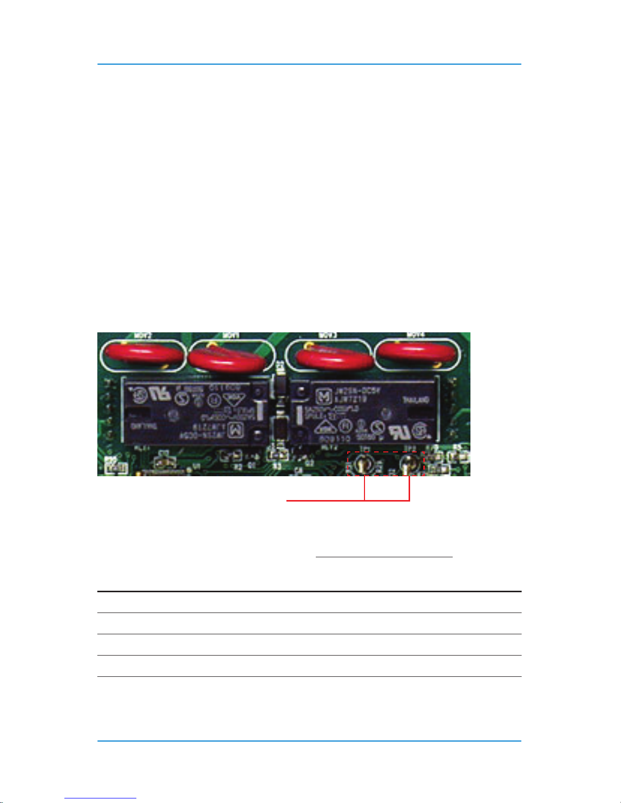
Voltage Output to Test Points “TP-1” and “TP-2”:
NOTE: The voltage output when jumper J6 is set to the resting position “1” is 4.0 VDC.
Attach the meter leads to the two test points (TP-1 & TP-2) located just below the high alarm
relay (RL V2) on the main circuit board. Set the meter to volts DC with one decimal point. The
range of 0-4.0 VDC is equal to the full measurement range of the sensor. Eg. HVAC CO sensor has
a standard measurement range of 0 - 200 ppm. Therefore 4.0 VDC = 200 ppm.
Move the Jumper J6 to position 2 when monitoring the Internal Sensor or in position 3 for the
External Sensor.
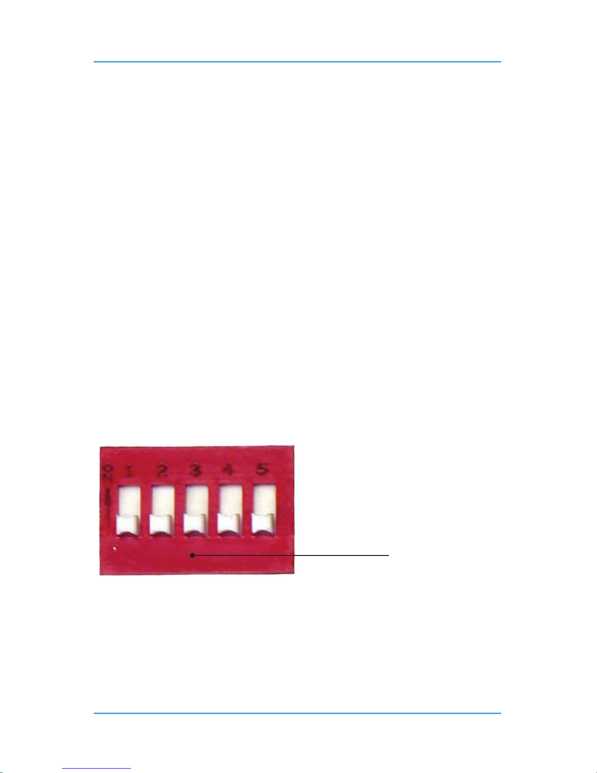
7.3 Dip Switch Package
Dip switch - position description:
• 5) Audible “on” / “o”
• 4) Audible alarm time delay “on” (5-min.)
• 3) High gas alarm time delay “on” (5-min.)
• 2) Low gas alarm time delay “o” (10-min.)
• 1) Low gas alarm time delay “on” (2-min.)
Located upper left corner of
main circuit board.
Page 37

© 2014 All rights reserved. Data subject to change without notice. 37
Rev. E | 2014.10 GEM-II - Operation Manual
NOTES:
1. Dip switches in the “up” position are “on”.
2. Time delay durations can be changed by user.
3. Fixed delay durations indicated above are factory default settings.
7.4 Internal Audible Alarm Operation
If DIP switch “5” is in the “up” position, the internal audible alarm responds to whatever
commands it is given by the microprocessor in the circuit.
If DIP switch “5” and DIP switch “4” are in the “up” position, the audible alarm responds after the
user preset time delay function for the audible alarm has timed out.
If DIP switch “5” is in the “down” position, the audible alarm does not respond at all.
The internal audible alarm normally activates with a steady tone when a “high” gas alarm
condition exists.
The internal audible alarm normally activates with a pulsing tone when a fault condition exists.
A fault condition could consist of any of the following:
• Remote catalytic or solid state sensor failure (open loop)
• Analog signal from a remote LPT-A or LPT is not registering with the GEM.
• Smart sensor board is not plugged into the main board.
NOTE: Fault conditions automatically override the ON / OFF DIP switch “5” if it has been set to
the “up” position to turn the audible alarm o.
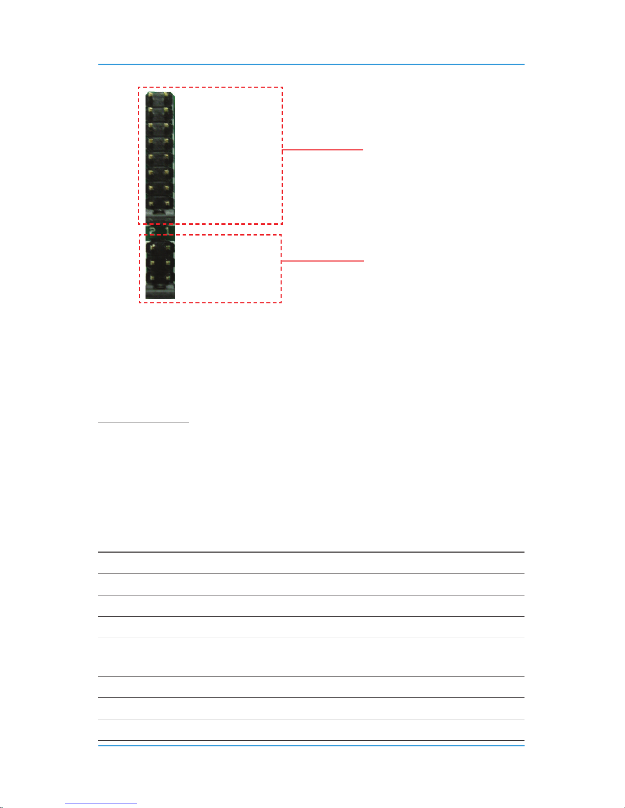
7.5 Jumpers
There are two banks of jumpers located directly below the DIP switches. One bank of nine (9)
jumpers (“J7” upper bank) and one bank of four (4) jumpers (“J6” lower bank). These jumpers
allow the user to perform a wide range of set up and calibration functions. The following table
details the jumper settings for each bank of jumpers and explains the function enabled when
these jumper positions are selected.
NOTE: Always set jumper from J6 rst followed by jumper from J7.
Page 38

38 © 2014 All rights reserved. Data subject to change without notice.
GEM-II - Operation Manual Rev. E | 2014.10
FUNCTION DESIRED
J6 LOWER
JUMPER BANK
J7 UPPER
JUMPER BANK
Resting
(Jumpers for the Upper Bank, J7 are disabled)
1 1
Setting Span Gas Value 2 (Internal Sensor) 2
Perform Zero (Null) Calibration 2 (Internal Sensor) 3
Perform Span Calibration 2 (Internal Sensor) 4
Adjust Low Gas Alarm Ascending Value 2 (Internal Sensor) 5
Adjust High Gas Alarm Ascending Value 2 (Internal Sensor) 6
Adjust Low Gas Alarm Descending Value 2 (Internal Sensor) 7
Adjust High Gas Alarm Descending Value 2 (Internal Sensor) 8
Enable / Disable Current Output 2 (Internal Sensor) 9
Setting Span Gas Value 3 (External Sensor) 2
Perform Zero (Null) Calibration 3 (External Sensor) 3
PERFORM SPAN CALIBRATION 3 (External Sensor) 4
Adjust Low Gas Alarm Ascending Value 3 (External Sensor) 5
Adjust High Gas Alarm Ascending Value 3 (External Sensor) 6
Adjust Low Gas Alarm Descending Value 3 (External Sensor) 7
Adjust High Gas Alarm Descending Value 3 (External Sensor) 8
Enable / Disable Current Output 3 (External Sensor) 9
NOTE: Jumper - 4 location on the lower jumper bank (J6) is used to set custom time delays for
relays and internal audible alarm. These functions will be explained in another section of this
manual.
Page 39
© 2014 All rights reserved. Data subject to change without notice. 39
Rev. E | 2014.10 GEM-II - Operation Manual
NOTE: In this photo, the jumper tab for both banks of jumpers is covering “J1” resting position.
7.6 Adjusting Alarm Set Points
Equipment Required: Voltmeter 1 mV resolution if using Open Door calibration or setting Alarms,
Philips screw driver if using Open Door calibration or setting Alarms.
The GEM is congurable as single or dual channel detector and as such there are two ascending
gas alarm set points and two descending gas alarm set points. Almost all installations of the
GEM will use the factory default alarm set points. Default set points are as follows:
SENSOR LOW ALARM HIGH ALARM RANGE
Carbon Monoxide (CO) 25 ppm 100 ppm 200 ppm
Nitric Oxide (NO) 35 ppm 50 ppm 100 ppm
Nitrogen Dioxide (NO
2
) 0.7 ppm 1.5 ppm 10 ppm
Sulphur Dioxide (SO
2
) 1.0 ppm 5.0 ppm 20 ppm
Propane (C
3H8
), Methane
(CH4) or Hydrogen (H2)
10% LEL 20% LEL 50% LEL
Refrigerants 500 ppm 1,000 ppm 2,000 ppm
Temperature (
o
C) 30oC 40oC 60oC
Temperature (
o
F) 75oF 90oF 100oF
J7 - 9
J7 - 8
J7 - 7
J7 - 6
J7 - 5
J7 - 4
J7 - 3
J7 - 2
J7 - 1 (Resting)
J6 - 4
J6 - 3
J6 - 2
J6 - (Resting)
Upper bank jumpers set (J7). This bank
of jumpers allows specic functions
for internal and external sensors. The
target sensor is set using the lower
bank of jumpers.
Lower bank jumper set (J6). This
bank of jumpers allows set up and
conguration for both internal and
external sensors.
Page 40
40 © 2014 All rights reserved. Data subject to change without notice.
GEM-II - Operation Manual Rev. E | 2014.10
Reference table in Section 7.5 Jumpers. If the GEM has been equipped with an LED digital
display, set values according to what is displayed. If the GEM has been supplied without a digital
display, you will require a digital multi-meter.
Attach the meter leads to the two test points (TP-1 & TP-2) located just below the high alarm
relay (RL V2) on the main circuit board (reference photo below). Set the meter to volts DC with
one decimal point. Time delays are set using a voltage reference of 0-4 VDC. Reference the tables
in Section 7.7 Time Delays for Relay Operations.
Move the jumper on the lower jumper bank J6 from its resting position (P-1) and place it on
the appropriate jumper position as indicated in the table below top achieve the desired alarm
setting. Use the “UP” or “DOWN” push-buttons to set the desired alarm value. Once all alarm
settings have been set to desired values, move the jumper back to its resting position on the
lower jumper bank J6. All new values will be written to the EEPROM.
Test Points: TP-1 & TP-2
FUNCTION DESIRED
J6 LOWER JUMPER BANK J7 UPPER
JUMPER
BANK
Int Ext
SET LOW ASCENDING ALARM VALUE P2 P3 P5
SET HIGH ASCENDING ALARM VALUE P2 P3 P6
SET LOW DESCENDING ALARM VALUE P2 P3 P7
SET HIGH DESCENDING ALARM VALUE P2 P3 P8
Page 41

© 2014 All rights reserved. Data subject to change without notice. 41
Rev. E | 2014.10 GEM-II - Operation Manual
Alarm settings for GEM detectors are voltage settings. The range of 0 - 4.0 VDC is equal to the
full measurement range of the sensor. E.g. HVAC CO sensor has a standard measurement range
of 0-200 ppm. Therefore, 4.0 VDC = 200 ppm. Reference the formula below and the table in
Section 7.5 Jumpers.
DESIRED SET POINT / SENSOR RANGE = % OF RANGE
e.g. 100 ppm / 200 ppm = 50% of range
50% OF 4.0 VDC = 2.0 VDC.
Therefore the required voltage setting to achieve an alarm set point of 100 ppm is 2.0 VDC.
7.6.1 Voltage Reference Table for Alarm Settings
SENSOR / GAS MEASUREMENT RANGE
LOW ALARM
SET VOLTAGE
HIGH ALARM
SET VOLTAGE
CO 0 - 200 ppm 25 ppm / 0.50 VDC 100 ppm / 2.00 VDC
CO 0 - 200 ppm 35 ppm / 0.70 VDC 200 ppm / 4.00 VDC
NO
2
0 - 10 ppm 0.7 ppm / 0.28 VDC 1.0 ppm / 0.40 VDC
NO
2
0 - 10 ppm 2.0 ppm / 0.8 VDC 5.0 ppm / 2.00 VDC
O
2
0 - 25.0% Volume 19.5% Vol. / 3.12 VDC 23.0% Vole. / 3.68 VDC
O
2
0 - 25.0% Volume 17.0% Vol. / 2.72 VDC 18.5% Vol. / 2.96 VDC
O
3
0 - 2.00 ppm 0.10 ppm / 0.20 VDC 0.30 ppm / 0.60 VDC
O
3
0 - 2.00 ppm 0.30 ppm / 0.60 VDC 1.00 ppm / 2.00 VDC
NO 0 - 100 ppm 25 ppm / 1.00 VDC 50 ppm / 2.00 VDC
H
2
S 0 - 50 ppm 10 ppm / 0.80 VDC 15 ppm / 1.20 VDC
SO
2
0 - 20 ppm 2 ppm / 0.40 VDC 5 ppm / 1.00 VDC
H
2
0 - 4,000 ppm 1000 ppm / 1.00 VDC 2000 ppm / 2.00 VDC
C
3H8
0 - 50% LEL 10% LEL / 0.80 VDC 20% LEL / 1.60 VDC
C
3H8
0 - 50% LEL 20% LEL / 1.60 VDC 40% LEL / 3.20 VDC
CH
4
0 - 50% LEL 10% LEL / 0.80 VDC 20% LEL / 1.60 VDC
CH
4
0 - 50% LEL 20% LEL / 1.60 VDC 40% LEL / 3.20 VDC
H
2
0 - 50% LEL 10% LEL / 0.80 VDC 20% LEL / 1.60 VDC
Freons
(R series)
0-2000 ppm 500 ppm / 1.00 VDC 1000 ppm / 2.00 VDC
Page 42

42 © 2014 All rights reserved. Data subject to change without notice.
GEM-II - Operation Manual Rev. E | 2014.10
7.7 Time Delays for Relay Operations
GEM oers a wide range of time delay settings that are user congurable. If the GEM has been
equipped with the LED digital display option, read the values on the display as you change them
to suit your application. If the GEM does not have a digital display, you will require a digital volt
meter set to volts DC, one decimal point. The following tables are a guideline to follow to achieve
desired time delays. Voltage reference is 0 - 4 VDC.
VOLT READING AT TEST POINTS TIME DELAY IN MINUTES
0 N/A
0.02 0.1
0.04 0.2
0.06 0.3
0.08 0.4
0.10 0.5
0.12 0.6
0.14 0.7
0.16 0.8
0.18 0.9
0.20 1.0
0.22 1.1
0.24 1.2
0.26 1.3
0.28 1.4
0.30 1.5
0.32 1.6
0.34 1.7
0.36 1.8
0.38 1.9
0.40 2.0
0.42 2.1
Page 43

© 2014 All rights reserved. Data subject to change without notice. 43
Rev. E | 2014.10 GEM-II - Operation Manual
VOLT READING AT TEST POINTS cont’ TIME DELAY IN MINUTES cont’
0.44 2.2
0.46 2.3
0.48 2.4
0.50 2.5
0.52 2.6
0.54 2.7
0.56 2.8
0.58 2.9
0.60 3.0
0.62 3.1
0.64 3.2
0.66 3.3
0.68 3.4
0.70 3.5
0.72 3.6
0.74 3.7
0.76 3.8
0.78 3.9
0.80 4.0
- -
1.0 5.0
1.2 6.0
1.4 7.0
1.6 8.0
1.8 9.0
2.0 10.0
2.2 11.0
2.4 12.0
Page 44

44 © 2014 All rights reserved. Data subject to change without notice.
GEM-II - Operation Manual Rev. E | 2014.10
VOLT READING AT TEST POINTS cont’ TIME DELAY IN MINUTES cont’
2.6 13.0
2.8 14.0
3.0 15.0
3.2 16.0
3.4 17.0
3.6 18.0
3.8 19.0
4.0 20.0
7.7.1 Procedure for Setting Time Delays
Move jumper from resting position (position-1) on lower bank jumper set (J6) to position-4. This
is the system conguration position. Next, select the jumper position on upper bank jumper set
(J7) to achieve the desired function. Reference photo in Section 7.5 Jumpers. Reference the table
below for appropriate jumper position locations.
Once the desired jumper position has been achieved, use the “UP” or “DOWN” push-buttons
to make changes. Changes can be viewed on the LED digital display if the GEM is equipped
with one. If the GEM is not equipped with a digital display, connect a digital multi-meter to
test points “TP-1” and “TP-2” and use the voltage tables in Section 7.7 Time Delays for Relay
Operations.
Once desired time delays have been set, move jumper back to resting position (P1) of upper
jumper bank J7. If additional time delays are desired, move the jumper to the appropriate
position and once again use the push-buttons to set desired voltage to achieve desired time
delay.
Once all desired time delay settings have been achieved, move jumper back to position-1 on
upper jumper bank J7 and move jumper back to position-1 on lower jumper bank J6. At that
point, all new settings will be written to the EEPROM.
Page 45

© 2014 All rights reserved. Data subject to change without notice. 45
Rev. E | 2014.10 GEM-II - Operation Manual
FUNCTION UPPER JUMPER BANK “J7”
Low alarm “ON” time delay P2
Low alarm “OFF” time delay P3
High alarm “ON” time delay P4
Audible alarm “ON time delay P5
7.8 Temperature Display - Unit of Measure
The GEM systems all have an “on board” temperature chip from which information is used to
temperature compensate certain sensors. This temperature chip can also be used as a second
sensor in applications where the user requires both a gas measurement and a temperature
measurement. To switch between Celsius and Fahrenheit displayed values, follow this procedure.
Move jumper from resting position (position-1) on lower bank jumper set (J6) to position-4 and
jumper on J7 to position-8. Now pressing the “UP” push-button will display the temperature
in Celsius and the output to test points “TP-1” and “TP-2” is 4.0 V. If the “DOWN” push-button is
pressed, the temperature is displayed in Fahrenheit and the output to the test points is 0 V.
Once the desired unit of measure has been achieved, move jumper back to position-1 on upper
jumper bank J6. At that point, all new settings will be written to the EEPROM.
NOTE: Temperature sensor is always considered channel-2 (external).
7.9 Latching Relay Functions
The GEM relays can be congured as “latching” for some applications.
To achieve this, move the jumper from resting position (position-1) on lower bank jumper set
(J6) to position-4. This is the system conguration position. Next, select the jumper position-9
on upper bank jumper set (J7).
Pressing the “UP” push-button activates the “latching” function and output to test points “TP-1”
and “TP-2” is 4 V. Pressing the “DOWN” push-button de-activates the latching function and the
output to test points “TP-1” and “TP-2” is 0 V.
Page 46

46 © 2014 All rights reserved. Data subject to change without notice.
GEM-II - Operation Manual Rev. E | 2014.10
Once the desired latching or non-latching function has been achieved, move jumper back to
position-1 on upper jumper bank J7 and move jumper back to position-1 on lower jumper bank
J6. At that point, all new settings will be written to the EEPROM.
7.10 LED Digital Display
The GEM system allows for a certain amount of customization of the LED digital display:
• The display can be switched completely o.
• The display brightness level can be adjusted to low or high for best visibility in your
application.
• The display can indicate the gas type only with no numerical value for some applications.
FUNCTION JUMPER SETTING
Switch digital display “ON” Jumper “J3” bridge P2 & P3
Switch digital display “OFF” Jumper “J3” bridge P1 & P2
Low brightness level for display Jumper “J4” bridge P1 & P2
High brightness level for display Jumper “J4” bridge P2 & P3
Display only gas name (acronym) Jumper “J5” bridge P1 & P2
Display gas values as well as gas name Jumper “J5” bridge P2 & P3
NOTES:
1. The default setting for detectors leaving the CETCI factory with an LED digital display are:
I. Display is “ON”
II. Brightness level is “Low”
III. Display indicates gas type and gas value.
2. The typical operation of the LED digital display is: Gas name is shown for 1-second then gas
value is shown for 2-seconds. The sequence is the same for 1 or 2-channel systems.
Page 47

© 2014 All rights reserved. Data subject to change without notice. 47
Rev. E | 2014.10 GEM-II - Operation Manual
8 CALIBRATION
8.1 Calibration Specications
8.1.1 Gas
Calibration span gases should be at least ± 5% accuracy and have a current date stamp. Gas
generators should have a current dated cell installed. Service personnel should ow zero
emissions air or 20.9% volume Oxygen (O2) before attempting to null adjust toxic gas sensors. In
some cases Nitrogen (N2) can be substituted for zero air. Contact CETCI for clarication. Nitrogen
(N2) is required to null (zero) Oxygen (O2) and Carbon Dioxide (CO2) sensors.
If an inappropriate concentration of span gas is applied during calibration, calibration may
succeed but it does not mean the equipment has been calibrated properly. CETCI is not
responsible for improperly calibrated transmitters. Follow manual instructions carefully.
8.1.2 Exception
Flow Nitrogen (N2) over Oxygen (O2) sensors before attempting to null adjust them. If the service
person is condent of air quality and is careful (do not exhale in the direction of the Oxygen
sensor being serviced while span adjusting). Oxygen in the breathing environment can be used
as a fairly accurate source of span gas (20.9% volume) “in a pinch”. It is not recommended to use
this procedure for all span adjustments of Oxygen sensors.
8.1.3 Regulators & Flow
Calibration gases that are lighter than or the same weight as air (CO, O2, etc.) should be owed at
0.5 LPM. Gases heavier than air (NO2, Cl2, etc.) should be owed between 0.5 and 1.0 LPM. Fixed
ow regulators provide more accuracy. Gases should be owed over the sensor for at least 2.5 - 4
minutes. Carbon Monoxide sensors settle out very quickly, but sensors for reactive gases (NH3,
etc.) will take longer to stabilize to the calibration gas. All cylinder regulators supplied by CETCI
use a xed ow orice.
8.1.4 Adapters
The proper calibration adapter should be utilized to allow the gas to properly diuse around the
sensor. They are available from CETCI. A humidication chamber is recommended to be utilized
for all catalytic and solid state sensors except Ammonia. This is also available from CETCI.
Page 48

48 © 2014 All rights reserved. Data subject to change without notice.
GEM-II - Operation Manual Rev. E | 2014.10
8.2 Calibrating Sensors
8.2.1 Calibration Frequency
• Parking garage detectors: Once every 12 months
• OHS applications: Once every 6 months (OHS: Occupational Health & Safety)
• Sensor targeting gases with very low TLVs: Chlorine (Cl2), Ozone (O3), etc.
Ethylene Oxide (C2H4O), etc.: Once every 6 months.
Gas Testing Frequency/Bump Testing: For the purposes of safety in OHS applications, sensors
should be gas tested once every month to conrm response.
NOTE: A calibration label should be applied after every calibration to conrm work performed
and the date it was conrmed. If a controller is involved, the alarm set points should be indicated
on a label on the front door of the enclosure so anyone working in the environment can be
aware.
Calibration is achieved at the GEM controller if the sensor is integral. If the sensor is remote
(LPT-A or LPT series analog transmitter) the calibration is achieved at the transmitter using the
procedure indicated in the operation manual provided with it.
Required Equipment: Digital multi-meter, Calibration kit, Calibration gases
Users can order the calibration kit, calibration accessories and/or gases from any CETCI
authorized distributor or they can supply their own gas and equipment as long as the gas meets
the minimum specications.
8.3 Calibration Procedure
The calibration procedure within the second generation GEM controller is jumper automated
(there are no potentiometers to adjust). To achieve calibration the user must rst tell the GEM
what concentration of span he is going to ow over the sensor. Within the controller, calibration
is a voltage setting. The range of 0-4.0 VDC is equal to the full measurement range of the sensor.
Eg. HVAC CO sensor has a standard measurement range of 0 - 200 ppm. Therefore 4.0 VDC = 200
ppm. Prior to attempting to calibrate, determine or calculate the voltage value required. Consult
the 7.6.1 Voltage Reference Table for Alarm Settings in Section 7.6 Adjusting Alarm Set Points for
standard voltages. If the value desired is not indicted, use the following formula to calculate the
voltage required:
Page 49

© 2014 All rights reserved. Data subject to change without notice. 49
Rev. E | 2014.10 GEM-II - Operation Manual
CALIBRATION SPAN GAS VALUE / 50% OF RANGE SENSOR RANGE
= % OF RANGE
e.g. 100 ppm / 200 ppm = 50% of 4.0 VDC = 2.0 VDC
Therefore the required voltage setting to calibrate with 100 ppm is 2.0 VDC.
NOTE: When calibrating solid-state sensors for combustibles or refrigerants, the span gas
must be humidied. The use of a CETCI humidication chamber is required. The humidication
chamber sits in line between the cylinder of span gas and the calibration adapter. Remove the
sponge inside the chamber and wet it under the tap. Squeeze out the excess water so it is not
dripping wet and place it back inside the chamber. As gas ows over through the chamber, it
absorbs water which acts to humidify it and the humidied span gas ows over the sensor.
8.4 Calibrating the Internal Sensor
8.4.1 Setting Span Gas Value (internal sensor)
Step 1:
Move jumper on J6 to position-2 and move jumper on J7 to position-2. The audible alarm beeps
once for conrmation. The system is now waiting for the user to set the desired value.
Step 2:
Attach digital multi-meter leads to test points TP-1 and TP-2.
Step 3:
Using the UP or DOWN push-buttons, achieve the calculated voltage on the digital multi-meter.
Reference Section 8.3 Calibration Procedure.
Step 4:
Move jumpers from J6 & J7 back to their respective resting positions.
8.4.2 Calibrating the Null (Zero) Value (internal sensor)
Step 1:
Attach regulator to cylinder of zero air, insert calibration adapter into the sensor opening in the
front of the enclosure door, and open regulator valve fully allowing zero air to ow over sensor.
Use a slight twisting motion as you gently push the calibration adapter into the sensor opening.
If the calibration adapter is hard to insert, moisten the O-ring seal slightly then try re-inserting
it.
Page 50

50 © 2014 All rights reserved. Data subject to change without notice.
GEM-II - Operation Manual Rev. E | 2014.10
Step 2:
Move jumper on J6 to position-2 and move jumper on J7 to position-3. The audible alarm
beeps once for conrmation. The system is now starting the zero calibration stabilization time
(30-seconds).
Step 3:
Attach digital multi-meter leads to test points TP-1 and TP-2. Reference Section 8 Calibration.
The voltage should be 0.0 VDC. If the audible sounds with repetitive beeps, see Section 8.8
Forcing Calibration. The audible will beep twice when the calibration begins. Leave the zero air
owing over the sensor until the GEM audible beeps three times indicating the procedure is
nished (1-minute).
Step 4:
Move jumpers from J6 & J7 back to their respective resting positions and remove the zero air or
Nitrogen.
8.4.3 Calibrating the Span Gas (internal sensor)
Step 1:
Attach regulator to cylinder of span gas.
Step 2:
Insert the calibration adapter into the sensor opening in the front of the enclosure door. Open
regulator valve fully and allow span gas to ow over sensor.
Step 3:
Move the jumper on J6 to position-2 and move jumper on J7 to position-4. The audible alarm
“beeps” once for conrmation. The system is now starting the span calibration stabilization time
(30 seconds).
Step 4:
Attach digital multi-meter leads to test points TP-1 and TP-2. Monitor the voltage. It should start
moving towards the voltage calculated for the span gas value (reference Section 8.3 Calibration
Procedure).
If the audible sounds with repetitive beeps, see Section 8.8 Forcing Calibration.
The audible will beep twice when the calibration begins. Leave the span gas owing over the
sensor until the GEM audible beeps three times indicating the procedure is nished (2-minutes).
Page 51

© 2014 All rights reserved. Data subject to change without notice. 51
Rev. E | 2014.10 GEM-II - Operation Manual
Step 5:
Move jumpers from J6 & J7 back to their respective resting positions and remove the span gas.
8.5 Calibrating Second Internal Sensor
Calibration of the second internal sensor has only one dierence from the rst internal sensor
calibration. Move the jumper from J6 to position-3 then follow the same procedure as outlined
in Section 8.4.1 to 8.4.3 using J6 position-3.
8.6 Calibrating Remote Catalytic or Solid State Sensor
8.6.1 Setting Span Gas Value (remote catalytic or SS sensor)
Step 1:
Move jumper on J6 to position-3 and move jumper on J7 to position-2. Audible alarm beeps
once for conrmation. The system is now waiting for the user to set the desired value.
Step 2:
Attach digital multi-meter leads to test points TP-1 and TP-2. Reference Section 8 Calibration.
Step 3:
Using the UP or DOWN push-buttons, achieve the calculated voltage on the digital multi-meter.
Reference Section 8.3 Calibration Procedure.
Step 4:
Move jumpers from J6 & J7 back to their respective resting positions.
8.6.2 Calibrating the Null (Zero) Value (remote catalytic or SS sensor)
Step 1:
Attach regulator to cylinder of zero air, attach ow adapter and open regulator valve fully
allowing zero air to ow over sensor. Use a slight twisting motion as you gently push the
calibration adapter into the sensor opening. If the calibration adapter is hard to insert, moisten
the O-ring seal slightly then try re-inserting it.
Page 52

52 © 2014 All rights reserved. Data subject to change without notice.
GEM-II - Operation Manual Rev. E | 2014.10
Step 2:
Move jumper on J6 to position-3 and move jumper on J7 to position-3. The audible alarm beeps
once for conrmation. The system is now starting the zero calibration stabilization time (30
seconds).
Step 3:
The audible will beep twice when the calibration begins. Leave the zero air owing over the
sensor until the GEM audible beeps three times indicating the procedure is nished (1 minute).
Step 4:
Move jumpers from J6 & J7 back to their respective resting positions and remove the zero air or
Nitrogen.
8.6.3 Calibrating the Span Gas (remote catalytic or SS sensor)
Step 1:
Attach regulator to cylinder of span gas.
Step 2:
Attach ow adapter and open regulator valve fully (xed ow regulators only) allowing span gas
to ow over sensor.
Step 3:
Move the jumper on J6 to position-3 and move jumper on J7 to position-4. The audible alarm
“beeps” once for conrmation. The system is now starting the span calibration stabilization time
(30 seconds).
Step 4:
The audible will beep twice when the calibration begins. Leave the span gas owing over the
sensor until the GEM audible beeps three times indicating the procedure is nished (2 minutes).
Move jumpers from J6 & J7 back to their respective resting positions and remove the span gas.
Page 53

© 2014 All rights reserved. Data subject to change without notice. 53
Rev. E | 2014.10 GEM-II - Operation Manual
8.7 Calibrating 4-20 mA for Incoming Analog Transmitter
NOTE: The GEM is congured at the factory and should not require this type of calibration unless
it is not functioning properly. Specialized equipment is required; only perform these functions
after consulting the factory. This NOTE applies to Sections 8.7.1 through 8.7.4.
To perform this function, you will require either an accurate current source able to generate a 4.0
mA and 12.0 mA current signal or a CETCI analog transmitter that can supply the correct current
values.
8.7.1 Using a Current Source to Calibrate the Null
Step 1:
Connect current source to pin 10 and ground to pin-11. For zero calibration, set the current
source to 4.0 mA. Move the jumper on J6 to position-3 and the jumper on J7 to position-3.
The audible will beep once for conrmation. The system is now starting the zero calibration
stabilization time (30 seconds).
Step 2:
Attach digital multi-meter leads to test points TP-1 and TP-2. Monitor the voltage. If the audible
sounds with repetitive beeps, see Section 8.8 Forcing Calibration. The audible will beep twice
when the calibration begins. The audible beeps three times indicating the procedure is nished
(2 minutes).
Step 3:
Move jumpers from J6 & J7 back to their respective resting positions.
8.7.2 Using a Current Source to Calibrate the Span
Step 1:
Connect current source to pin 10 and ground to pin-11. For span calibration set the current
source to 20.0 mA. Move the jumper on J6 to position-3 and the jumper on J7 to position-4.
The audible will beep once for conrmation. The system is now starting the span calibration
stabilization time (30 seconds).
Step 2:
Attach digital multi-meter leads to test points TP-1 and TP-2. Monitor the voltage. If the audible
sounds with repetitive beeps. Reference Section 8.8 Forcing Calibration. The audible will beep
Page 54

54 © 2014 All rights reserved. Data subject to change without notice.
GEM-II - Operation Manual Rev. E | 2014.10
twice when the calibration begins. The audible beeps three times indicating the procedure is
nished (2 minutes).
Step 3:
Move jumpers from J6 & J7 back to their respective resting positions and remove the current
source.
8.7.3 Using a CETCI Analog Transmitter to Calibrate the Null
Step 1:
At the transmitter:
For zero calibration on the transmitter, move the jumper to position-2 and set the
voltage at TP-1 and TP-2 for “0” volts DC. If transmitter has been calibrated, TP-1 and
TP-2 should be reading “0” volts DC.
At the GEM:
Move the jumper from J6 to position-3 and the jumper from J7 to position-3 The
audible will beep once for conrmation. The system is now starting the zero
calibration stabilization time (30 seconds).
Step 2:
Attach digital multi-meter leads to test points TP-1 and TP-2. Monitor the voltage. It should start
moving towards zero gas value “0”. Reference Section 8.3 Calibration Procedure. If the audible
sounds with repetitive beeps. Reference Section 8.8 Forcing Calibration. The audible will beep
twice when the calibration begins. The audible beeps three times indicating the procedure is
nished (2 minutes).
Step 3:
Move jumpers from J6 & J7 back to their respective resting positions.
8.7.4 Using a CETCI Analog Transmitter to Calibrate the Span
Step 1:
At the transmitter:
With the transmitter still connected, move the jumper to position-2 and set voltage at
TP-1 and TP-2 for 2.00 VDC.
Page 55

© 2014 All rights reserved. Data subject to change without notice. 55
Rev. E | 2014.10 GEM-II - Operation Manual
At the GEM:
Move jumper from J6 to position-3 and the jumper from J7 to position-2.
Using the UP and DOWN push-buttons, set the voltage to 2.00 VDC.
Step 2:
Now, move the jumper from J6 to position-3 and the jumper from J7 to position-4. The audible
will beep once for conrmation. The system is now starting the span calibration stabilization
time (30 seconds).
Step 3:
Attach digital multi-meter leads to test points TP-1 and TP-2. Monitor the voltage. If the audible
sounds with repetitive beeps. Reference Section 8.8 Forcing Calibration. The audible will beep
twice when the calibration begins. The audible beeps three times indicating the procedure is
nished (2 minutes).
Step 4:
Move jumpers from J6 & J7 back to their respective resting positions and remove the transmitter.
8.8 Forcing Calibration
If during the calibration procedure the GEM starts to display underow or overow or the
audible alarm starts to beep at a 1-second interval, the technician will need to determine if
the GEM sensor is more than 30% out of calibration or if the incorrect gases or gas values have
been applied. If the gases are conrmed to be correct the technician can override the automatic
calibration and force the GEM to accept the new values. This procedure requires the technician to
press both the UP and DOWN push-buttons at the same time to cause the “forced calibration”.
Page 56
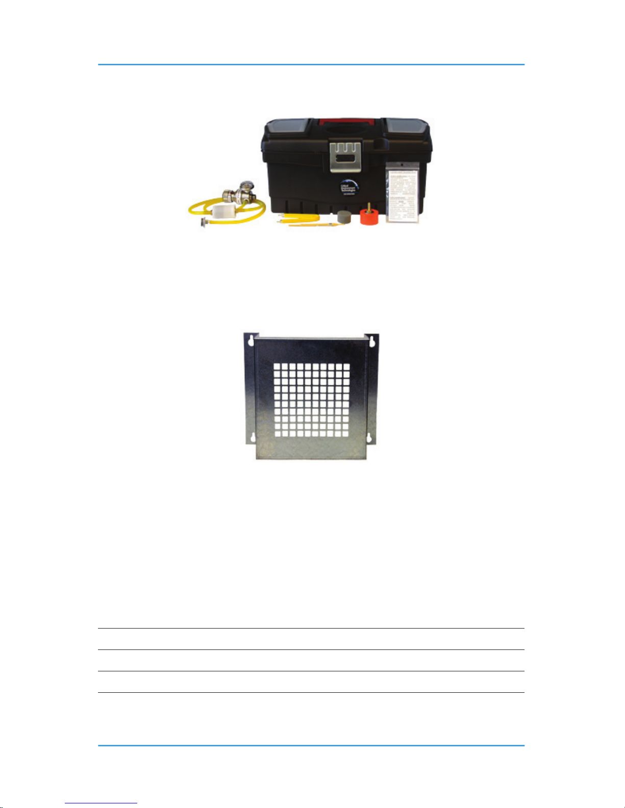
56 © 2014 All rights reserved. Data subject to change without notice.
GEM-II - Operation Manual Rev. E | 2014.10
9 ACCESSORIES
9.1 Calibration Kit
Calibration kits and gases are available from the CETCI factory. Many gases are carried in
inventory but not all. Check with any CETCI authorized distributor for availability of specic gas
types. Gas cylinders cannot be shipped overseas. Part number CET-715A-CK1.
9.2 Metal Protective Guard
The metal protective guard is heavy duty metal protective guard to help protect against abrasive
damage, theft and vandalism to the transmitters. This is an added preventative in addition to
the product enclosure.
It is made from 16-gauge galvanized steel and has ½” (13 mm) square openings in the front
to allow gas and air to ow through to the sensor. With only four slotted mounting holes,
installation and removal for gas detector servicing is easy.
Enclosure 16 gauge galvanized steel
Weight 1.7 kg (3.8 lbs)
Size 10.0” W x 9.5” H x 4.75” D (254 mm W x 241 mm H x 121 mm D)
Page 57

© 2014 All rights reserved. Data subject to change without notice. 57
Rev. E | 2014.10 GEM-II - Operation Manual
10 MAINTENANCE
The GEM series system requires virtually no maintenance other than regular calibration of the
integral and / or remote sensors and ensuring that excess water or dust is not somehow entering
the enclosure and physically damaging the circuit board or internal components.
Page 58

58 © 2014 All rights reserved. Data subject to change without notice.
GEM-II - Operation Manual Rev. E | 2014.10
NOTES
Page 59

© 2014 All rights reserved. Data subject to change without notice. 59
Rev. E | 2014.10 GEM-II - Operation Manual
NOTES
Page 60

Critical Environment Technologies Canada Inc.
Unit 145, 7391 Vantage Way, Delta, BC, V4G 1M3, Canada
Toll Free: +1.877.940.8741
Tel: +1.604.940.8741
Fax: +1.604.940.8745
www.critical-environment.com
© 2014 Critical Environment Technologies Canada Inc. All rights reserved. Data in this publication may change without notice.
GEM20141003-E
 Loading...