

Critical Environment Technologies PDC Series, DST Series Installation And Operation Manual
Critical Environment Technologies Canada Inc.
“PDC” Series Programmable Digital Controllers &
“DST” Series Digital Sensor / Transmitters
INSTALLATION / OPERATION MANUAL
Critical Environment Technologies Canada Inc.
Unit 145, 7391 Vantage Way Delta, BC V4G 1M3
Canada Ph: 604-940-8741 Fx: 604-940-8745
REV: E May 20, 2008
www.critical-environment.com
1

IMPORTANT NOTICES
READ AND UNDERSTAND THIS OPERATION MANUAL PRIOR TO INSTALLING OR USING THIS INSTRUMENT. THE
MANUFACTURER IS NOT RESPONSIBLE FOR ERRORS AND PROBLEMS RESULTING FROM THE USE OF THE
WRONG TYPE AND GUAGE WIRE/CABLE OR PROGRAMMING CHANGES MADE BY UNTRAINED OR UNAUTORIZED
INSTALLERS OR END USERS.
THIS EQUIPMENT SHOULD BE INSPECTED AND MAINTAINED BY A QUALIFIED AND TRAINED TECHNICIAN. FOR
MORE INFORMATION REFER TO OTHER SECTIONS OF THIS MANUAL.
THIS INSTRUMENT HAS NOT BEEN DESIGNED TO BE INTRINSICALLY SAFE OR EXPLOSION-PROOF. FOR YOUR
SAFETY, DO NOT INSTALL IT OR USE IT IN CLASSIFIED HAZARDOUS AREAS (EXPLOSION-RATED ENVIRONMENTS).
THIS MANUAL INCLUDES INSTALLATION, OPERATION AND TROUBLE-SHOOTING DETAILS AND SPECIFICATIONS
FOR THE PDC SERIES CONTROLLER AS WELL AS THE DST SERIES DIGITAL SENSOR / TRANSMITTERS, WHICH
ARE USED EXCLUSIVELY WITH THE PDC CONTROLLER.
WARNINGS
••••
THE TYPE AND GUAGE OF WIRING AND PROPER INSTALLATON OF THE SAME IS CRITICAL TO THE PROPER
OPERATION OF A COMPLETE PDC GAS DETECTION SYSTEM
••••
ANY PROGRAMMING CHANGES SHOULD BE MADE ONLY BY TRAINED AND AUTHORIZED TECHNICIANS
••••
DISCONNECT POWER BEFORE SERVICING
••••
CAUTION: MORE THAN ONE LIVE CIRCUIT
••••
SUPPLY: 90 TO 250 VAC, 47 TO 63 HZ.
••••
CERTIFIED FOR ELECTRICAL SHOCK AND ELECTRICAL FIRE HAZARD ONLY (CSA / UL CERTIFIED)
••••
SENSOR LIFE SPAN AND ACCURACY IS DEPENDENT UPON MANY THINGS INCLUDING APPLICATION AND
CALIBRATION MAINTENANCE. REFER TO CALIBRATION SECTION OF THIS MANUAL FOR CALIBRATION
MAINTENANCE FREQUENCY
••••
WARRANTY POLICY
CRITICAL ENVIRONMENT TECHNOLOGIES CANADA INC. WARRANTS THE PDC CONTROLLERS AND DST
TRANSMITTERS TO BE FREE FROM DEFECTS IN MATERIALS AND WORKMANSHIP FOR A PERIOD OF TWO (2)
YEARS FROM THE DATE OF SHIPMENT FROM OUR FACILITY. ELECTROCHEMICAL SENSOR ELEMENTS, OTHER
THAN HVAC CARBON MONOXIDE (CO) ARE WARRANTED FOR ONE (1) YEAR FROM THE DATE OF SHIPMENT FROM
OUR FACILITY. HVAC CO SENSORS ARE WARRANTED FOR TWO YEARS. WARRANTY REPLACEMENT FOR ALL
ELECTROCHEMICAL SENSORS IS ON A “PRO-RATED” BASIS. THE WARRANTY STATUS MAY BE EFFECTED IF ANY
OF THIS EQUIPMENT HAS NOT BEEN INSTALLED PROPERLY OR MAINTAINED AS PER THE INSTRUCTIONS
INDICATED IN THIS MANUAL OR HAS BEEN ABUSED OR DAMAGED IN ANY WAY. THIS INSTRUMENT IS ONLY TO BE
USED FOR PURPOSES STATED HEREIN. WARRANTY DOES NOT INCLUDE THIRD PARTY TROUBLE-SHOOTING
COSTS OR FREIGHT TO OR FROM OUR FACILITY. OUR LIABILITY IS LIMITED TO REPLACEMENT OR REPAIR OF THE
EQUIPMENT WE MANUFACTURE.
2

INDEX
SECTION DESCRIPTION PAGE
1.0 General .................................................................................. 4
2.0 Controller Specifications ..................................................... 4-5
2.1 Wiring Specifications & Installation Instructions .............. 5
3.0 Installation (including sensor mounting heights).............. 6
3.1 Wiring .................................................................................... 6-7
3.2 Jumper Settings & Wiring Examples .................................. 7-8
4.0 Enclosure Outer Dimensions Drawing ............................... 9
4.1 Enclosure Interior Layout Drawing ..................................... 10
4.2 Wiring Connections Drawing (Digital) ................................ 11
4.3 Wiring Connections Drawing (Analog) ............................... 12
4.4 DST Digital Electrochemical Sensor/Transmitter Drawing 13
4.5 DST Digital Solid-State Sensor/Transmitter Drawing ........ 14
5.0 Main Circuit Board Photo (Digital) ...................................... 15
5.1 Main Circuit Board Photo (Analog) ..................................... 16
5.2 DST Circuit Board Photo (Electrochemical)....................... 17
5.3 DST Circuit Board Photo (Solid-State) ............................... 17
6.0 System Operation................................................................. 18
7.0 System Programming—General.......................................... 19
7.1 System Programming—Input Codes .................................. 19
7.2 System Programming—Input Codes Descriptions............ 20-23
7.3 System Programming—Output Codes ............................... 24
7.4 System Programming - Output Code Descriptions ........... 25-29
8.0 Calibration of DST sensor/transmitters .............................. 30
9.0 Peripheral Devices ............................................................... 31
10.0 Adding Analog Transmitters To An Existing System........ 31
11.0 Model & Part Numbers ......................................................... 32-34
12.0 Trouble-Shooting..................................................................
3

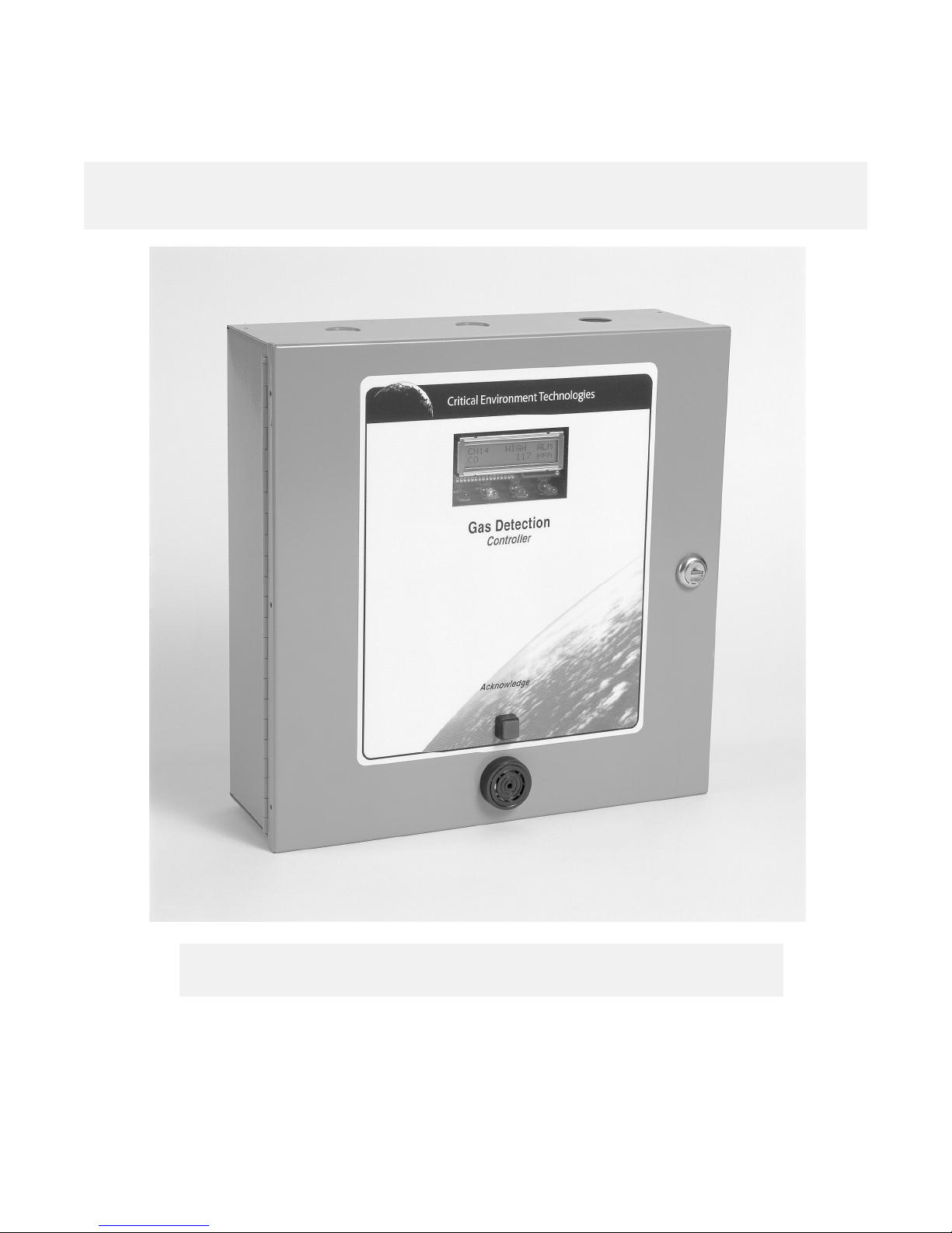
1.0 GENERAL
PDC series systems are configurable, digital, microprocessor based, controllers for use in non-hazardous (non-explosion rated) environments
for commercial and industrial applications. They are available in several basic configurations. One to eight analog channels, one to sixteen
digital channels, one to thirty-two digital channels, one to sixty-four digital channels, one to ninety-six digital channels, one to one hundred and
twenty-eight digital channels.
NOTE: Only the first eight system channels can be utilized for analog inputs.
A basic system provides one common set of LED indicating lights for “Power”, “Fail”, “Low (Warning) Gas Alarm”, “Mid Gas Alarm, “High Gas
Alarm”, an integral audible alarm with silence push-button, scrolling, backlit, 2-line LCD digital display, eight dry contact relays, user
configurable circuit and RS485, 4-wire “multi-drop” wiring. An eight channel version is also available for use with conventional analog
transmitters.
A good selection of electrochemical, MOS (Metal Oxide Semi-conductor) solid-state, and catalytic sensor / transmitters (digital and analog) are
available for use within the PDC series controllers.
2.0 CONTROLLER SPECIFICATIONS
Physical: Standard:
a) Dimensions: 12.0” Wide X 12.0” High X 4.0” Deep (311 mm Wide X 311 mm High X 106 mm
(Deep)
b) Weight: 3.49 pounds (1.585 kg)
Water/dust tight:
a) Dimensions: TBA
b) Weight: TBA
Materials: Standard: Rugged 18 gauge powder painted metal with hinged, secured key-lock door and Lexan
door label. General purpose rating.
Water/dust tight: Fiberglass reinforced polyester
Visual: a) Common set of LED indicating lights for:
* Power (green)
* Fail (red)
* Low (Warning) Gas Alarm (amber)
* Mid (Intermediate) Gas Alarm (red)
* High Gas Alarm (red)
b) Two-line, sixteen character, backlit LCD digital display for sensor/channel information,
quantitative readings and alarm status.
c) Amber colored LED relay coil status indicators (8-leads)
d) Red colored LED “loop” indicators for analog version (8-leads)
Audible: Integral, door mounted sonalert with silence push-button. Rated 90 dB @ 10’
Environment: a) Temperature: 0 deg. C. to +40 deg. C. (32 deg. F. to 104 deg. F.)
b) Humidity: 0 to 95% non-condensing
Power: 90 to 250 VAC, 47 to 63 Hz
Current Load: Maximum allowable system current load: 1.36 Amps @ 24 VDC (power supplied to remote transmitters)
Relays: Standard: Eight only S.P.D.T. dry contact relays, rated 5 amps @ 240 VAC each.
Outputs: a) Strobe: 24VDC alarm level activated MAXIMUM 400 mA (global alarm control)
b) Auxiliary: 24VDC alarm level activated MAXIMUM 400 mA (global alarm control)
4

2.0 CONTROLLER SPECIFICATIONS, CONT’D…..
Fuses: Replaceable: Primary: 1.5 amp, Power supply: 2.0 amp
Options: a) Remote mounted 4” diameter strobe light
b) Remote mounted combination strobe light/siren alarm
c) Remote mounted 5” industrial horn (115VAC)
d) Water/dust tight, corrosion resistant system enclosure
e) Remote relay module
f) Remote analog output module
g) Remote annunciator (remote display)
h) Remote power supply
2.1 WIRING SPECIFICATIONS & INSTALLATION INSTRUCTIONS
PDC controller: should be installed in a locked electrical room to prevent vandalism. There are three knockouts located along the top edge and
three along the bottom edge of the control enclosure for conduit entry. Use caution when punching out knock outs to avoid contact and damage
to circuit boards.
Wiring specifications: are critical to the proper operation of a digital system. The wiring consists of a 2-conductor, 14 gauge, stranded wire
for 24V power and COM plus 2-conductor, 18 gauge, shielded, low capacitance, “twisted-pair” for communications (Data-A and Data-B).
Alternative: Belden Device Net Cables (reference the info package supplied with all PDC controllers).
All wiring must be installed in conduit according to local electrical codes. System problems arising from the installation and/or use of wire or
cable not specified herein are not covered under warranty.
Wiring connections: for the DST transmitters and CAN Network bridges must be “daisy-chained”. This means four wires going into the
device and connected to the “IN” side of the wiring terminal strip and four wires connected to the “OUT” side of the wiring terminal strip and
going out of the device and on to the next device. This is the only acceptable method of termination. Double check to ensure the data-A and
data-B lines of the BUS wiring are not crossed from transmitter to transmitter.
Wiring shield: from the 2-conductor, shielded, twisted-pair portion of the wiring must be connected to the PDC negative connection located
at the bottom right corner of the PDC board “BATT BACK-UP” terminal strip. At each DST or CAN, the shields must be connected together
but not to common or ground. Installed correctly, this creates a continuous shield from the PDC to the last transmitter on the wiring run. At
the last DST transmitter on the wiring run, the shield must be left floating. It is grounded at one point only and that is the PDC controller.
DST digital transmitters: DST transmitters are digital gas transmitters with built-in sensors for various gases. Carbon Monoxide (CO) sensor
versions should be installed at 4’ to 6’ from the floor. The DST digital transmitters with Propane (C3H8) sensors should be installed at 6” from
the floor. The DST digital transmitters with Nitrogen Dioxide (NO2) sensors should be installed at 4’ to 6’ from the floor. Consult the manual
for mounting heights for other gas sensor types. Conduit can enter the DST enclosures from the back of the base or from the top or bottom of
the base. Take care when installing conduit to avoid damaging the electronic circuits. Problems arising from damage to circuit board during
installation are not covered under warranty.
CAN Network bridges: CAN network bridges act as “repeaters” for the data communications by reassembling the data (correcting any
potential corruption that may have occurred in the data along the wiring run) and sending it on to the DST or PDC. They MUST be installed
every 1000’ of wire (cable). If the distance is longer than 1000’ communication problems could occur. The installer must also consider any
loops and corners in calculating this distance for a total of no more than 1000’. Conduit can enter the CAN enclosures from the back of the
base or from the top or bottom of the base. Take care when installing conduit to avoid damaging the electronic circuits. Problems arising from
damage to circuit board during installation are not covered under warranty.
Remote power supplies: Remote power supplies are used to “boost” the 24VDC power wiring to compensate for voltage drops created by
extra resistance from long wiring runs. It is critical that the DST transmitters receive at least 20 to 24 VDC. The power supply MUST be
installed at approximately 2/3 of the way along any one wiring run. Example: If a specific wiring run from the PDC controller is 2500’ to the last
DST, the power supply must be installed at approximately the 1600’ area. The power supply “boosts” the voltage to transmitters “down line”
from it as well as increasing voltage to the “up line” transmitters closest to it.
NOTE: The remote power supply requires 120VAC line voltage power. The output from this power supply is a regulated 24VDC and it MUST
be parallel connected, at a DST transmitter, to the 24VDC supply wires coming from the PDC controller. This means the positive output of the
remote power supply must be connected to the positive 24V line of the BUS wiring and the negative output of the remote power supply must
be connected to the “COM” line of the BUS wiring.
Jumpers: must be placed on the correct terminals of the PDC controller as well as the last (end-of-line termination) DST transmitter on any
wiring run. Jumpers must also be utilized in the CAN network bridges. Jumpers can be found in a plastic bag attached to the inside of the PDC
controller. Correct jumper placement is critical to good communication along the BUS wiring system. Reference the jumper placement
examples on pages 12 of this manual.
5

3.0 INSTALLATION
Standard: Four 3/16” diameter mounting holes can be located at the corners inside the enclosure base. Take caution when using installing
tools inside system enclosure to avoid damaging internal components.
Water/dust tight: These enclosures are optional and are supplied with four mounting feet that must be attached by the installer. A liquid tight
conduit fitting must be used to maintain the water tight state of this enclosure.
Security: PDC should be installed inside a locked electrical, mechanical or instrumentation room. In the event that it is installed in a less secure
area, the enclosure has a key locking, hinged door.
NOTE-1: Care should be taken to avoid installing controllers in areas that present a lot of potential for EMI (electromagnetic interference) and
RFI (radio frequency interference). The system metal enclosure will provide a certain amount of RFI protection. Damage to controller circuitry
from over exposure to large amounts of EMI and RFI are not covered under warranty.
NOTE-2: The PDC controller is available configured for either eight analog inputs, or sixteen, thirty-two, sixty-four, ninety-six or one hundred
and twenty-eight digital inputs. PDC circuit boards can be supplied for analog transmitters or for digital transmitters or for both. The digital
output terminal strip is required if the PDC is to communicate to a remote annunciator panel.
NOTE-3: The preferred installation involves installing the transmitter with the lowest ID code number representing channel-1 on the controller,
the next consecutive ID code number representing channel-2 on the controller and so on. THIS IS HOW THE CONTROLLER IS ALWAYS
PROGRAMMED AT THE FACTORY. ID addresses 1 to 8 are reserved for analog transmitters. ID addresses 9 to 128 are reserved for
digital transmitters.
Sensor Head Mounting Heights
Carbon Monoxide: 4’ to 6’ from the floor
Nitrogen Dioxide: 4’ to 6’ from the floor (garage applications)
Propane: 6” from the floor
Methane / Hydrogen: On or near the ceiling
Refrigerants (Freons): 6” from the floor or near the most probable leak source
Ammonia: On or near the ceiling
Chlorine: 6” from the floor
Ozone: 6” to 24” from the floor
Oxygen: 4’ to 6’ from the floor
Hydrogen Sulphide: 3” to 5” from the floor
Sulphur Dioxide: 6” from the floor
Nitric Oxide: 4’ to 6’ from the floor
Ethylene Oxide: 6” to 12” from the floor (application dependent)
Environment
If sensor heads or controller are to be installed in a wet environment optional water/dust tight, corrosion resistant enclosures are available. If
sensor may be subject to splashed liquid, optional splash guards are available. TO MAINTAIN WATER/DUST TIGHT RATING OF
ENCLOSURES, LIQUID TIGHT CONDUIT FITTINGS MUST BE UTILIZED. FOLLOW INSTALLATION INSTRUCTIONS CAREFULLY.
CORROSION DAMAGE FROM IMPROPERLY INSTALLED ENCLOSURES IS NOT COVERED UNDER WARRANTY.
3.1 WIRING
Line Voltage Power to System: Three knock-outs have been provided along the top edge and three along the bottom edge of the enclosure
base for conduit and wire entry. Take caution when “punching” out metal knockouts and installing conduit connections to avoid
damaging internal system components. The interior of the PDC is divided into two general sections with regards to voltages. The “line
voltage section” is located at the top right corner and right hand side of the enclosure interior. The “low voltage section” is located across the
bottom and up the left side of the system enclosure.
A large terminal strip and ground studs have been provided, at the top right corner of system enclosure interior, to secure line power and
ground wires. Take note of power requirements as listed in “CONTROLLER SPECIFICATIONS” on page-4.
Low Voltage Power to Sensor / Transmitters:
Analog System: If an analog system has been selected, wiring should consist of 2-conductor 14-16 gauge wire for 24V nominal supply to
remote sensor / transmitters. If wiring runs are more than 1000’, use 14 gauge stranded wire. The 24V supply can be daisy-chained to the
remote sensors. The wiring terminal strip for the 24V supply can be found at the bottom left edge (low voltage section) of the circuit board. The
analog signal loop consists of one signal wire for each sensor. These wires can usually be 16 to 18 gauge. Signal wires should be shielded if
they are not to be run within conduit. The wiring terminal strip for the signal wires can be found at the left lower side (low voltage section) of the
circuit board. Refer to section 4.3, page-12 for a detailed wiring drawing.
6

3.1 WIRING
Digital System: If a digital system has been selected, refer to “WIRING SPECIFICATIONS AND INSTALLATION INSTRUCTIONS” on page
5. The wiring terminal strip for the digital system can be found at the bottom middle edge of the circuit board. Refer to section 4.1, page-10 for
a detailed wiring drawing.
NOTE-1: Do not use solid-core wire at circuit board terminals. Solid-core wire has memory and can tear a soldered terminal right off the circuit
board. This is not covered under warranty.
NOTE-2: Common, accepted wire colors for positive, negative and signal VDC wires are: Red for positive, Black for negative and White or
Yellow for signal.
NOTE-3: 14 gauge wire should be utilized for longer wire runs to minimize voltage drop.
NOTE-4: All wiring must be “daisy-chain” installed. All four wires must go to the input terminal of a digital transmitter or CAN network bridge
and must exit the output terminal strip to go onto the next transmitter or CAN network bridge.
NOTE-5: It is imperative that a termination jumper is placed on the last transmitter on the wiring run (end-of-line). The jumper terminates the
resistor installed on the DST circuit board. The resistor installed on the PDC circuit board provides termination at the beginning of the wiring
run. A jumper termination is also required for any CAN network bridges installed. Consult “JUMPER SETTINGS AND WIRING EXAMPLES”
below.
Relay Wiring: Both analog and digital systems are supplied with dry contact relays for control of remote devices such as exhaust fan and make
up air fan contactors, etc. The relay wiring terminal strips are located along the right side (line voltage side) of the circuit board. Take note of
the maximum relay specifications as listed in section 2.0 when connecting load devices. With regards to fans, relays should be used to control
fan starters or contactors and NOT the fan motor directly. If device to be controlled is a higher voltage or current than the system relays are
capable of handling, use a heavier rated, external dry contact relay to handle the heavier load and use the relay contacts inside the PDC to
activate the coil on the external relay.
NOTE: STAR-WIRING CONFIGURATIONS CANNOT BE USED ON THIS SYSTEM. PROBLEMS ARISING FROM USING SUCH A WIRING
CONFIGURATION ARE NOT THE RESPONSIBILOITY OF CETCI.
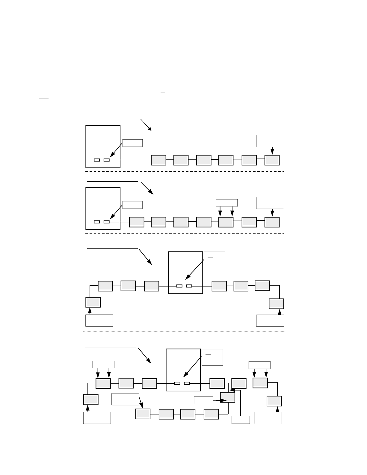
3.2 JUMPER SETTINGS AND WIRING EXAMPLES
The PDC circuit design is such that the relay coils can be selected as “normally energized” or “normally de-energized”. Unless advised, the
factory default is “normally energized” in non gas alarm condition. Thus, control wiring should be connected to “COM” and “N/C”. In the event
of a hardware, wiring or sensor failure (solid-state sensor only), the relay coil changes state and the device being controlled operates
continuously until the fault condition is corrected. Consult the programming sheet supplied with the controller for the factory program that was
set up.
Example-2: One run of system wiring at approximately 1800’ from the PDC controller out to a number of DST transmitters with one CNB
network bridge installed at the 1000’ point along the BUS wiring. One jumper is placed at “J5” jumper pin location for (“IN”) or (“OUT”) inside
the PDC controller, depending on which wiring terminal strip is utilized. The “IN” or the “OUT” can be used for the system wiring. They are
paralleled inside the circuit. One jumper is placed at the “J2” jumper pin location and one jumper is placed at the “J3” jumper pin location inside
the CNB bridge. One jumper is placed at the “J2” jumper pin location inside the DST transmitter located at the end of the system wiring run.
Example-3: Two runs of system wiring, one from the “IN” and one from the “OUT” wiring terminals inside the PDC. Each wiring run is 500’ long.
No jumper is to be used at the “J5” jumper pin location inside the PDC. One jumper is placed at the “J2” jumper pin location inside the DST
transmitter located at the end of each of the system wiring runs.
Example-4: Two runs of system wiring, one from the “IN” and one from the “OUT” wiring terminals inside the PDC. Each wiring run is 1000’
long. Two CNB bridges are required. No jumper is to be used at the “J5” jumper pin location inside the PDC. One jumper is placed at the “J2”
jumper pin location inside the CNB bridge and One jumper is placed at the “J3” jumper pin location inside the CNB bridge. One jumper is
placed at the “J2” jumper pin location inside the DST transmitter located at the end of each system wiring run.
The “T” drop can be achieved but requires a CNB bridge for every “T” drop. One jumper is placed at the “J3” jumper pin location only inside the
CNB bridge. One jumper is placed at the “J2” jumper pin location inside the DST transmitter located at the end of the system wiring run.
NOTE: “T” DROPS ARE NOT RECOMMENDED FOR PDC SYSTEM WIRING.
Termination jumpers are required in various areas to ensure communication is established between the PDC controller and the various
transmitters and peripheral devices.
7
3.2 JUMPER SETTINGS AND WIRING EXAMPLES, CONT’D…..
System wiring can originate at the “CAN-IN” or “CAN-OUT” wiring terminals of the PDC. They are parallel connected internally. System wiring
can also originate at both and run in two directions to save on conduit and wire.
Several installation examples are described below with correct jumper positions indicated. See the page-12 for diagram layouts to match the
examples described below.
Example-1: One run of system wiring at or under 1000’ from the PDC controller out to a number of DST transmitters with no CNB bridges
required and no remote power supply required. One jumper is placed at “J5” jumper pin location for (“IN”) or (“OUT”) inside the PDC controller,
depending on which wiring terminal strip is utilized. The “IN” or “OUT” terminals can be used for system wiring. They are paralleled inside the
circuit. One jumper is placed at the “J2” jumper pin location inside the DST transmitter located at the end of the system wiring run.
Installation Example-1:
PDC
END-OF LINE
JUMPER
JUMPER
J5
Installation Example-2:
PDC
JUMPER
J5
DST
Installation Example-3:
DST
DST
END-OF LINE
JUMPER
DST
PDC
J5
DST DST DST
DST DST DST
“NO”
JUMPERS
HERE
JUMPERS
DST DST
DST
DST DST DST
END-OF LINE
JUMPER
DST DST CNB-1
DST
DST
END-OF LINE
JUMPER
Installation Example-4:
JUMPERS
CNB-1
DST
END-OF LINE
JUMPER
DST
END-OF LINE
JUMPER
DST
PDC
J5
“NO”
JUMPERS
HERE
JUMPER
JUMPERS
DST DST
DST DST DST
DST
CNB-3
NODE-1
CNB-2
DST
END-OF LINE
JUMPER
8
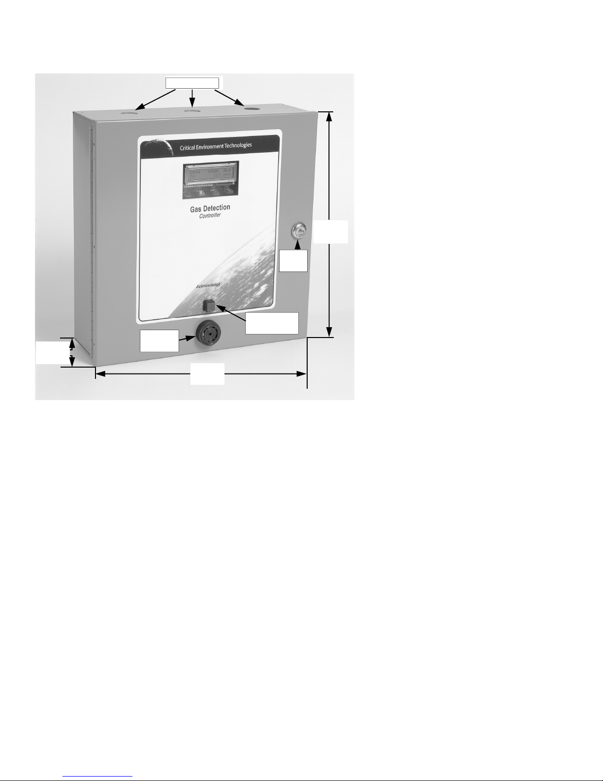
4.0 ENCLOSURE OUTER DIMENSIONS
KNOCKOUTS
KNOCKOUTS
AUDIBLE
4.19””
106 mm
ALARM
12.25”
311 mm
KEY
LOCK
SILENCE
PUSH-BUTTON
12.25”
311 mm
NOTE-1: Three knockouts can be found along the top edge and three along the bottom edge of the system enclosure
NOTE-2: Standard enclosure is powder painted, 18-gauge steel with locking, hinged door. Optional water/dust tight, corrosion resistant
enclosures for harsher environments are available. Consult your local authorized distributor for more details.
9
4.1 ENCLOSURE INTERIOR LAYOUT PHOTO
RELAY WIRING TERMINALS
ENCLOSURE
MOUNTING
HOLE
INCOMING
LINE VOLTAGE
SYSTEM
POWER
TOP OF
ENCLOSURE
>>>
ENCLOSURE
MOUNTING
HOLE
PROGRAMMING
PUSH-BUTTONS
WIRING TERMINALS
FOR STROBE, ETC.
MAIN FUSE
ENCLOSURE
MOUNTING
HOLE
24VDC FROM
INTERNAL
SWITCHING POWER
SUPPLY
WIRING
TERMINALS
FOR DIGITAL
SENSORS
ENCLOSURE
MOUNTING
HOLE
WIRING TERMINALS
AREA
FOR OPTIONAL
ANALOG SENSORS
10

4.2 WIRING CONNECTIONS DRAWING (DIGITAL)
11
 Loading...