

Page 1
Rev. A | 2019.07
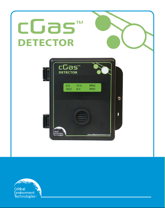
cGas Detector Digital Transmitter
Operation Manual
www.critical-environment.com
Page 2

cGas Detector Digital Transmitter - Operation Manual Rev. A | 2019.07
TABLE OF CONTENTS
1 POLICIES ..........................................................................................................5
1.1 Important Note ................................................................................................5
1.2 Warranty Policy ................................................................................................6
1.3 Service Policy ...................................................................................................7
1.4 Copyrights ........................................................................................................8
1.5 Disclaimer ........................................................................................................8
1.6 Revisions ..........................................................................................................8
2 INTRODUCTION .............................................................................................9
2.1 General Description ..........................................................................................9
2.2 Key Features ...................................................................................................10
3 INSTRUMENT SPECIFICATIONS .................................................................11
3.1 Technical Speci cations ..................................................................................11
3.2 Enclosure Dimensions ....................................................................................14
4 SENSOR SPECIFICATIONS ...........................................................................15
4.1 Single Channel Gas Sensor Options ................................................................15
4.2 Dual Channel Gas Sensor Options ...................................................................17
4.3 Calibration Extending Firmware (CEF) and Sensor Aging................................18
5 INSTRUMENT FEATURES .............................................................................18
5.1 Exterior Enclosure ..........................................................................................18
5.2 Interior System Layout ................................................................................... 19
6 SYSTEM OPERATION & CONFIGURATION ................................................20
6.1 Navigating the Menu Structure ......................................................................20
6.2 Accessing the Menu with Passcodes ...............................................................21
2 © 2019 All rights reserved. Data subject to change without notice.
Page 3

Rev. A | 2019.07 cGas Detector Digital Transmitter - Operation Manual
6.3 Display Settings .............................................................................................22
6.3.1 Adjust Display Brightness ................................................................................23
6.3.2 Display Con gurations ....................................................................................23
6.3.3 Display or Hide Line 1 and/or 2 .......................................................................24
6.4 Alarm Status, Fault Detection and Communication Failure Noti cations ........25
6.5 Setting Channel Alarm Setpoints, Direction and Hysteresis ............................26
6.6 Enable / Disable Channels ..............................................................................29
6.7 Change Units (degC or degF) of Temperature Readings .................................. 30
6.8 Temperature and/or Relative Humidity O set ................................................ 31
6.9 Test Functions ................................................................................................ 32
7 MODBUS AND BACNET CONFIGURATION...............................................34
7.1 Changing Communication Type (Modbus®/BACnet®) in the Field ..................34
7.2 Con guring Modbus® Settings .......................................................................35
7.2.1 Change Modbus® MAC Address .......................................................................35
7.2.2 Change Baud Rate ........................................................................................... 36
7.2.3 Modbus® Holding Registers ............................................................................37
7.3 Con guring BACnet® Settings ........................................................................ 37
7.3.1 Change BACnet® MAC Address ........................................................................37
7.3.2 Change BACnet® Instance ID ...........................................................................38
7.3.3 Change BACnet® Baud Rate .............................................................................38
7.3.4 BACnet® PICS Information ...............................................................................39
8 PLUG & PLAY SMART SENSOR REPLACEMENT .......................................46
8.1 How to Replace or Add a New Smart Sensor Board ........................................46
8.2 Read from Sensor ...........................................................................................47
8.3 Write to Sensor ...............................................................................................49
© 2019 All rights reserved. Data subject to change without notice. 3
Page 4

cGas Detector Digital Transmitter - Operation Manual Rev. A | 2019.07
9 CALIBRATION ................................................................................................49
9.1 Calibration Speci cations ............................................................................... 49
9.1.1 Gas ..................................................................................................................49
9.1.2 Regulators & Flow ........................................................................................... 50
9.1.3 Adapters..........................................................................................................50
9.1.4 Calibration Frequency .....................................................................................50
9.1.5 Gas Testing Frequency (Bump Testing) ............................................................51
9.1.6 Sticky Gases.....................................................................................................51
9.2 Calibrating the Internal Sensor(s) ..................................................................51
9.2.1 Set Calibration Gas Value .................................................................................51
9.2.2 Zero (Null) Calibration .....................................................................................53
9.2.3 Span Calibration ..............................................................................................54
9.3 Troubleshooting Calibration ...........................................................................56
9.3.1 Calibration Adapter Plug Doesn’t Fit ................................................................56
9.3.2 Zero Fault ........................................................................................................ 56
9.3.3 Span (Calibration) Fault ................................................................................... 57
9.3.4 Zero Override ...................................................................................................57
9.3.5 Span Override..................................................................................................57
9.4 Calibrating an Oxygen Sensor ........................................................................58
10 ACCESSORIES .............................................................................................60
10.1 Splash Guard (Option -S) ..............................................................................60
10.2 Calibration Adapter Clip ”Cal Clip” ................................................................ 60
10.3 Splash Guard for Sticky Gases (Option -SN) ..................................................61
10.4 Metal Protective Guard ................................................................................62
10.5 Calibration Kit ..............................................................................................62
11 MAINTENANCE ..........................................................................................63
12 TROUBLE SHOOTING ................................................................................64
4 © 2019 All rights reserved. Data subject to change without notice.
Page 5

Rev. A | 2019.07 cGas Detector Digital Transmitter - Operation Manual
1 POLICIES
1.1 Important Note
Read and understand this manual prior to using this instrument. Carefully read the warranty policy,
service policy, notices, disclaimers and revisions on the following pages.
This product must be installed by a quali ed electrician or factory trained technician and according
to instructions indicated in this manual. This instrument should be inspected and calibrated
regularly by a quali ed and trained technician.
This instrument has not been designed to be intrinsically safe. For your safety, do not use it in
classi ed hazardous areas (explosion-rated environments).
INSTRUMENT SERIAL NUMBER:
______________________________________________________
PURCHASE DATE:
______________________________________________________
PURCHASED FROM:
______________________________________________________
© 2019 All rights reserved. Data subject to change without notice. 5
Page 6

cGas Detector Digital Transmitter - Operation Manual Rev. A | 2019.07
1.2 Warranty Policy
Critical Environment Technologies Canada Inc. (the manufacturer) warrants this gas monitoring
instrument, (excluding sensors, battery packs, batteries, pumps and lters), to be free from defects
in materials and workmanship for a period of two years from the date of purchase from our
facility. The sensors have a warranty period of one year on a pro-rated basis from the date
of purchase from our facility. This warranty is limited to the mechanics of the physical sensor
components and as such, should the sensor become defective within this warranty period, we
will repair or replace it at our discretion. This warranty does not extend to sensors that have been
poisoned by external compounds such as, but not limited to, extreme gas concentrations, paint
fumes, excessive dust, debris, etc. or to sensors that have been improperly zeroed, c alibrated or
altered in any way. If it is determined within 90 days of purchase that a sensor is malfunctioning
or unable to remain calibrated due to no fault of its placement or treatment, the instrument may be
sent back to the factory for a free calibration service.
The warranty status may be a ected if the instrument has not been operated, calibrated or
maintained as per the instructions in the instrument’s Operation Manual or if the instrument has
been abused, damaged or altered in any way. This instrument is only to be used for purposes stated
herein. The manufacturer is not liable for auxiliary interfaced equipment or consequential damage.
Due to ongoing research, development and product testing, the manufacturer reserves the right to
change speci cations without notice. The information contained herein is based on data considered
accurate. However, no warranty is expressed or implied regarding the accuracy of this data.
All goods must be shipped to the manufacturer by prepaid freight. All returned goods (whether
under warranty or not) must be pre-authorized by obtaining a return merchandise authorization
(RMA) number. Contact the manufacturer for an RMA number and the procedures required for
product transport.
6 © 2019 All rights reserved. Data subject to change without notice.
Page 7

Rev. A | 2019.07 cGas Detector Digital Transmitter - Operation Manual
1.3 Service Policy
CETCI maintains an instrument service facility at the factory. Some CETCI distributors / agents may
also have repair facilities; however, CETCI assumes no liability for service performed by anyone
other than CETCI personnel.
Repairs are warranted for 90 days after date of shipment (sensors have individual warranties).
Should your instrument require non-warranty repair, you may contact the distributor from whom it
was purchased or you may contact CETCI directly.
Prior to shipping equipment to CETCI, contact our o ce for an RMA #. All returned goods must be
accompanied with an RMA number.
If CETCI is to do the repair work, you may send the instrument, prepaid, to:
Attention: Service Department
Critical Environment Technologies Canada Inc.
Unit 145, 7391 Vantage Way
Delta, BC, V4G 1M3
Always include your Returned Merchandise Authorization (RMA) number, address, telephone
number, contact name, shipping / billing information, and a description of the defect as you
perceive it. You will be contacted with a cost estimate for expected repairs, prior to the performance
of any service work.
For liability reasons, CETCI has a policy of performing all needed repairs to restore the instrument to
full operating condition.
Pack the equipment well (in its original packing if possible), as we cannot be held responsible for
any damage incurred during shipping to our facility.
© 2019 All rights reserved. Data subject to change without notice. 7
Page 8

cGas Detector Digital Transmitter - Operation Manual Rev. A | 2019.07
1.4 Copyrights
This manual is subject to copyright protection; all rights are reserved. Under international and
domestic copyright laws, this manual may not be copied or translated, in whole or in par t, in any
manner or format, without the written permission of CETCI.
Modbus® is a registered trademark of Gould Inc. Corporation.
BACnet® is a registered trademark of American Society of Heating, Refrigeration and Air
Conditioning (ASHRAE).
1.5 Disclaimer
Under no circumstances will CETCI be liable for any claims, losses or damages resulting from or
arising out of the repair or modi cation of this equipment by a party other than CETCI service
technicians, or by operation or use of the equipment other than in accordance with the printed
instructions contained within this manual or if the equipment has been improperly maintained or
subjected to neglect or accident. Any of the forgoing will void the warranty.
Under most local electrical codes, low voltage wires cannot be run within the same conduit as line
voltage wires. It is CETCI policy that all wiring of our products meet this requirement.
It is CETCI policy that all wiring be within properly grounded (earth or safety) conduit.
1.6 Revisions
This manual was written and published by CETCI. The manufacturer makes no warranty or
representation, expressed or implied including any warranty of merchantability or tness for
purpose, with respect to this manual.
All information contained in this manual is believed to be true and accurate at the time of printing.
However, as part of its continuing e orts to improve its products and their documentation, the
8 © 2019 All rights reserved. Data subject to change without notice.
Page 9

Rev. A | 2019.07 cGas Detector Digital Transmitter - Operation Manual
manufacturer reserves the right to make changes at any time without notice. In addition, due to
improvements made to our products, there may be information in this manual that does not exist
in the version of the product the user has. Should you detect any error or omission in this manual,
or should you want to inquire regarding upgrading the device’s rmware, please contact CETCI at
the following address:
Critical Environment Technologies Canada Inc.
Unit 145, 7391 Vantage Way, Delta, BC, V4G 1M3, Canada
Toll Free: +1.877.940.8741
Telephone: +1.604.940.8741
Fax: +1.604.940.8745
Email: [email protected]
Website: www.critical-environment.com
In no event will CETCI, its o cers or employees be liable for any direct, special, incidental or
consequential damages resulting from any defect in any manual, even if advised of the possibility
of such damages.
2 INTRODUCTION
2.1 General Description
Thank you for purchasing our cGas Detector Transmitter. The cGas Detector is a one or two channel
gas detection transmitter that o ers exible customization options with the purpose of meeting
your speci c application and budgetary requirements. Ideal for monitoring toxic, combustible and
refrigerant gases in non-hazardous (non-explosion rated) environments such as enclosed parking
facilities, commercial HVAC, greenhouses, recreational facilities, refrigeration plants, manufacturing
plants and other light industrial applications.
The sensors utilized in this device are accurate enough to measure to Occupational Health & Safety
© 2019 All rights reserved. Data subject to change without notice. 9
Page 10

cGas Detector Digital Transmitter - Operation Manual Rev. A | 2019.07
(OHS) hazardous levels for toxic gases. The transmitter operates by di usion.
2.2 Key Features
• 1 or 2 gas channel operation
• User con gurable Modbus® RS-485 RTU or BACnet® MS/TP communication protocols for
communication with a Controller or Building Automation System (BAS)
• Easy Plug & Play Smart sensor replacement at end of life
• Customizable sensor and option combinations to meet speci c application requirements
• 24 volt DC or (ground referenced) AC power
• 4-conductor shielded network wiring (daisy-chain)
• In eld upgradable rmware/con guration via USB connection
• Bright LCD display
• Option -LT: Low temperature package for improved usability in cold environments
• Option -RHT: Relative Humidity and Temperature sensor (digital CO and CO2 models only)
• Option -S: Splash guard, factory installed, IP54 rated enclosure
• Option -SN: Splash guard, factory installed, for Cl2, HCI or O3 sensors only
• Standard water / dust tight, corrosion resistant enclosure (drip proof)
• Copper coated interior to reduce RF interference
• RoHS compliant circuit boards
• Auto resetting fuse
NOTE: Some gas sensor types and Options are restricted to certain models.
If after reading through the manual, you have any questions, please do not hesitate to contact our
service department for technical support.
10 © 2019 All rights reserved. Data subject to change without notice.
Page 11

Rev. A | 2019.07 cGas Detector Digital Transmitter - Operation Manual
3 INSTRUMENT SPECIFICATIONS
3.1 Technical Speci cations
MECHANICAL
Enclosure
Weight 400 g / 14 oz
Size 127 mm x 127 mm x 71 mm / 5.0 in x 5.0 in x 2.8 in
USER INTERFACE
Display (standard)
Display (Option -LT)
USB Port
Push Buttons
Audible Alarm none
ABS / Polycarbonate, IP54 rating with splash guard installed.
Copper coated interior to reduce RF interference.
2-line by 16 character graphic LCD, black on green, text
prompting for calibration operation and fault indications. Installer
con gurable to suppress reading display.
Optional OLED display for improved usability in low temperature
applications, 2-line by 16 character, yellow on black, text
prompting for calibration operation and fault indications. Installer
con gurable to suppress reading display.
Internal port for USB memory stick connection for eld
con guration/ rmware upgrades
Initiate calibration and menu options with internal UP, DOWN and
ENTER push buttons
© 2019 All rights reserved. Data subject to change without notice. 11
Page 12

cGas Detector Digital Transmitter - Operation Manual Rev. A | 2019.07
ELECTRICAL
16 - 30 VDC, 3 W, Class 2
Power Requirement
12 - 27 VAC, 50-60 Hz, 3 VA, Class 2
24V recommended.
Digital Wiring
VDC or VAC (ground referenced) four-conductor shielded 16 AWG
stranded within conduit, network wiring (daisy-chain)
Fuses Automatic resetting thermal
INPUT/OUTPUT
Modbus® ID: 100 (default, con gurable)
Communication
Modbus® RTU (version
1.1b3) RS-485
Baud rate: 19,200 (default, con gurable)
Data bits: 8
Start bits: 1
Stop bits: 1
Parity: none
BACnet® MS/TP; ANSI/ASHRAE standard 135 BACnet®
Communication protocol: 135-2012
Communication
BACnet® MS/TP (version
1 rev 14) RS-485
Baud Rate: 76,800 (default)
Base Address: 270 (default)
MAC Address: 100 (default)
Parity: no parity
Stop bits: 1
Data bits: 8
12 © 2019 All rights reserved. Data subject to change without notice.
Page 13

Rev. A | 2019.07 cGas Detector Digital Transmitter - Operation Manual
RH and Temperature
(Option -RHT)
Available for CO2 and CO models only
ENVIRONMENTAL
Operating Temperature
0°C to 40°C / 32°F to 104°F (standard)
-40°C to 40°C / -40°F to 104°F (with Option -LT)
Operating Humidity 15 - 90% RH non-condensing
Pollution Degree Degree 2
Altitude below 2,000 m
CERTIFICATION
Model: CGAS-D-XXX
S/N: CGASD1807B00010
Rating: 16-30 VDC, 3W, Class 2
12-27 VAC, 50-60 Hz, 3VA, Class 2
CERTIFIED FOR ELECTRIC SHOCK & ELECTRICAL FIRE HAZARD ONLY. LA CERTIFICATION ACNOR
COUVRE UNIQUEMENT LES RISQUES DE CHOC ELECTRIQUE ET D’INCENDIE D’ORIGINE ELECTRIQUE.
Conforms to: CSA-C22.2 No. 205-12, UL508 (Edition 18):2018
Conforms to: EMC Directive 2014/30/EU, EN 50270:2015, Type 1, EN61010
Conforms to: FCC. This device complies with par t 15 of the FCC Rules, Operation is subject to
the following two conditions: (1) This device may not cause harmful interference, and (2) this
device must accept any interference received, including interference that may cause undesired
operation.
© 2019 All rights reserved. Data subject to change without notice. 13
Page 14
cGas Detector Digital Transmitter - Operation Manual Rev. A | 2019.07
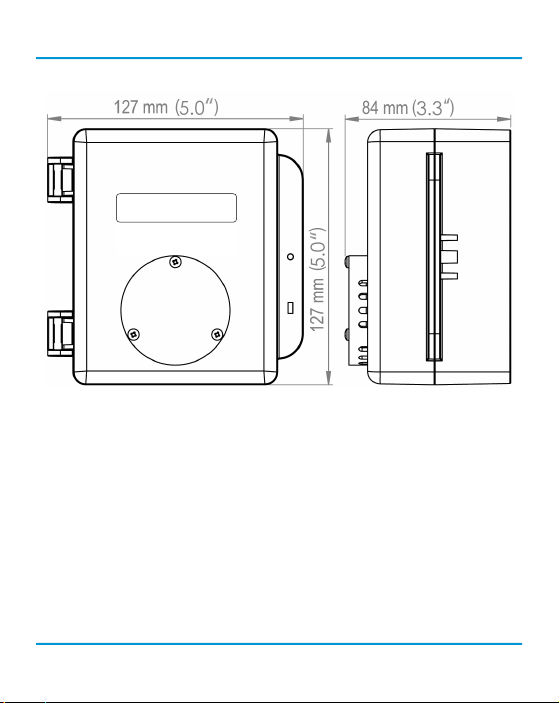
3.2 Enclosure Dimensions
Above dimensions are shown with optional splash guard. Without splash guard, thickness is
71 mm / 2.8 in. The area required for enclosure door to be open 90 degrees is 178 mm / 7.0 in or
254 mm / 10.0 in for fully open. With the optional splash guard installed, the enclosure is IP54
rated.
NOTE: During calibration, the sensor response time will be slower with a splash guard installed.
14 © 2019 All rights reserved. Data subject to change without notice.
Page 15

Rev. A | 2019.07 cGas Detector Digital Transmitter - Operation Manual
4 SENSOR SPECIFICATIONS
4.1 Single Channel Gas Sensor Options
Electrochemical Sensors Part Numbers Range Lifespan
Ammonia (NH3) CGAS-D-NH3 0 - 500 ppm ± 2 years
Carbon Monoxide (CO) CGAS-D-LCO 0 - 200 ppm ± 6 years
Chlorine (Cl2) CGAS-D-CL2 0 - 5.0 ppm ± 3 years
Chlorine Dioxide (ClO2) CGAS-D-CLO2 0 - 1 ppm ± 2 years
Ethylene (C2H4) CGAS-D-C2H4 0 - 200 ppm ± 2 years
Ethylene Oxide (C2H4O) CGAS-D-EETO 0 - 20 ppm ± 2 years
Fluorine (F2) CGAS-D-F2 0 - 1 ppm ± 2 years
Formaldehyde (CH2O) CGAS-D-CH2O 0 - 5 ppm ± 2 years
Hydrogen (H2) CGAS-D-EH2 0 - 2,000 ppm ± 2 years
Hydrogen Sulphide (H2S) CGAS-D-H2S 0 - 50 ppm ± 2 years
Hydrogen Chloride (HCl) CGAS-D-HCL 0 - 30 ppm ± 2 years
Hydrogen Cyanide (HCN) CGAS-D-HCN 0 - 30 ppm ± 2 years
Hydrogen Fluoride (HF) CGAS-D-HF 0 - 10 ppm ± 2 years
Nitric Oxide (NO) CGAS-D-NO 0 - 100 ppm ± 2 years
Nitrogen Dioxide (NO2) CGAS-D-NO2 0 - 10 ppm ± 6 years
Oxygen (O2) CGAS-D-O2 0 - 25% Vol ± 3 years
Ozone (O3) CGAS-D-O3 0 - 2 ppm ± 2 years
© 2019 All rights reserved. Data subject to change without notice. 15
Page 16

cGas Detector Digital Transmitter - Operation Manual Rev. A | 2019.07
Phosphine (PH3) CGAS-D-PH3 0 - 5 ppm ± 2 years
Silane (SiH4) CGAS-D-SIH4 0 - 20 ppm ± 2 years
Sulphur Dioxide (SO2) CGAS-D-SO2 0 - 20 ppm ± 2 years
Refrigerant Sensors Part Numbers Range Lifespan
Refrigerant R22 CGAS-D-SR22 0 - 2,000 ppm ± 5 years
Refrigerant R134A CGAS-D-SR134A 0 - 2,000 ppm ± 5 years
Refrigerant R402A CGAS-D-SR402A 0 - 2,000 ppm ± 5 years
Refrigerant R404A CGAS-D-SR404A 0 - 2,000 ppm ± 5 years
Refrigerant R407A CGAS-D-SR407C 0 - 2,000 ppm ± 5 years
Refrigerant R410A CGAS-D-SR410A 0 - 2,000 ppm ± 5 years
Refrigerant R422D CGAS-D-SR422D 0 - 2,000 ppm ± 5 years
Refrigerant R438A CGAS-D-SR438A 0 - 2,000 ppm ± 5 years
Refrigerant R507A CGAS-D-SR507A 0 - 2,000 ppm ± 5 years
TVOCs CGAS-D-STVOC 0 - 500 ppm ± 5 years
Catalytic Sensors Par t Numbers Range
Hydrogen (H2) CGAS-D-CH2-100 0 - 100% LEL ± 5 years
Methane (CH4) CGAS-D-CCH4-100 0 - 100% LEL ± 5 years
Propane (C3H8) CGAS-D-CC3H8-100 0 - 100% LEL ± 5 years
16 © 2019 All rights reserved. Data subject to change without notice.
Page 17

Rev. A | 2019.07 cGas Detector Digital Transmitter - Operation Manual
PID Sensors Part Numbers Range
TVOC CGAS-D-SPL 0 - 30 ppm
TVOC CGAS-D-SPH 0 - 300 ppm
usage /
application
dependent
Infrared Sensors Part Numbers Range
Carbon Dioxide (CO2)
CGAS-D-CO2-5K 0 - 5,000 ppm
CGAS-D-CO2-5% 0 - 5% vol
± 6 years
4.2 Dual Channel Gas Sensor Options
Two Internal
Electrochemical Sensors
Part Numbers Range Lifespan
Carbon Monoxide (CO) and
Nitrogen Dioxide (NO2)
Carbon Monoxide (CO) and
Ethylene (C2H4)
Carbon Monoxide (CO) and
Hydrogen Sulphide (H2S)
Carbon Monoxide (CO) and
Oxygen (O2)
Carbon Monoxide (CO) and
Nitric Oxide (NO)
© 2019 All rights reserved. Data subject to change without notice. 17
CGAS-D-LCO-NO2
CGAS-D-LCO-C2H4 0 - 200 ppm
CGAS-D-LCO-H2S
CGAS-D-LCO-O2
CGAS-D-LCO-NO
0 - 200 ppm
0 - 10 ppm
0 - 200 ppm
0 - 50 ppm
0 - 200 ppm
0 - 25% vol
0 - 200 ppm
0 - 100 ppm
± 6 years
± 6 years
± 2 years
± 6 years
± 2 years
± 6 years
± 3 years
2-3 years
Page 18
cGas Detector Digital Transmitter - Operation Manual Rev. A | 2019.07
Hydrogen Sulphide (H2S) and
Sulphur Dioxide (SO2)
CGAS-D-H2S-SO2
0 - 50 ppm
0 - 20 ppm
2+ years
4.5 Calibration Extending Firmware (CEF) and Sensor
Aging
The cGas Detector with integral electrochemical sensor(s) have been programmed with our CEF.
This rmware takes into consideration the aging of the electrochemical CO and NO2 sensors so that
less frequent calibrations are required in less-critical applications such as parking garages. The
system tracks the age of the sensor and automatically compensates for the reduced output of the
sensor as it ages.
5 INSTRUMENT FEATURES
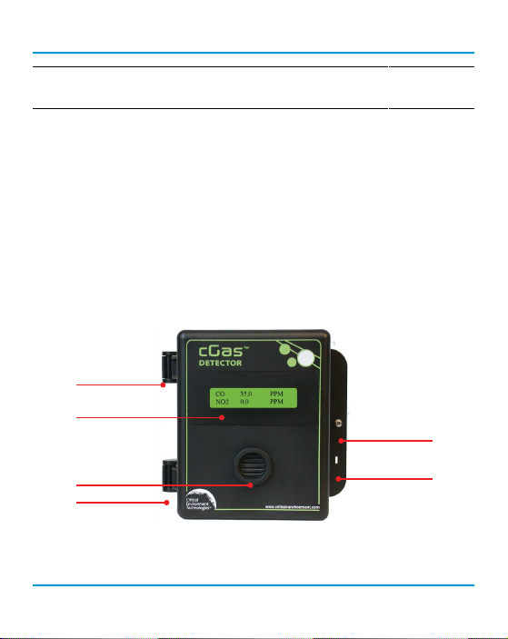
5.1 Exterior Enclosure
Œ
•
•
Ž
Œ
18 © 2019 All rights reserved. Data subject to change without notice.
•
Page 19
Rev. A | 2019.07 cGas Detector Digital Transmitter - Operation Manual
ys yo
NUMBER FEATURE FUNCTION
Œ
•
Ž
•
•
Door Hinge
Display
Sensor Opening
Door Screw S ecures door shut
Lock Slot For security padlock or tie
Secures door to base and allows easy
opening and closing
LCD display (standard display)
A
B
Allows gas di usion into sensor
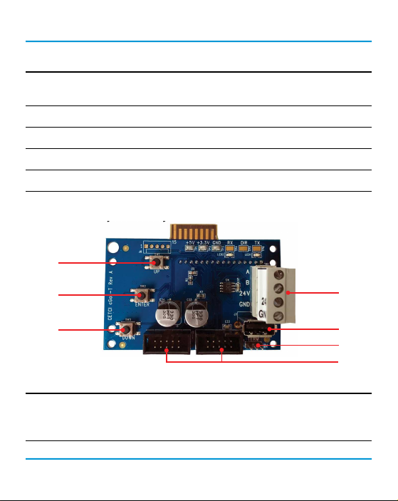
5.2 Interior System Layout
Œ
Œ
Œ
NUMBER FEATURE FUNCTION
Programming Buttons
Œ
© 2019 All rights reserved. Data subject to change without notice. 19
Access menu options and program functions using
buttons inside the enclosure. (Arrow up, Enter, Arrow
down)
•
Ž
•
•
Page 20

cGas Detector Digital Transmitter - Operation Manual Rev. A | 2019.07
RS-485 Communication
•
Terminals
USB Connection For rmware and con guration upgrades
Ž
Termination Resistor
•
Sockets for sensors and
•
Options boards
Pluggable power and signal terminal for connection
to controller and next transmitter.
Network termination resistor. “IN” position includes
120 ohm resistor.
Sensor boards and Options boards plug into the main
board using these sockets
6 SYSTEM OPERATION & CONFIGURATION
The cGas Detector continuously monitors target gas concentrations on one or two con gured
channels. It must be connected to a controller, control panel or BAS / BMS / DDC system; the cGas
Detector is not a standalone gas detection system.
6.1 Navigating the Menu Structure
The three programming push-buttons inside the enclosure are used to navigate through the cGas
Detector menu structure. Refer to Section 5.1 Exterior Enclosure for location photo.
ENTER begins a process or moves you to the next screen in the same menu.
The UP or DOWN buttons are used to enter characters/numbers and to navigate to the next menu
item.
A line under a character or number indicates that is the space into which you are entering a
character or number. Use the ENTER button to move to the next space. Or use the UP or DOWN
button to change the value in that space.
20 © 2019 All rights reserved. Data subject to change without notice.
Page 21

Rev. A | 2019.07 cGas Detector Digital Transmitter - Operation Manual
The > symbol indicates that you can edit the menu line item.
After entering and con rming a value you can either Exit the menu or press the UP button to move
to the next item in that menu. All menus are circular and will bring you back to the Exit screen.
Press ENTER to Exit.
6.2 Accessing the Menu with Passcodes
You have to enter a passcode to access the menu. From the normal operation screen, press ENTER to
access the password entry screen. Use the UP or DOWN arrow to scroll to the desired number. Press
ENTER to move to the next position. Continue until the full code is entered and press ENTER when
nished.
CODE NAME DESCRI PTION
0001 Test Menu • Test Reading
If con gure as a MODBUS device
• Comm Type
• Comm Mac
1001 Basic Menu
1014 Display Menu
© 2019 All rights reserved. Data subject to change without notice. 21
• Comm Baud
If con gured as a BACNET device
• Comm Type
• Comm Mac
• Comm Baud
• Instance ID
• Display Type
• Brightness
• Display Line 1
• Display Line 2
Page 22

cGas Detector Digital Transmitter - Operation Manual Rev. A | 2019.07
• Selected Channel
• Selected Alarm Level
2012 Alarms Menu
• Set Alarm Setpoint
• Set Alarm Direction (Ascending/Descending)
• Set Alarm Hysteresis
• Selected Channel
• Set Channel Priority
• Enable/Disable Channel
3022 Con g Menu
• Read Sensor
• Write to Sensor
• Selected Priority
• Priority CH Required
• Selected Channel
• Set Calibration Gas
• Calibrate Zero
3032 Calibrate Menu
• Calibrate Span
• Temperature O set*
• Humidity O set*
• Temperature Units*
*displayed only if -RHT option is installed
6.3 Display Settings
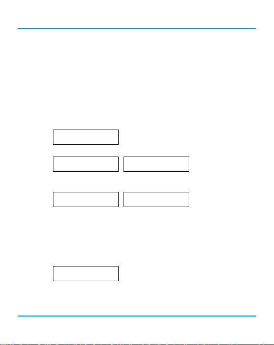
The LCD display can display up to 2 lines of 16 characters. It is backlit green with black text. The
backlight can be turned o , but in normal operation, as con gured from the factory, the display
is backlit. After warm up and upon normal operation, the display will show the current gas level
reading for each channel that it has been con gured.
22 © 2019 All rights reserved. Data subject to change without notice.
Page 23
Rev. A | 2019.07 cGas Detector Digital Transmitter - Operation Manual
Pressing the UP or DOWN button allows you to scroll through a series of information screens
showing the model name, serial number and rmware version; the communication type, ID
and baud rate, the gas type and AD counts; the channel number, gas type and gas level and the
temperature and relative humidity levels (if option is installed).
6.3.1 Adjust Display Brightness
The brightness of the display and the information displayed can be changed as per your preference.
From the main display, press ENTER.
Enter passcode 1014 using the UP button and ENTER button.
Enter Password
1014
Press ENTER to access the Display Menu.
DisplayMenu
Press Enter
Brightness
100
Press ENTER. Use the UP button to change the numeric value. Move to the next digit by pressing
ENTER. When nished, press ENTER to con rm and Exit.
Brightness
>050
Confirm?
50
N
>Y
NOTE: You cannot enter a number higher than 100. Entering a value of 000 turns the backlight o
completely. With ambient light the text can still be read on the display.
6.3.2 Display Con gurations
The default display set from the factory is normal mode which displays the gas type, gas reading
and gas units for each con gured channel.
CO
NO2
00PPM
PPM
The information can be reduced to just the gas type by changing the setting to the minimal mode
display.
© 2019 All rights reserved. Data subject to change without notice. 23
Page 24

cGas Detector Digital Transmitter - Operation Manual Rev. A | 2019.07
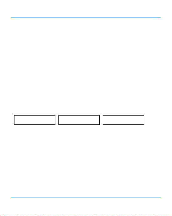
********-CO-*********
********-NO2-********
From the main display, press ENTER.
Enter passcode 1014 using the UP button and ENTER button.
Enter Password
1014
Press ENTER to access the Display Menu.
DisplayMenu
Press ENTER. Use the UP button to change the display type and press ENTER to save and Exit.
Press Enter
Display Type
>Minimal
Display Type
Normal
6.3.3 Display or Hide Line 1 and/or 2
The display can show a maximum of two lines of data. Choose what you want to see on line 1 and
line 2 from four available options.
From the main display, press ENTER.
Enter passcode 1014 using the UP button and ENTER button.
Enter Password
1014
Press ENTER to access the Basic Menu.
Display Menu
Press Enter
Press the UP button until you see Display Line 1 (or Display Line 2).
Display Line 1
>CO
Press ENTER. Using the UP or DOWN buttons, scroll through the display lines to choose from:
• Gas Type (ie. CO)
• Gas Type (ie. NO2)
24 © 2019 All rights reserved. Data subject to change without notice.
Page 25
Rev. A | 2019.07 cGas Detector Digital Transmitter - Operation Manual
• Temp + Humidity (if installed)
• O
The factory default is to display the gas types for the sensors installed. If only one gas sensor is
installed, Display Line 2 will show the Temp + Humidity (if installed) or it will be blank.
NOTE: The Temp + Humidity option is only available with CO and CO2 gas sensors, or by itself.
6.4 Alarm Status, Fault Detection and Communication
Failure Noti cations
If a channel is in alarm, the following letters will be displayed at the end of the line for that
channel.
• low for low alarm
• mid for mid alarm
• high for High alarm
CO
NO2
0.7
0
PPM
CO
low
NO2
The cGas Detector has built in fault detection, and in the event of a problem with the measurement
circuitry the transmitter will indicate a fault condition on the display. Normal operation will resume
once the fault condition has been corrected.
NOTE: To ensure safe operation, monthly bump tests should be done. A damaged solid state or
catalytic sensor will go open circuit and a dead or damaged electrochemical sensor will usually
appear to the transmitter as a zero gas reading. Both instances will cause an incorrect reading
during a bump test and create a fail indication during calibration.
NOTE: If a question mark ? is displayed then the system is in a minor fault and a re-zeroing is
recommended.
© 2019 All rights reserved. Data subject to change without notice. 25
1.0
0
PPM
mid
CO
NO2
1.5
0
PPM
high
Page 26

cGas Detector Digital Transmitter - Operation Manual Rev. A | 2019.07
If there is a communication failure between the cGas Detector and the controller or BAS, the screen
will display COMM at the end of the line.
CO
NO2
00COMM
COMM
For a list of Fault Codes, refer to Section 12 Troubleshooting.
6.5 Setting Channel Alarm Setpoints, Direction and
Hysteresis
The cGas Detector is con gurable as a one or two channel gas detector and each channel can be
con gured with LOW, MID and HIGH gas alarm setpoints in an ascending or descending direction.
The number entered as the setpoint is the exact number/level of gas concentration at which the
device will indicate an alarm condition and trigger a predetermined response from the controller
or control panel. The alarm set points can be changed at any time and do not require a calibration
before, during or after changing them.
NOTE: The cGas Detector DOES NOT HAVE an internal alarm. Gas readings are sent to
the BAS or DDC and if the readings hit an alarm setpoint the BAS or DDC will trigger
whatever type of alarm device or emergency protocol it has been con gured to trigger.
Almost all installations will use the factory default alarm setpoints. Default setpoints are as follows:
SENSO R GAS TY PE
STANDAR D
RANGE
Carbon Dioxide (CO2) 0 - 2,000 ppm 800 ppm 1,000 ppm 1,200 ppm
Carbon Dioxide (CO2) 0 - 5.0% vol 0.15% vol 0.20% vol 0.50% vol
Carbon Monoxide (CO) 0 - 200 ppm 25 ppm 50 ppm 100 ppm
Nitrogen Dioxide (NO2) 0 - 10 ppm 0.7 ppm 1.0 ppm 1.5 ppm
LOW
ALAR M
MID
ALAR M
HIGH
ALAR M
26 © 2019 All rights reserved. Data subject to change without notice.
Page 27

Rev. A | 2019.07 cGas Detector Digital Transmitter - Operation Manual
Combustibles (catalytic) 0 - 100% LEL 10% LEL 15% LEL 20% LEL
For a complete list of all sensors please go to:
https://www.critical-environment.com/support/faq/suggested-alarm-setpoints
An Ascending alarm is used when monitoring a gas that becomes hazardous in increasing quantity.
The normal/safe gas level is below the alarm setpoint and when the gas level increases, reaching
and exceeding the alarm setpoint, the alarm is tripped.
A Descending alarm is used when monitoring a gas that becomes hazardous in decreasing quantity,
such as oxygen. The normal gas level for oxygen is above the alarm setpoint so if the oxygen level
starts to deplete and reaches/goes below the alarm setpoint, the alarm will trip. You can set a
hysteresis value that will be common for all alarm setpoints on that channel.
Hysteresis is the di erence between the ON point and OFF point of the alarm and the value entered
will determine at what gas concentration the alarm will stop. If the alarm setpoint is 100 ppm and
the hysteresis is 5 ppm, when the gas concentration reaches or exceeds 100 ppm, the alarm will
come on. The alarm will stay on until the gas concentration reduces to 95 ppm (5 ppm below the
alarm setpoint).
The purpose of hysteresis is to prevent the alarm from chattering on and o repetitively if the gas
uctuates just above and just below 100 ppm, which would happen if the hysteresis is set to 0.
Likewise, if the device triggers relays, repetitive turning on and o could cause them to burn out.
From the main display, press ENTER.
Enter passcode 2012 using the UP button and ENTER button.
Enter Password
2012
© 2019 All rights reserved. Data subject to change without notice. 27
Page 28
cGas Detector Digital Transmitter - Operation Manual Rev. A | 2019.07
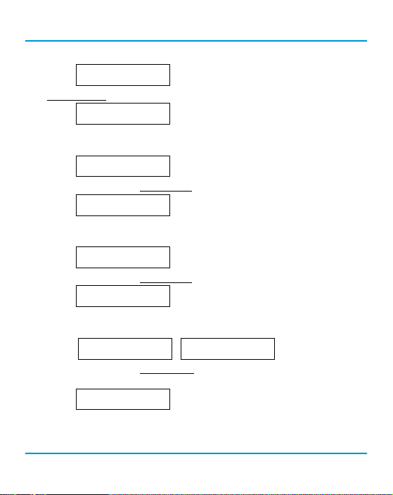
Press ENTER to access the Alarms Menu.
Alarms Menu
Press Enter
In the Selected Channel menu, con rm the correct channel is showing.
Selected Channel
CO
If you want to choose a di erent channel, press Enter and use the UP button to scroll
to the next channel. Press ENTER and continue.
Selected Channel
>NO2
Press the UP button until you see Selected Alarm, con rm the correct alarm level is showing.
Selected Alarm
Low Alarm
If you want to choose a di erent alarm level (ie. Mid or High), press Enter and use
the UP button to scroll to the next alarm level. Press ENTER and continue.
Selected Alarm
Press the Up button until you see Alarm Setpoint, con rm the desired number is showing.
>Mid Alarm
Alarm Setpoint
25 PPM
If you want to enter a di erent alarm setpoint, press Enter and use the UP and ENTER
buttons to change the number. Press ENTER to con rm and continue.
Alarm Setpoint
>050 PPM
Confirm?
>50 PPM
N
>Y
Press the Up button until you see Alarm Direction, con rm the correct direction (ascending or
descending) is showing.
Alarm Direction
ASCENDING
If you want to change the direction, press Enter and use the UP button to scroll to the
next value. Press ENTER to continue.
28 © 2019 All rights reserved. Data subject to change without notice.
Page 29
Rev. A | 2019.07 cGas Detector Digital Transmitter - Operation Manual
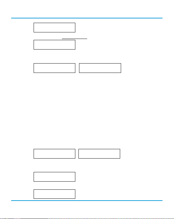
Alarm Direction
>DESCENDING
Press the Up button until you see Alarm Hysteresis, con rm the desired value is showing.
Alarm Hysteresis
005 PPM CO
If you want to change the value, press Enter and use the UP and ENTER buttons to
change the value. Press ENTER to con rm and continue.
Alarm Hysteresis
>010 PPM CO
Confirm?
>10 PPM
N
>Y
6.6 Enable / Disable Channels
This setting allows you to enable or disable the channel(s) that are already con gured in the device.
If the device has one channel, you can enable or disable that one channel. If the devices has two
channels you can independently enable or disable each channel. You may also hide the lines of
disabled channels. Refer to Section 6.3.3 Display or Hide Line 1 and/or 2.
NOTE: If the device has one channel, enabling the second channel does not add an operational
channel to the device.
A disabled channel acts as if it does not exist, it will not show gas readings. A disabled channel will
show on the normal display with four dashes in the middle of the line:
From the main display, press ENTER.
Enter passcode 3022 using the UP button and ENTER button.
Press ENTER to access the Con g Menu.
© 2019 All rights reserved. Data subject to change without notice. 29
CO
NO2
Enter Password
3022
Config Menu
Press Enter
---- PPM
0 PPM
CO
76.4 degF
0 PPM
----%RH
Page 30

cGas Detector Digital Transmitter - Operation Manual Rev. A | 2019.07
In the Selected Channel menu, con rm the correct channel is showing.
Selected Channel
CH1 CO
If you want to choose a di erent channel, press ENTER and use the UP button to
scroll to the next value. Press ENTER and continue.
Selected Channel
>Temperature
The list to choose from will depend on included sensors and options:
• CH1
• CH2
• Temperature (if installed)
• Humidity (if installed)
Press the UP button to nd Channel En/Dis. To make a change, press ENTER and then the UP button
to choose Enable or Disable and press ENTER to select and Exit.
ChannelEn/Dis
Enabled
CO
----degF
6.7 Change Units (
o
ChannelEn/Dis
>Disable
0 PPM
38%RH
C or oF) of Temperature Readings
NOTE: This menu item only applies if the cGas Detector has the -RHT option installed.
You can change the factory con gured temperature unit type from Celsius to Fahrenheit (or vice
versa) very easily.
From the main display, press ENTER.
Enter passcode 3032 using the UP button and ENTER button.
Enter Password
3032
Press ENTER to access the Calibrate Menu.
30 © 2019 All rights reserved. Data subject to change without notice.
Page 31
Rev. A | 2019.07 cGas Detector Digital Transmitter - Operation Manual
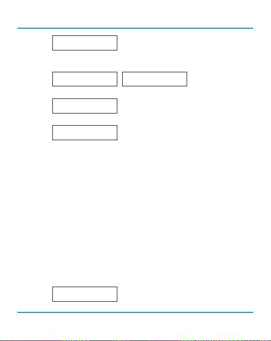
Calibrate Menu
Press Enter
In the Selected Channel menu, if Temperature is not displayed, press ENTER and use the UP button
to scroll to nd Temperature. Press ENTER.
Selected Channel
CO
Selected Channel
>Temperature
Use the UP button to nd Temperature Unit. If you want to change the unit type, press ENTER.
Temperature Unit
Celsius
Press the UP button to choose Fahrenheit press ENTER and ENTER to exit.
Temperature Unit
>Fahrenheit
6.8 Temperature and/or Relative Humidity O set
NOTE: This menu item only applies if the cGas Detector has the -RHT option installed.
NOTE: Depending on the con guration, the device will show the temperature in either Celcius or
Fahrenheit. The units can be changed at any time, refer to Section 6.7 Change Units (degC or degF) of
Temperature Readings.
The temperature and relative humidity sensors come pre-calibrated from the factory. If you nd
that the readings on the cGas Detector are higher or lower than another measurement device, you
can adjust the reading by setting an o set value so the reading is more accurate. The Temperature
o set value is a number of degrees and the Humidity o set value is a percentage, both in either
direction of 0.
From the main display, press ENTER.
Enter passcode 3032 using the UP button and ENTER button.
Enter Password
3032
© 2019 All rights reserved. Data subject to change without notice. 31
Page 32
cGas Detector Digital Transmitter - Operation Manual Rev. A | 2019.07
Press ENTER to access the Calibrate Menu.
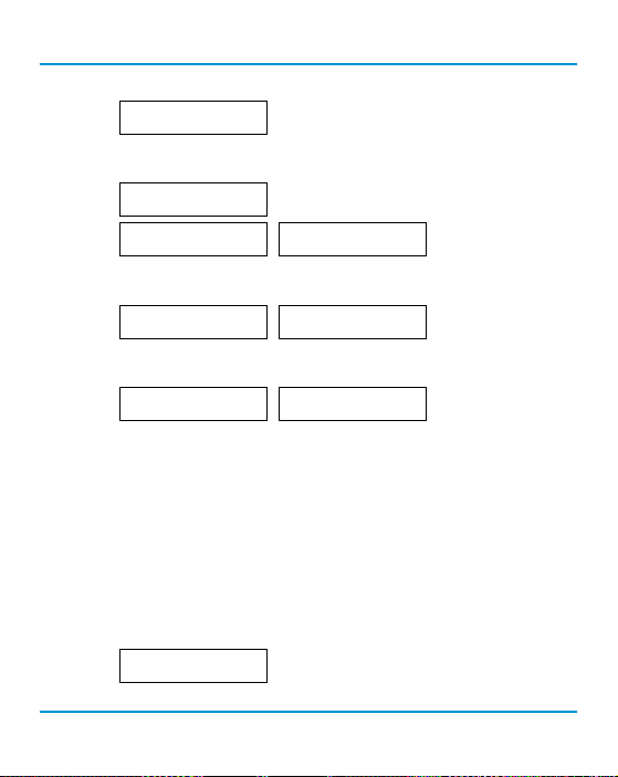
Calibrate Menu
Press Enter
In the Selected Channel menu, if Temperature (or Humidity) is not displayed, press ENTER and use
the UP button to scroll to nd the item you are looking for. Press ENTER.
Selected Channel
CO
Selected Channel
>Temperature
Selected Channel
>Humidity
Use the UP button to nd Temperature Adj (or Humidity Adj). If you want to change the o set value,
press ENTER. Change the o set value using the UP or DOWN and ENTER buttons.
Temperature Adj
>-4.0 degC
Humidity Adj
>+02 %RH
Press ENTER to con rm the value is correct. If you entered the wrong value, press the UP button to
move the cursor to N and press ENTER and reenter the value.
Confirm?
>-4.0 degC
N
>Y
>+2 %RH
Confirm?
N
>Y
6.9 Test Functions
The test functions listed in this menu will depend on the con guration of the individual cGas
Detector. For each gas channel, you can manually enter a gas reading value of your choice (within
the range of the sensor) that will be sent over the digital network to test the connection and
con gured responses between the cGas Detector and the DDC/BAS. You can do the same for relative
humidity and temperature if the -RHT option is installed.
From the main display, press ENTER.
Enter passcode 0001 using the UP button and ENTER button.
Press ENTER to access the Test Menu.
32 © 2019 All rights reserved. Data subject to change without notice.
Enter Password
0001
Page 33
Rev. A | 2019.07 cGas Detector Digital Transmitter - Operation Manual
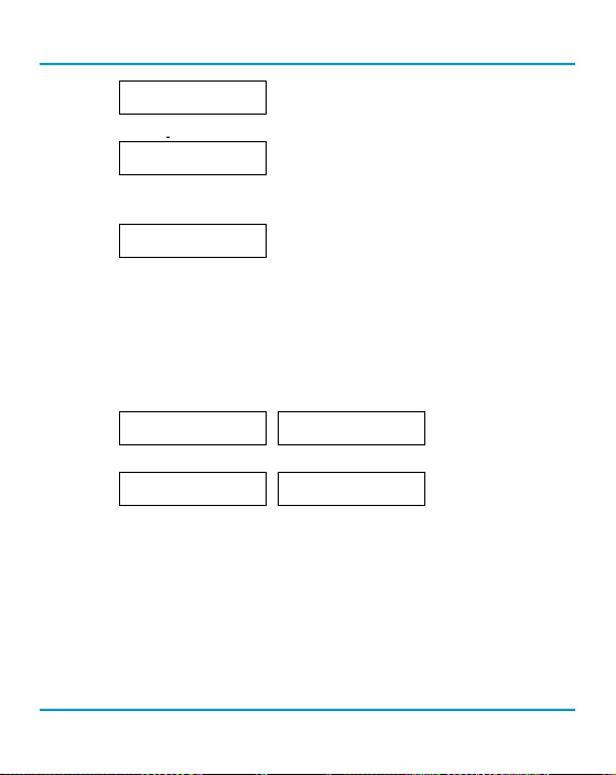
Test Menu
Press Enter
In the Selected Channel menu, con rm the correct channel is showing.
Selected Channel
CO
If you want to choose a di erent channel, press ENTER and use the UP button to
scroll to the next value. Press ENTER and continue.
Selected Channel
>NO2
The list to choose from will depend on included sensors and options:
• Gas Type (ie. CO)
• Gas Type (ie. NO2)
• Temperature
• Humidity
Press the UP button to nd Test Reading. To make a change, press ENTER and then use the UP,
DOWN and ENTER buttons to enter the value.
Test Reading
0 PPM NO2
Test Reading
>10.0 PPM NO2
Press ENTER and then again to Con rm Y.
Confirm?
>10.0 PPM NO2
N
>Y
Test Reading
10.0 PPM NO2
The test will start as soon as you press ENTER to con rm and will remain in the test
mode as long as the Test Reading screen remains untouched. To stop the test, press the UP
or DOWN button. Test another reading value or press ENTER to Exit.
© 2019 All rights reserved. Data subject to change without notice. 33
Page 34

cGas Detector Digital Transmitter - Operation Manual Rev. A | 2019.07
7 MODBUS AND BACNET CONFIGURATION
The cGas Detector can be changed from Modbus® to BACnet® or vice versa in the eld.
7.1 Changing Communication Type (Modbus®/
BACnet®) in the Field
When the communication type is changed, the device will reset, which will brie y interrupt
communications on the network it is connected to.
From the main display, press ENTER.
Enter passcode 1001 using the UP button and ENTER button.
Press ENTER to access the Basic Menu.
Press ENTER. Use the UP or DOWN buttons to choose MODBUS or BACNET or Cancel. Press ENTER. If
you have changed the communication type, the device will display Reset Device.
Press ENTER and the cGas Detector will power o and on. This will cause a brief interruption in
communications if the cGas Detector is on a network.
NOTE: If you change the Comm Type, make sure you make the necessary changes to the
corresponding MAC, Baud and Instance ID as appropriate. Refer to the following Sections 7.2
Con guring Modbus® Settings or 7.3 Con guring BACnet® Settings.
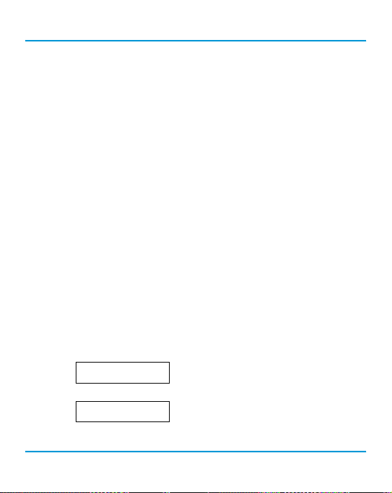
Enter Password
1001
Basic Menu
Press Enter
Comm Type
>BACNET
Comm Type
MODBUS
Reset Device
34 © 2019 All rights reserved. Data subject to change without notice.
Page 35
Rev. A | 2019.07 cGas Detector Digital Transmitter - Operation Manual
7.2 Con guring Modbus® Settings
If a complete system (controller with digital transmitters and peripherals) is ordered from the
factory, it will be shipped precon gured with the appropriate Modbus® settings.
Factory Default Modbus® Settings
• Modbus® ID = 100 (default, con gurable)
• Baud rate =19,200 (default, con gurable)
• Data bits = 8
• Stop bits = 1
• Parity = none
If you are not using the cGas Detector with a CETCI controller but are adding it to an existing system
the transmitters may require changes to the default Modbus® settings in order for communication
to be successful between devices. Make sure your network connection is complete, the network
termination switches are set appropriately and all the devices are con gured with the same baud
rate, character format, etc. Each device must have its own unique Modbus® ID.
7.2.1 Change Modbus® MAC Address
All devices on the same network must have a unique Modbus ID. The range of numbers that can be
used as a Modbus® MAC address is 100 to 255.
From the main display, press ENTER.
Enter passcode 1001 using the UP button and ENTER button.
Press ENTER to access the Basic Menu.
The Comm Type displayed should be MODBUS. Press the UP button until you see Comm MAC.
Enter Password
1001
Basic Menu
Press Enter
© 2019 All rights reserved. Data subject to change without notice. 35
Page 36
cGas Detector Digital Transmitter - Operation Manual Rev. A | 2019.07
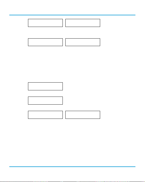
Comm Type
MODBUS
Comm MAC
000
Press ENTER. Use the UP or DOWN buttons to change the numeric value. Move to the next digit by
pressing ENTER. When nished, press ENTER to con rm and again to Exit.
Comm MAC
>101
Confirm?
>101
N
>Y
7.2.2 Change Modbus® Baud Rate
All devices on the same network must have the same baud rate. The default Modbus® baud rate for
all CETCI Modbus® devices is 19,200.
From the main display, press ENTER.
Enter passcode 1001 using the UP button and ENTER button.
Enter Password
1001
Press ENTER to access the Basic Menu.
Basic Menu
Press Enter
The Comm Type should be Modbus. Press the UP button until you see Comm Baud.
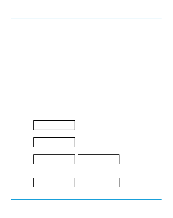
Comm Type
MODBUS
Comm Baud
19,200
Press ENTER. Use the UP or DOWN buttons to scroll through the baud rates to choose from:
• 9,600
• 14,400
• 19,200 (default, con gurable)
• 38,400
• 57,600
• 76,800
• 115,200
Select the preferred baud rate by pressing ENTER to save. Press the UP button and ENTER to Exit.
36 © 2019 All rights reserved. Data subject to change without notice.
Page 37
Rev. A | 2019.07 cGas Detector Digital Transmitter - Operation Manual
7.2.3 Modbus® Holding Registers
If you have speci c requirements, have any questions or require clari cation about the Modbus®
holding registers, please contact CETCI for assistance.
7.3 Con guring BACnet® Settings
The cGas Detector can be con gured with BACnet® output to communicate with a BAS, DDC or
similar control panel.
7.3.1 Change BACnet® MAC Address
The factory set default BACnet® MAC address is 100. The MAC ID along with the Instance ID make up
the complete ID for the device. Each device requires a unique ID in order to communicate with the
BAS / DDC. A MAC address should be set for each digital cGas Detector during installation.
From the main display, press ENTER.
Enter passcode 1001 using the UP button and ENTER button.
Press ENTER to access the Basic Menu.
The Comm Type should be BACnet. Press the UP button until you see Comm MAC.
Press ENTER. Use the UP button to change the numeric value. Move to the next digit by pressing
ENTER. When nished, press ENTER to con rm and Exit.
Enter Password
1001
Basic Menu
Press Enter
Comm Type
BACnet
Comm MAC
>111
Comm MAC
100
Confirm?
>111
N
>Y
© 2019 All rights reserved. Data subject to change without notice. 37
Page 38
cGas Detector Digital Transmitter - Operation Manual Rev. A | 2019.07
7.3.2 Change BACnet® Instance ID
Every device on a BACnet® network must have a unique Instance ID. An Instance ID is the Vendor ID
(or Base ID) followed by the device’s MAC address. CETCI’s Vendor ID is 270. If the device’s MAC ID is
100, then the Instance ID would be 270100.
From the main display, press ENTER.
Enter passcode 1001 using the UP button and ENTER button.
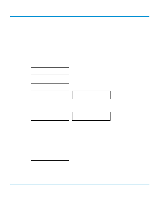
Enter Password
1001
Press ENTER to access the Basic Menu.
Basic Menu
Press Enter
The Comm Type should be BACnet. Press the UP button until you see Instance ID.
Comm Type
BACnet
Instance ID
270100
Press ENTER. Use the UP button to enter the numeric value. Move to the next digit by pressing
ENTER. When nished, press ENTER to con rm and Exit.
Instance ID
>0270111
Confirm?
>270111
N
>Y
7.3.3 Change BACnet® Baud Rate
All devices on the same BACnet® network must have the same baud rate. The default BACnet® baud
rate is 76,800.
From the main display, press ENTER.
Enter passcode 1001 using the UP button and ENTER button.
Enter Password
1001
Press ENTER to access the Basic Menu.
38 © 2019 All rights reserved. Data subject to change without notice.
Page 39
Rev. A | 2019.07 cGas Detector Digital Transmitter - Operation Manual
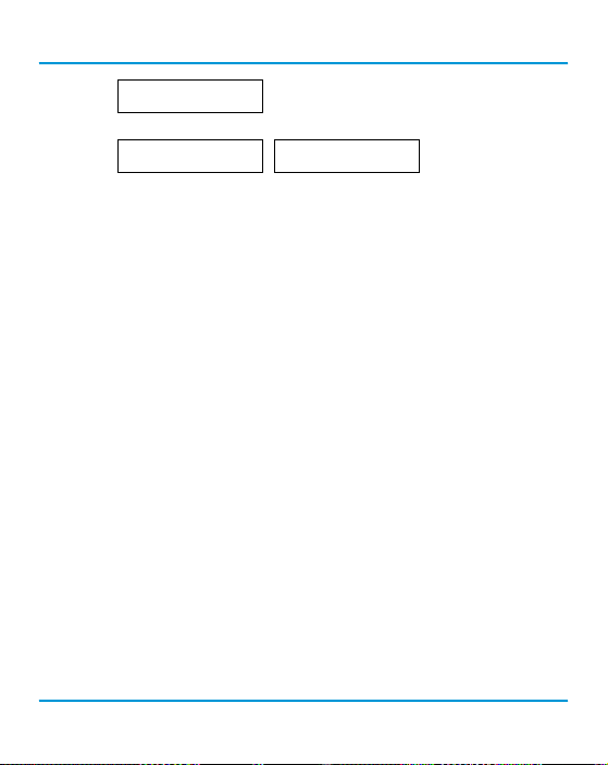
Basic Menu
Press Enter
The Comm Type should be BACnet. Press the UP button until you see Comm Baud.
Comm Type
BACnet
Comm Baud
19200
Press ENTER. Using the UP or DOWN buttons, scroll through the baud rates to choose from:
• 9,600
• 14,400
• 19,200
• 38,400
• 57,600
• 76,800 (default, con gurable)
• 115,200
Select the preferred baud rate by pressing ENTER to save. Press the UP button and then ENTER to
Exit.
7.3.4 BACnet® PICS Information
Critical Environment Technologies Canada Inc. (CETCI) has been granted the BACnet® Testing
Laboratories (BTL) certi cation for the CGAS Detector Family upon passing the BTL requirements for
the BACnet® Smart Actuator (B-SA) designation.
To follow is the BACnet® Protocol Implementation Conformance Statement (PICS) information that
can also be found on the BACnet® International website at http://www.bacnetinternational.org
Date: April 2019
Vendor Name: Critical Environment Technologies Canada Inc.
Product Name: CGAS Detector Family
Product Model Numbers: CGAS-D, CGAS-DP, CGAS-SC
Application Software Version: 1.1
Firmware Revision: 3.7.12.0
© 2019 All rights reserved. Data subject to change without notice. 39
Page 40

cGas Detector Digital Transmitter - Operation Manual Rev. A | 2019.07
BACnet® Protocol Version/Revision: 14
Product Description:
The CGAS Detector product line is a group of customizable two channel gas detectors featuring
a range a possible gases and options. The various gases are added to the device using plug and
play “smar t sensor” boards, which attach to the main board within the enclosure. The main board
handles communication back to a controller or building management system via eld con gurable
Modbus® RTU or BACnet® MS/TP.
BACnet® Standardized Device Pro le (Annex L):
*BACnet® Operator Workstation (B-OWS)
*BACnet® Building Controller (B-BC)
*BACnet® Advanced Application Controller (B-AAC)
*BACnet® Application Speci c Controller (B-ASC)
*BACnet® Smart Sensor (B-SS)
RBACnet® Smart Actuator (B-SA)
List all BACnet® Interoperability Building Blocks Supported (Annex K):
BIBB Service Responds to
DS-RP-B
DS-WP-B
DM-DDB-B
DM-DOB-B
Segment Capability:
Segment requests supported Window Size 480
Segment requests supported Window Size 480
ReadProperty-B
WriteProperty-B
Dynamic Object Device Binding-B
Dynamic Object Binding-B
X
X
X
X
40 © 2019 All rights reserved. Data subject to change without notice.
Page 41

Rev. A | 2019.07 cGas Detector Digital Transmitter - Operation Manual
Standard Object Types Supported:
An object type is supported if it may be present in the device. For each standard Object Type
supported provide the following data:
1. Whether objects of this type are dynamically creatable using the CreateObject service
2. Whether objects of this type are dynamically deletable using the DeleteObject ser vice
3. List of the optional properties suppor ted
4. List of all properties that are writable where not otherwise required by this standard
5. List of proprietary properties and for each its propert y identi er, datatype, and meaning
6. List of any property range restrictions
NOTE: None of the object types listed in this section is dynamically creatable or dynamically
deletable.
NOTE: The BACnet conformance codes are as follows:
O - Optional (may be required under some conditions)
R - Required, but not required to be writable (may be required to be writable
under some conditions)
W - Not only required, but also required to be writable
The following codes are used in this document to describe how the properties are implemented:
R/W Read/write
R/O Read-only
R/O=value Implemented as a read-only with the indicated value
© 2019 All rights reserved. Data subject to change without notice. 41
Page 42

cGas Detector Digital Transmitter - Operation Manual Rev. A | 2019.07
Device Object
Property
Object_Identi er
Object_Name
Object_Type
System_Status
Vendor_Name
Vendor_Identi er
Model_Name
Firmware_Revision
Application_Software_Version
Location
Protocol_Version
Protocol_Revision
Protocol_Services_Supported
Protocol_Object_Types_Supported
Object_List
Max_APDU_Length_Accepted
Segmentation_Supported
APDU_Timeout
Number_Of_APDU_Retries
Max_Master
Device_Address_Binding
Data_Base_Revision
Max-Info-Frames
BACnet®
Conf Code
R
R
R
R
R
R
R
R
R
O
R
R
R
R
R
R
R
R
R
O
R
R
O
Implementation
R/O
R/O
R/O=”device”
R/O=”operational”
R/O
R/O
R/O
R/O
R/O
R/W
R/O=1
R/O=14
R/O
R/O
R/O
R/O=480
R/O=”none”
R/W=7000
R/W=1
R/O=127
R/O=empty list
R/O
R/O=1
42 © 2019 All rights reserved. Data subject to change without notice.
Page 43

Rev. A | 2019.07 cGas Detector Digital Transmitter - Operation Manual
Analog Input
Property
Object_Identi er
Object_Name
Object_Type
Present_Value
Status_Flags
Event_State
Out_Of_Service
Units
Property_List
Description
BACnet®
Conf Code
R
R
R
R
R
R
R
R
R
O
Implementation
R/O
R/O
R/O=”analog input”
R/O
R/O
R/O=”normal”
R/O=FALSE
R/O
R/O
R/W
Analog Output
Property
Object_Identi er
Object_Name
Object_Type
Present_Value
Status_Flags
Event_State
Out_Of_Service
Units
Priority_Array
Relinquish_Default
BACnet®
Conf Code
R
R
R
W
R
R
R
R
R
R
Implementation
R/O
R/O
R/O=”analog-output”
R/W
R/O=”all normal”
R/O=”normal”
R/O=FALSE
R/O
R/O
R/W
© 2019 All rights reserved. Data subject to change without notice. 43
Page 44

cGas Detector Digital Transmitter - Operation Manual Rev. A | 2019.07
Property_List
Description
Binary Output
Property
Object_Identi er
Object_Name
Object_Type
Present_Value
Status_Flags
Event_State
Out_Of_Service
Polarity
Priority_Array
Relinquish_Default
Description
Data Link Layer Options:
R
O
BACnet®
Conf Code
R
R
R
W
R
R
R
R
R
R
O
R/O
R/W
Implementation
R/O
R/O
R/O=”binary-output”
R/W
R/O=”all normal”
R/O=”normal”
R/O=FALSE
R/W
R/O
R/O
R/W
*BACnet® IP, (Annex J)
*BACnet® IP, (Annex J), Foreign Device
*ISO 8802-3, Ethernet (Clause 7)
*ANSI/ATA 878.1, 2.5 Mb. ARCNET (Clause 8)
*ANSI/ATA 878.1, RS-485 ARCNET (Clause 8), baud rate(s) ___________
RMS/TP Master Node (Clause 9), baud rate(s): 9600, 19200, 38400, 57600, 76800, 115200
*MS/TP Slave (Clause 9), baud rate(s):
*Point-To-Point, EIA 232 (Clause 10), baud rate(s):
*Point-To-Point, modem, (Clause 10), baud rate(s):
*LonTalk, (Clause 11), medium: __________
*Other:
44 © 2019 All rights reserved. Data subject to change without notice.
Page 45

Rev. A | 2019.07 cGas Detector Digital Transmitter - Operation Manual
Device Address Binding:
Is static device binding supported? (This is currently necessary for two-way communication with
MS/TP slaves and certain other devices.) RYes *No
Networking Options:
*Router, Clause 6 - List all routing con gurations, e.g., ARCNET-Ethernet,
Ethernet-MS/TP, etc.
*Annex H, BACnet Tunneling Router over IP
*BACnet®/IP Broadcast Management Device (BBMD)
Does the BBMD support registrations by Foreign Devices? *Yes RNo
Character Sets Supported:
Indicating support for multiple character sets does not imply that they can all be supported
simultaneously.
RANSI X3.4 *IBM™/Microsoft™ DBCS *ISO 8859-1 *ISO 10646 (UTF-8)
*JIS C 6226 *ISO 10646 (UCS-2) *ISO 10646 (UCS-4)
Network Security Options:
RNon-secure Device - is capable of operating without BACnet® Network Security
BACnet® Communications Defaults:
Baud rate =78,800 (default, con gurable)
Base address = 270 (default, con gurable)
MAC address = 100 (default, con gurable)
Parity = no parity
Stop bits = 1
Data bits = 8
© 2019 All rights reserved. Data subject to change without notice. 45
Page 46

cGas Detector Digital Transmitter - Operation Manual Rev. A | 2019.07
If you have speci c requirements, have any questions or require clari cation about the BACnet®
PICS information, please contact CETCI for assistance.
8 PLUG & PLAY SMART SENSOR REPLACEMENT
A sensor will need to be replaced when it does not have enough sensitivity to respond to a bump
test or it repeatedly fails calibration. Similarly, the sensor may need to be replaced if the application
requirements change and a di erent gas needs to be monitored.
A Plug & Play Smart Sensor Board is a sensor that is fastened to a small circuit board with a memory
chip that contains the sensor’s calibration and con guration information. When a replacement
smart sensor board or a brand new gas smart sensor board is installed, the information it contains
must be written to the main circuit board.
8.1 How to Replace or Add a New Smart Sensor Board
Smart board replacement sensors arrive pre-calibrated and factory con gured. After you physically
replace the smart sensor board, you have to Read the data stored in the new sensor board up to
the main board, overwriting the old sensor’s calibration information. After an appropriate warm up
period (24 hours), you may want to do a bump test to con rm the response from the sensor.
Power OFF the unit during the physical replacement of the sensor boards.
With the door open, look at the smart sensor boards, CH1 is the socket on the left side and CH2 is
the socket on the right side.
If replacing an existing sensor, unscrew the smart sensor board you want to replace and gently pull
it out of the socket. Insert the new smart sensor board and screw it in place.
If adding a new smart sensor to an empty socket, make sure to remove the perforated foam circle in
the sensor cavity, then insert the smart board and screw it in place.
46 © 2019 All rights reserved. Data subject to change without notice.
Page 47
Rev. A | 2019.07 cGas Detector Digital Transmitter - Operation Manual
NOTE: If the second sensor is a CO sensor smart board, it will be shipped with a small plastic short
sensor adapter. After removing the foam, insert the short sensor adapter before plugging the CO
smart sensor board into the socket.
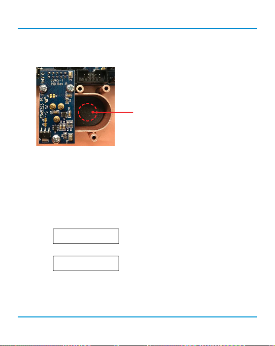
When installing a second smart sensor
after initially ordering a single smart
sensor model, you will need to remove the
center circular cut out of the foam in the
second sensor vent area before installing
the smart board.
8.2 Read From Sensor
During this process, the main board Reads the calibration and con guration information stored
in the smart sensor board and saves the information, overwriting the existing calibration and
con guration information for that sensor in the main board.
With the unit powered ON, from the main display, press ENTER.
Enter passcode 3022 using the UP button and ENTER buttons.
Press ENTER to access the Con g Menu.
In the Selected Channel menu, con rm the desired channel is showing. If you want to choose a
di erent channel, press ENTER and use the UP button to scroll to the next value. Press ENTER and
continue.
Enter Password
3022
Config Menu
Press Enter
© 2019 All rights reserved. Data subject to change without notice. 47
Page 48

cGas Detector Digital Transmitter - Operation Manual Rev. A | 2019.07
Selected Channel
CH1 CO
Press the UP button to nd Read From Sensor. Press ENTER.
Read from Sensor
CH1 (Left)
Read from Sensor
>YES
Press the UP button to change from NO to YES and press ENTER to select. The system will Read the
new calibration information to the main board. Press ENTER to exit.
NOTE: Make sure you are reading from the correct sensor - left vs right.
8.3 Write to Sensor
This process forces a Write of the calibration and con guration information stored in the main board
to the smart board sensor. Every time a change is made on the cGas Detector, the main circuit board
Writes the change to the smart sensor board automatically. However, there may be instances when
you may want to force Write the changes to the smart sensor board, such as if the memory of the
smart sensor board gets corrupted.
From the main display, press ENTER.
Enter passcode 3022 using the UP button and ENTER buttons.
Press ENTER to access the Con g Menu.
In the Selected Channel menu, con rm the desired channel is showing.
If you want to choose a di erent channel, press ENTER and use the UP button to
scroll to the next value. Press ENTER and continue.
Enter Password
3022
Config Menu
Press Enter
Selected Channel
CH1 CO
48 © 2019 All rights reserved. Data subject to change without notice.
Page 49
Rev. A | 2019.07 cGas Detector Digital Transmitter - Operation Manual
Selected Channel
>CH2 NO2
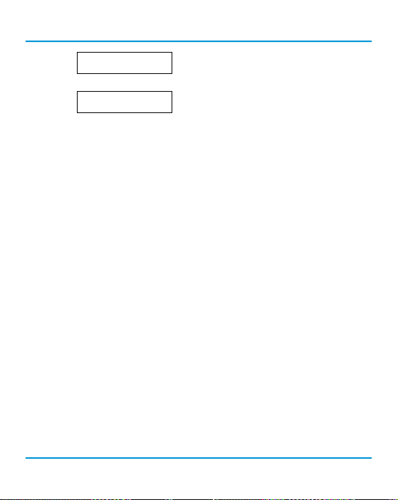
Press the UP button to nd Write to Sensor. Press ENTER.
Write to Sensor
CH2 (right)
Press the UP button to change from NO to YES and press ENTER to select. The system will Write the
sensor con guration information to the smart sensor board. Press ENTER to exit. Repeat for the
second channel if required.
NOTE: Make sure you are writing to the correct sensor - left vs right.
9 CALIBRATION
9.1 Calibration Speci cations
9.1.1 Gas
Calibration span gas cylinders should have at least ± 5% accuracy and have a current date stamp.
Gas generators should have a current dated cell installed.
Service personnel should ow zero emissions air or 20.9% volume O2 (scrubbed of hydrocarbons)
before attempting to null adjust (zero) toxic gas sensors. In some cases nitrogen (N2) can be
substituted for zero air when null adjusting electrochemical sensors. Contact CETCI for clari cation.
The type of gas mixture, how old the gas is and what temperature it has been stored at will a ect
repeatability during eld calibration.
IMPORTANT NOTES:
• Ox ygen sensors require 99.9% nitrogen (N2) for a true zero. We recommend doing the span
rst, followed by zeroing.
• Carbon dioxide sensors require 99.9% nitrogen (N2) for a true zero. If the cGas Detector has
a splash guard you will need to ow the nitrogen for approximately 4 minutes BEFORE you
© 2019 All rights reserved. Data subject to change without notice. 49
Page 50

cGas Detector Digital Transmitter - Operation Manual Rev. A | 2019.07
enter the Calibrate Zero menu. Same when owing CO2 calibration gas, ow for 4 minutes
BEFORE you enter the Calibrate Span menu.
• Catalytic sensors require oxygen to work and thus the user MUST ow clean air or oxygen to
obtain a true zero and the span gas must have “air” balance, not N2 balance.
9.1.2 Regulators & Flow
Calibration gases that are lighter than or the same weight as air (CO, O2, etc.) should be owed at
0.5 LPM. Gases heavier than air (NO2, etc.) should be owed between 0.5 and 1.0 LPM. Fixed ow
regulators provide more accuracy.
9.1.3 Adapters
The proper calibration adapter should be utilized to allow the gas to properly di use around the
sensor. The calibration adapter plug for a cGas Detector with an internal sensor without a splash
guard is part number CET-7000-CAP. For a cGas Detector with a splash guard, use part number
CET-4700-SCC or use the Cal Clip hands free adapter, part number CET-SGC.
9.1.4 Calibration Frequency
• Parking garage detectors: Once every 12 months
• OHS applications: Once every 6 months (OHS: Occupational Health & Safety)
• For best performance and to meet published speci cations: once every six months
NOTE: A calibration label should be applied after every calibration to con rm work performed and
the date it was con rmed. If a controller is involved, the alarm set points should be indicated on a
label on the front door of the enclosure so anyone working in the environment can be aware.
Equipment: Calibration Kit, Calibration gases
Users can order the calibration kit, calibration accessories and / or gases from any CETCI authorized
distributor or you can supply your own gas and equipment as long as the gas meets the minimum
50 © 2019 All rights reserved. Data subject to change without notice.
Page 51

Rev. A | 2019.07 cGas Detector Digital Transmitter - Operation Manual
speci cations. CETCI does not ship gas cylinders outside of Canada.
9.1.5 Gas Testing Frequency (Bump Testing)
For the purpose of safety in OHS applications, sensors should be gas tested (bump tested) once
every month to con rm response and alarm activation.
9.1.6 Sticky Gases
Sticky gases, such as Ozone (O3), Chlorine (Cl2) Chlorine Dioxide (ClO2), Hydrogen Chloride (HCl),
Hydrogen Cyanide (HCN), Nitrogen Dioxide (NO2) and Phosphine (PH3) adhere to surfaces such
as tubing and splash guards. The cGas Detector can be ordered with a special splash guard if
con gured with a sticky gas sensor. When calibrating with sticky gases we suggest using Te on
lined tubing so the gas doesn’t adhere to the tubing, reducing the concentration of the ow of gas.
Also keep the length of the tubing as short as possible, no more than 0.91 to 1.22 m / 3 - 4 ft so the
gas ow concentration doesn’t lessen over the distance from the gas cylinder to the sensor.
It is also suggested that when calibrating a Chlorine sensor, you use a chlorine gas generator due
to the instability of Chlorine gas in a cylinder and the fact that it is di cult to get accurate readings
from that source.
9.2 Calibrating the Internal Sensor(s)
Calibration has three processes - Set Calibration Gas Value, Span and Zero. The Span and Zero
calibrations can be done in any order. However when calibrating an Oxygen sensor we suggest the
Zero calibration be done before the Span calibration. Refer to Section 9.4 Calibrating an Ox ygen
Sensor. When calibrating a CO2 sensor, ow the nitrogen gas and the span gas for 4 minutes before
entering the Calibrate Zero and Calibrate Span menus.
9.2.1 Set Calibration Gas Value
Check to make sure that the calibration gas value con gured in the device matches the gas
concentration of the calibration gas cylinder you are using. This is especially important if you are
not using the same Cal gas concentration that was used previously to calibrate the device. How
© 2019 All rights reserved. Data subject to change without notice. 51
Page 52
cGas Detector Digital Transmitter - Operation Manual Rev. A | 2019.07
much gas the sensor detects is directly related to the Cal gas setting and the actual concentration of
calibration gas used during calibration.
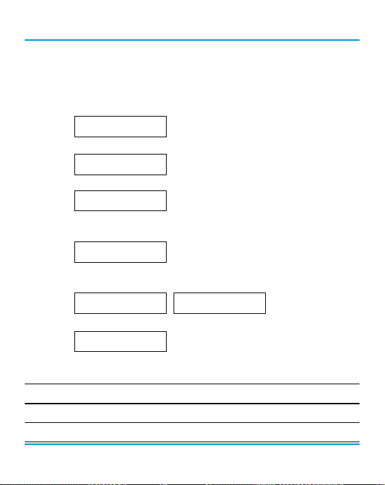
From the main display, press ENTER.
Enter passcode 3032 using the UP button and ENTER button.
Enter Password
3032
Press ENTER to access the Calibrate Menu.
Calibrate Menu
In the Selected Channel menu, con rm the desired channel is showing.
Press Enter
Selected Channel
CO
If you want to choose a di erent channel, press ENTER and use the UP button to
scroll to the next channel. Press ENTER and continue.
Selected Channel
>NO2
Press the UP button to accept the displayed calibration gas value if it is correct. Or press ENTER and
change the value using the UP or DOWN buttons.
Calibration Gas
50 PPM CO
Calibration Gas
>100 PPM CO
When nished pressed ENTER and then ENTER again to con rm and ENTER to exit.
Confirm?
>100 PPM
N
>Y
The factory default calibration gas concentrations are:
SENSO R GAS TY PE CALI BRATION GAS LEVEL*
Carbon Dioxide (CO2) 1000 PPM
Carbon Dioxide (CO2) 1.0 % VOL
52 © 2019 All rights reserved. Data subject to change without notice.
Page 53
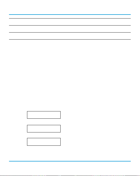
Rev. A | 2019.07 cGas Detector Digital Transmitter - Operation Manual
Carbon Monoxide (CO) 100 PPM
Nitrogen Dioxide (NO2) 5 PPM
Combustibles 20% LEL
* subject to change when required
9.2.2 Zero (Null) Calibration
Before trying to zero toxic gas sensors, zero emissions air or 20.9% volume O2 (scrubbed of
hydrocarbons) should be owed over the sensors. In some cases nitrogen (N2) can be substituted
for zero air when null adjusting electrochemical sensors. Oxygen and CO2 sensors require 99.9%
N2 for a true zero. Catalytic sensors require oxygen to work and thus the user MUST ow clean air
or oxygen to obtain a true zero and the span gas must have “air” balance, not N2 balance. If using
ambient air to zero the gas detector, make sure the environment has clean air or the process could
result in a Zero fault.
NOTE: To exit the Zero Calibration at any time, press ENTER.
From the main display, press ENTER.
Enter passcode 3032 using the UP button and ENTER button.
Enter Password
3032
Press ENTER to access the Calibrate Menu.
Calibrate Menu
In the Selected Channel menu, con rm the desired channel is showing.
Press Enter
Selected Channel
CO
If you want to choose a di erent channel, press ENTER and use the UP button to
scroll to the next channel. Press ENTER and continue.
© 2019 All rights reserved. Data subject to change without notice. 53
Page 54
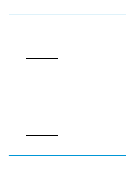
cGas Detector Digital Transmitter - Operation Manual Rev. A | 2019.07
Selected Channel
>NO2
Press the UP button to nd Calibrate Zero.
Calibrate Zero
100 AD
Press ENTER if using ambient air or attach the regulator to the cylinder of zero air, insert the
calibration adapter into the sensor opening on the front of the enclosure door (refer to Section 9.3.1
Calibration Adapter Plug if the adapter will not t). Press ENTER to start the Zero calibration. The
display will show a countdown from 20 seconds.
Zeroing
47AD
Zero Success
56AD
18s
When the process has nished and the Zero calibration was accepted, press ENTER and use the UP
button navigate to Exit and press ENTER to exit. Remove the cylinder of zero gas.
If the Zero calibration was not successful refer to Section 9.3.2 Zero Fault.
9.2.3 Span Calibration
Span calibration is owing a known concentration of the target gas over the sensor to adjust the
output signal to match the gas concentration. It resets the sensor’s electronic circuit against a
known concentration of target gas to correct drift and keep linearity.
NOTE: To exit the Span Calibration at any time, press ENTER.
From the main display, press ENTER.
Enter passcode 3032 using the UP button and ENTER button.
Enter Password
3032
Press ENTER to access the Calibrate Menu.
54 © 2019 All rights reserved. Data subject to change without notice.
Page 55
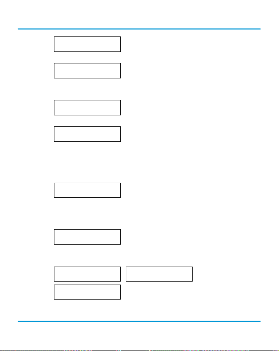
Rev. A | 2019.07 cGas Detector Digital Transmitter - Operation Manual
Calibrate Menu
In the Selected Channel menu, con rm the desired channel is showing.
Press Enter
Selected Channel
CO
If you want to choose a di erent channel, press ENTER and use the UP button to
scroll to the next channel. Press ENTER and continue.
Selected Channel
Use the UP button to nd Calibrate Span. Press ENTER.
>NO2
Calibrate Span
4000 AD
Con rm the span calibration gas level. It is important to make sure that the span gas level value
matches the calibration gas concentration you are using to calibrate the sensor. Press ENTER to
con rm value is correct. (If the value is not correct, press the UP button to move the cursor to N and
press ENTER. Change the cal gas level using the UP and ENTER buttons.)
Confirm CalGas
>100 PPM
N
>Y
Press ENTER to con rm. Attach the regulator to the span gas cylinder and ow the span gas over
the sensor. You have 120 seconds to start owing the gas. If the gas isn’t detected, the display will
return to Calibrate Span.
Waiting for Gas
53AD
35s
When the gas is detected the display will show stabilizing for a countdown from 120 seconds and
then spanning for a countdown from 60 seconds.
Stabilizing
1961AD
Span Success
1956 AD 19
82s
Spanning
1957AD
21s
When the process has nished and the Span calibration was accepted, press ENTER and use the UP
button navigate to Exit and press ENTER to exit. Remove the cylinder of span gas.
© 2019 All rights reserved. Data subject to change without notice. 55
Page 56

cGas Detector Digital Transmitter - Operation Manual Rev. A | 2019.07
If the Span calibration was not successful, refer to Section 9.3.3 Span Fault.
Repeat the calibration steps above for each enabled gas channel.
NOTE: If an inappropriate concentration of span gas is applied during calibration, calibration may
succeed but it does not mean the equipment has been calibrated properly. CETCI is not responsible
for improperly calibrated transmitters. Follow manual instructions carefully.
NOTE: After 5 minutes of inactivity on any screen, the display will return to the normal operation.
9.3 Trouble Shooting Calibration
This section is intended to aid in correcting issues that may arise during the calibration procedure.
If you are unable to correct a problem or you have questions, please contact our service department
at [email protected] or 604-940-8741 (Local) or 1877-940-8741 (Toll Free).
9.3.1 Calibration Adapter Plug Doesn’t Fit
Use a slight twisting motion as you gently push the calibration adapter plug (p/n: CET-7000-CAP)
into the sensor opening. If it is hard to insert, moisten the O-ring seal slightly then try re-inserting
it. If the splash guard is installed, use the Cal Clip (p/n: CET-SGC).
NOTE: Response time will be slower with the splash guard installed.
9.3.2 Zero Fault
If the zeroing process fails, the cGas Detector will show a Zero fault. This will happen if the ambient
gas readings are at an unacceptable level due to not enough clean air - there is enough residual
target gas in the environment or other gases that are interfering with the sensor seeing oxygen.
56 © 2019 All rights reserved. Data subject to change without notice.
Page 57

Rev. A | 2019.07 cGas Detector Digital Transmitter - Operation Manual
9.3.3 Span Fault
If the cGas shows a Span fault after trying to calibrate, it is possible that the sensor is dead or the
device isn’t seeing the gas (cylinder is empty, regulator or adapter plug is not attached properly,
tube is blocked, kinked, etc.).
Span Fault
197 AD 1
0s
Check all connections and possible interferences and try a complete calibration procedure from the
beginning again to see if this corrects the fault. If a second calibration does not resolve the fault
then the sensor needs to be replaced. Over time, a sensor degrades and when it has gone beyond
an acceptable level, it has reached its end of life and will no longer pass a calibration. If replacing
the sensor does not correct the fault, please contact our service department at [email protected].
9.3.4 Zero Override
If the gas level (possible residual gas) is too high, but still within the override range, the display will
indicate that an override is required.
Override?
-1PPM
N
>Y
To override the value use the UP button to select Y and press ENTER. To keep the original zero value,
leave the indicator on N and press ENTER.
9.3.5 Span Override
During the Span calibration, readings are taken and from the results sensitivity is calculated and
compared to the original sensitivity of the sensor at the time of installation. If this sensitivity is
below the override range, but above the fault limit, the display will indicate that an override is
required. To override the value use the UP button to select Y and press ENTER. To keep the original
value, leave the indicator on N and press ENTER.
Override?
1953 AD 19
N
>Y
© 2019 All rights reserved. Data subject to change without notice. 57
Page 58

cGas Detector Digital Transmitter - Operation Manual Rev. A | 2019.07
9.4 Calibrating an Oxygen Sensor
When calibrating an Oxygen sensor, a Span calibration should be done rst, then a Zero calibration.
The Zero calibration is done using a cylinder of 99.9% Nitrogen (N2) gas.
NOTE: During the Span calibration, owing the Nitrogen will cause the Oxygen readings to
decrease which may trigger the alarms to go o . You may want to disable the alarms during the
calibration of an Oxygen sensor.
To calibrate the Oxygen sensor, from the main display, press ENTER.
Enter passcode 3032 using the UP button and ENTER button.
Press ENTER to access the Calibrate Menu.
In the Selected Channel menu, con rm the O2 channel is showing.
If you need to choose a di erent channel, press ENTER and use the UP button to
scroll to the next channel. Press ENTER and continue.
Enter Password
3032
Calibrate Menu
Press Enter
Selected Channel
O2
Press Enter to continue. Use the UP button to nd Calibrate Span. Press ENTER.
Calibrate Span
4000 AD
Con rm the span calibration gas level. It is important to make sure that the span gas level value
matches the calibration gas concentration you are using to calibrate the sensor. Press ENTER to
con rm value is correct. (If the value is not correct, press the UP button to move the cursor to N and
press ENTER. Change the cal gas level using the UP and ENTER buttons.)
Confirm CalGas
58 © 2019 All rights reserved. Data subject to change without notice.
>20.9 %VOL
N
>Y
Page 59
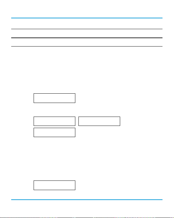
Rev. A | 2019.07 cGas Detector Digital Transmitter - Operation Manual
The factory default calibration gas concentrations are:
SENSO R GAS TY PE C ALIBRATION GAS LEVEL
Oxygen (O2) 20.9% VOL
Either use a cylinder of 20.9% Oxygen or if you are con dent of the air quality, the oxygen in the
breathing environment can be used as a fairly accurate source of span gas (be careful not to exhale
in the direction of the Oxygen sensor vent). It is not recommended to use this procedure for all span
adjustments of Oxygen sensors.
Attach the regulator to the span gas cylinder and ow the span gas over the sensor. You have 120
seconds to start owing the gas. If the gas isn’t detected, the display will return to Calibrate Span.
Waiting for Gas
53AD
35s
When the gas is detected the display will show stabilizing for a countdown from 120 seconds and
then spanning for a countdown from 60 seconds.
Stabilizing
1961AD
Span Success
1956 AD 19
82s
Spanning
1957AD
21s
When the process has nished and the Span calibration was accepted, remove the cylinder of span
gas. Refer to Section 9.3.5 Span Override if the Span calibration was not successful.
Attach the regulator to the cylinder of Nitrogen (N2), insert calibration adapter into the sensor
opening on the front of the enclosure door (refer to Section 9.3.1 Calibration Adapter Plug if the
adapter will not t). Flow the gas for a couple minutes and continue owing while you press the UP
button to nd Calibrate Zero.
Calibrate Zero
Press ENTER to start the Zero calibration. The display will show a countdown from 19 seconds.
© 2019 All rights reserved. Data subject to change without notice. 59
100 AD
Page 60
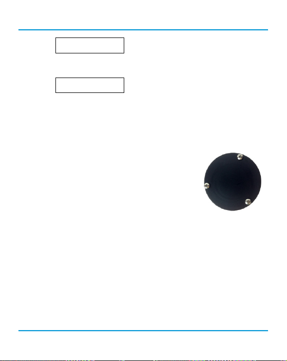
cGas Detector Digital Transmitter - Operation Manual Rev. A | 2019.07
Zeroing
47AD
18s
When the process has nished and the Zero calibration was accepted, press ENTER to Exit and
remove the cylinder of Nitrogen (N2) gas.
Zero Success
56AD
Refer to Section 9.3.4 Zero Override if the Zero calibration was not successful.
10 ACCESSORIES
10.1 Splash Guard (Option -S)
The splash guard attaches to the front of the enclosure to protect the
sensor during water spray or washdown applications. It is factory
installed and when attached the enclosure meets IP54 standards. To
calibrate a device with a splash guard, use the Cal Clip. This type of
splash guard can be used with any gas type except sticky gases. Refer
to Section 10.3 Splash Guard (Option -SN) for more information.
NOTE: The splash guard will slow down the response time of the sensor.
10.2 Calibration Adapter Clip “Cal Clip” (p/n: CET-SGC)
To calibrate a cGas Detector with a factory installed splash guard (Option -S), attach the Cal Clip
around the splash guard to allow the use of both hands during calibration. The small barb hose
tting accommodates standard or Te on tubing of 1/8” (3.175 mm) ID and 3/16” (4.762 mm) ID.
60 © 2019 All rights reserved. Data subject to change without notice.
Page 61
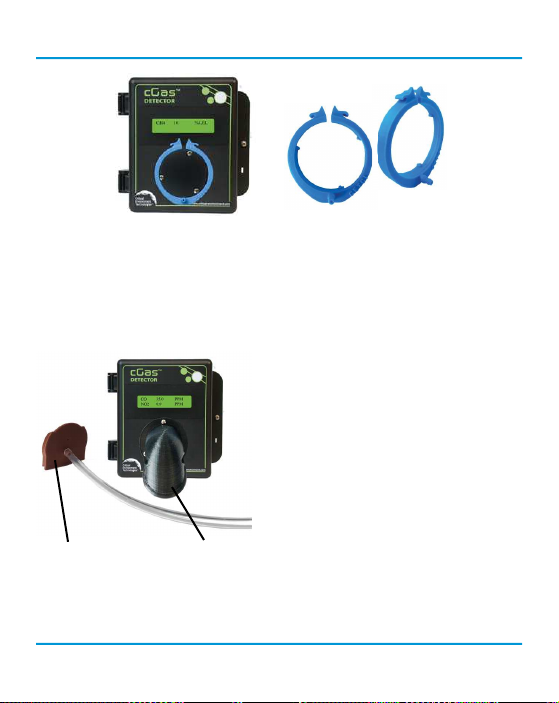
Rev. A | 2019.07 cGas Detector Digital Transmitter - Operation Manual
NOTE: The Cal Clip is designed to prevent entry or exit of air except via the hose barb tting,
therefore it must be removed during normal operation or else the gas readings will not be
accurate.
10.3 Splash Guard for Sticky Gases (Option -SN)
This specially designed Splash Guard for sticky gases is an optional factory installed accessory for
Calibration Adapter Clip Splash Guard
protection of a sticky gas sensor (such as Chlorine,
Chlorine Dioxide, Ozone or Hydrogen Chloride) in
wet and/or wash down environments.
NOTE: The Splash Guard for sticky gases comes
with a specialized Calibration Adapter Slide
Cap which MUST be removed during normal
operation or else the gas readings will not be
accurate.
© 2019 All rights reserved. Data subject to change without notice. 61
Page 62
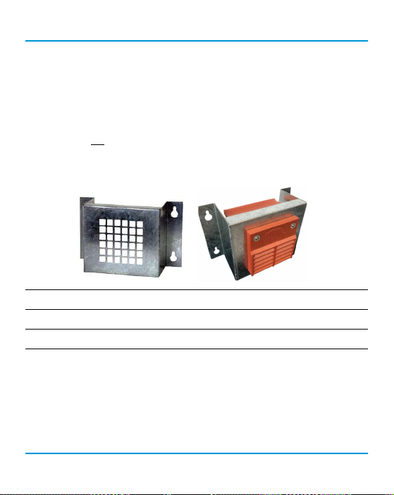
cGas Detector Digital Transmitter - Operation Manual Rev. A | 2019.07
10.4 Metal Protective Guard (p/n: SCS-8000-RSG)
The metal protective guard (p/n: SCS-8000-RSG) is made of heavy gauge, galvanized metal and
helps protect against abrasive damage, theft and vandalism to the transmitters. The 16-gauge
galvanized steel has 13 mm (½ in) square openings in the front to allow gas and air to ow through
to the sensor. With only four slotted mounting holes, installation and removal for gas detector
servicing is easy. In applications where sticky gases are being monitored, such as Ozone, Chlorine or
Hydrogen Chloride and frequent wash-downs are required, the metal guard can be ordered with a
splash cover (p/n: SCS-8000-WSG). The splash cover is made of a material called PC CPE that allows
the sticky gas to reach the sensor without adhering to the vent opening, plus protects the sensor
from water ingress.
Enclosure 16 gauge galvanized steel
Weight 800 g (28 oz)
Size 178 mm W x 160 mm H x 91 mm D (7.0” W x 6.3” H x 3.6” D)
10.5 Calibration Kit (p/n: CET-715A-CK1)
Calibration Kit contains the items necessary for common eld and shop calibrations. It comes in
a durable, hard plastic carrying case and includes a regulator, adapters, humidi cation chamber,
brass tting, hand tools and tubing. It does not include cylinders of gas. These must be ordered
separately.
62 © 2019 All rights reserved. Data subject to change without notice.
Page 63
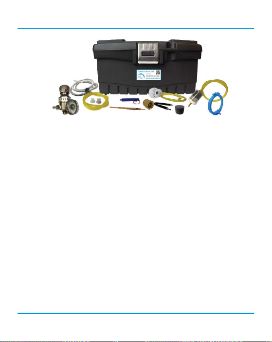
Rev. A | 2019.07 cGas Detector Digital Transmitter - Operation Manual
Calibration Kits and gases are available from the CETCI fac tory. Many gases, but not all are carried
The
in inventory. Check with any CETCI authorized distributor for availability of speci c gas types. Gas
cylinders cannot be shipped from Canada to other countries, including the USA.
11 MAINTENANCE
The cGas Detector transmitter requires virtually no maintenance other than regular calibration of
the sensor(s). There are no replaceable components except the sensors.
The transmitter should be monitored for possible damaging conditions.
• The sensor vents should be kept free of dirt or soot build up.
• If in a damp location, source of water should be shielded from contacting the top of the
transmitter.
• If located in a working area, the front of the transmitter should be kept clear.
• If painting is to be done in the same area as the transmitter, the transmitter needs to be
protected from over spray and the sensor vent should be covered so as to not receive paint
fumes. Paint fumes may damage and / or reduce the life of the sensor.
It is important to ensure that excess water and/or dust is not somehow entering the enclosure and
physically damaging the circuit board or internal components.
© 2019 All rights reserved. Data subject to change without notice. 63
Page 64

cGas Detector Digital Transmitter - Operation Manual Rev. A | 2019.07
12 TROUBLE SHOOTING
cGas Detector won’t power up. (blank display)
Is the power properly connected? Check the wiring connections. Refer to Section 6.7 Wiring
Connection in the cGas Detector Digital Installation Manual.
Display shows “ZERO FAULT” message.
The cGas Detector is unable to complete the zeroing (null) process. If using ambient air, make sure
there are no contaminants or residual target gas in the air. If using a cylinder of oxygen, use 20.99%
volume, scrubbed of hydrocarbons. In some cases nitrogen (N2) can be substituted for zero air when
null adjusting electrochemical sensors. Oxygen sensors require 99.9% N2 for a true zero. Catalytic
sensors require oxygen to work and thus the user MUST ow clean air or oxygen to obtain a true
zero and the span gas must have “air” balance, not N2 balance.
Display shows “SPAN FAULT” message.
Check all connections and possible interferences and try a complete calibration procedure from the
beginning again to see if this corrects the fault. If a second calibration does not resolve the fault
then the sensor needs to be replaced.
cGas Detector display shows “COMM” message.
Modbus® or BACnet output signal has not been connected properly. Check the wiring connections
and the network settings.
Device cannot be seen by the Controller and/or the BAS / DDC on the Modbus® network.
• Check the Baud rate. All devices in the network must have the same Baud rate.
• Check that local area network wiring is correct, especially the A and B lines to make sure
they are not swapped between devices on the network.
• Check the Modbus® ID. Each device must have a unique ID assigned to it.
64 © 2019 All rights reserved. Data subject to change without notice.
Page 65

Rev. A | 2019.07 cGas Detector Digital Transmitter - Operation Manual
Device cannot be seen by the Controller and/or the BAS / DDC on the BACnet® network.
• Check the Baud rate. All devices in the network must have the same Baud rate.
• Check to make sure the device has a unique ID assigned to it, which is made up of the MAC
ID and the Base ID.
• Check that local area network wiring is correct, especially the A and B lines to make sure
they are not swapped between devices on the network.
Frequent, unexpected alarm reading reported to BAS/DDC. Check to see if EMI and
RF interference is causing the equipment to react this way. Refer to Section 6.5.2 EMI and RF
Interference Considerations in the cGas Detector Digital Installation Manual for more information.
When calibrating a CO2 sensor, Calibrate Zero keeps failing or the Calibrate Span passes
but the gas level reading keeps climbing.
Start the calibration process over. Flow the nitrogen gas for 4 minutes before entering the Calibrate
Zero menu. Then ow the span gas for 4 minutes before entering the Calibrate Span menu.
List of Possible cGas Error Codes:
(appears on the display in place of the units for a channel)
Code Description
Check to make sure the smart sensor board is present
and installed properly in the socket. If installed, the cGas
F01 Negative Fault Reading
detects the sensor signal is too far below its zeroAD. May
be caused by a sensor that is temperature or humidity
sensitive. Zeroing the sensor will normally resolve this.
© 2019 All rights reserved. Data subject to change without notice. 65
Page 66

cGas Detector Digital Transmitter - Operation Manual Rev. A | 2019.07
cGas cannot communicate with the smart board. Ensure
F02 Smart Board Fault
the smart board is installed and installed on the correct
side (left) if a single channel unit. Otherwise power cycle or
replace the sensor smart board.
F03
CO2 Communication
Fault
cGas cannot communicate with the CO2 sensor even though
it can communicate with the smart board. Power cycle or
replace the sensor smart board.
The internal smart sensor board gainPOT chip has failed.
F04 POT chip has failed
If a power cycle does not resolve this, replace the sensor
smart board.
Error in reading Smart
F05
Board
FO6 SB ID Mismatch
cGas detected an error in the smart board ID. Use “Write to
Sensor” for the indicated channel (passcode 3022).
Firmware expected a di erent smart board than what is in
the sensor socket.
66 © 2019 All rights reserved. Data subject to change without notice.
Page 67

Rev. A | 2019.07 cGas Detector Digital Transmitter - Operation Manual
NOTES
© 2019 All rights reserved. Data subject to change without notice. 67
Page 68

Critical Environment Technologies Canada Inc.
Unit 145, 7391 Vantage Way, Delta, BC, V4G 1M3, Canada
Toll Free: +1.877.940.8741
Tel: +1.604.940.8741
Fax: +1.604.940.8745
www.critical-environment.com
CGAS-D-20190715-Rev-A
© 2019 Critical Environment Technologies Canada Inc. All rights reserved. Data in this publication may change without notice.
 Loading...