

Page 1
Critical Environment Technologies
Canada Inc.
www.critical-environment.com
Installation Manual for
AST
AST--
IS5
IS5
Analog transmitters with Infrared CO2
& Temperature sensors with LCD display & relay
#145, 7391 VANTAGE WAY
DELTA, BC CANADA V4G 1M3
PH: 604-940-8741 TOLL FREE: 877-940-8741
MANUAL REVISION-C, AUGUST 18, 2010
Page 2

2
Page 3

3
AST-IS5
ANALOG TRANSMITTER
with
INFRARED CO2 SENSOR & TEMPERATURE SENSOR
and
LCD DIGITAL DISPLAY
This AST-IS series are reliable, long lif e analog transmitters. Life expectan cy of the
infrared sensor is 15-years. The AST-IS5 is an advanced transmitter that has been
designed for use in the “climate zone”.
It provides an output for CO2 gas and an output for temperature. The local LCD
display provides real time values for the user. Standard measurement range is
0-2000 ppm.
SELF-DIAGNOSTICS
The system contains complete self diagnostic procedures. A full system test is
executed automatically every time the power is turned on. In addition, constantly
during operation, the sensors are checked against failure by checking the valid
dynamic measurement ranges. All EEPROM updates, initiated by the sensor itself
are checked by subsequent memory read back and data comparisons. These
different system checks return error bytes to the system RAM.
NOTE: The sensor accuracy is defined as continuous oper ation (at least 3-weeks
after installation).
Page 4
4
FUNCTIONAL DESCRIPTION
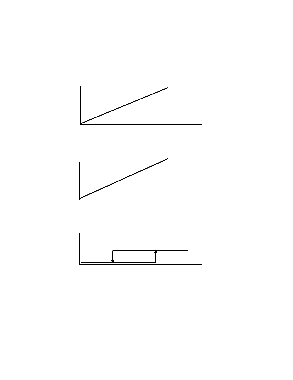
OUT-1 = Measuring signal of CO2 concentration lowest value - highest value.
OUT-2 = Measuring signal of temperature lowest value - highest value.
OUT-3 = ON / OFF signal of demand of air quality
The opening of the relay is controlled by the hysteresis of th e relay.
CO2 concentration
OUT-2 100%
Measuring
Signal
0%
lowest value highest value
* The measuring signal of CO2
Measured temperature
OUT-2 100%
Measuring
Signal
0%
lowest value highest value
* The measuring signal of temperature
Relay (ON / OFF)
Relay
Closed
Open
* The relay output
Page 5

5
TERMINAL DEFAULT
OUTPUT
DEFAULT
OUTPUT
RANGE
OUTPUTS OF
THIS SENSOR
OUTPUT
RANGE OF
THIS SENSOR
OUT-1 4-20 mA 0-2000 ppm CO2
OUT-2 0-10 VDC 0-50 deg. C.
RELAY Closed
Open
>1000 ppm CO2
<900 ppm CO2
DEFAULT OUTPUT CONFIGURATION FOR AST-IS5
Configuration Output Range Formula for Calculation
0-10 VDC 0-2000 ppm CO2
0-50 deg. C.
CO2 value = Volt / 10 * 2000
Temperature value in C = Volt / 10 * 50
2-10 VDC 0-2000 ppm CO2
0-50 deg. C.
CO2 value = (Volt-2) / 8 * 2000
Temperature value in C = (Volt-2) / 8 * 50
4-20 mA 0-2000 ppm CO2
0-50 deg. C.
CO2 value = (nA-4) * 2000 / 16
Temperature value in C = (mA-4) * 50 / 16
a-b c-d Value = (reading-a) / (b-a) * (d-c) + c
a = lowest value of the configuration
b = highest value of the configuration
c = lowest value of the range
d = highest value of the range
FORMULAS FOR CALCULATING OUTPUT VALUES
NOTE: RED LED is lit when the relay output is closed.
OUTPUT CONFIGURATIONS
JUMPER POSITION FUNCTION
Start point
selection jumper
0%
20%
Jumper top position provides 0VDC or 0mA start point
for OUT-1, OUT-2 (0-20 mA or 0-10 VDC)
Jumper bottom position provides 2VDC or 4mA start
point for OUT-1, OUT-2 (4-20 mA or 2-10 VDC)
OUT-1 Current
Voltage
Connection in position “Current” provides 0/4-20 mA
output range for OUT-1
Connection in position “Voltage” provides 0/2-10 VDC
output range for OUT-1
OUT-2 Current
Voltage
Connection in position “Current” provides 0/4-20 mA
output range for OUT-2
Connection in position “Voltage” provides 0/2-10 VDC
output range for OUT-2
Page 6
6
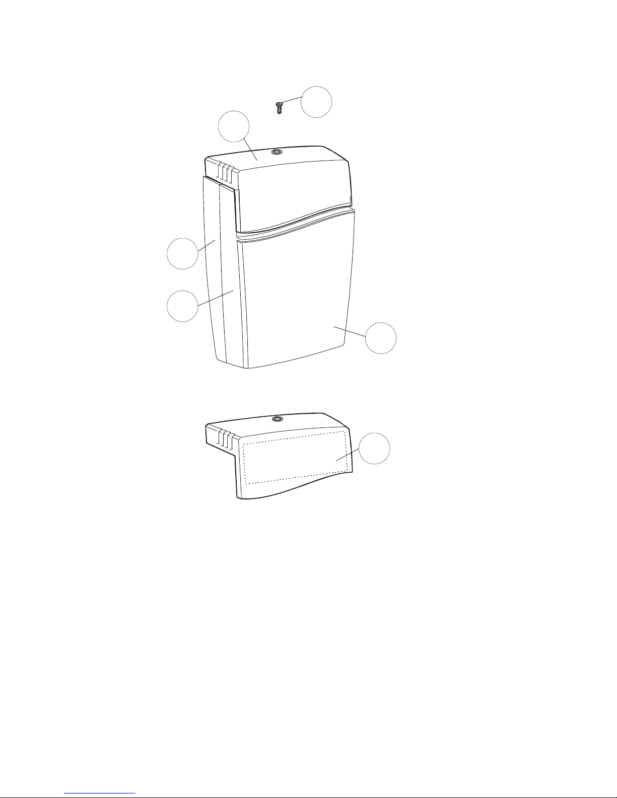
ITEM LOCATORS
1 top portion
2 lid
3 front portion
4 wall plate
5 screw
6 label with settings inside the top portion
4
3
2
6
1
5
DRAWING #1
INSTALLING THE TRANSMITTER
Page 7
7
INSTALLING THE TRANSMITTER, CONT’D…..
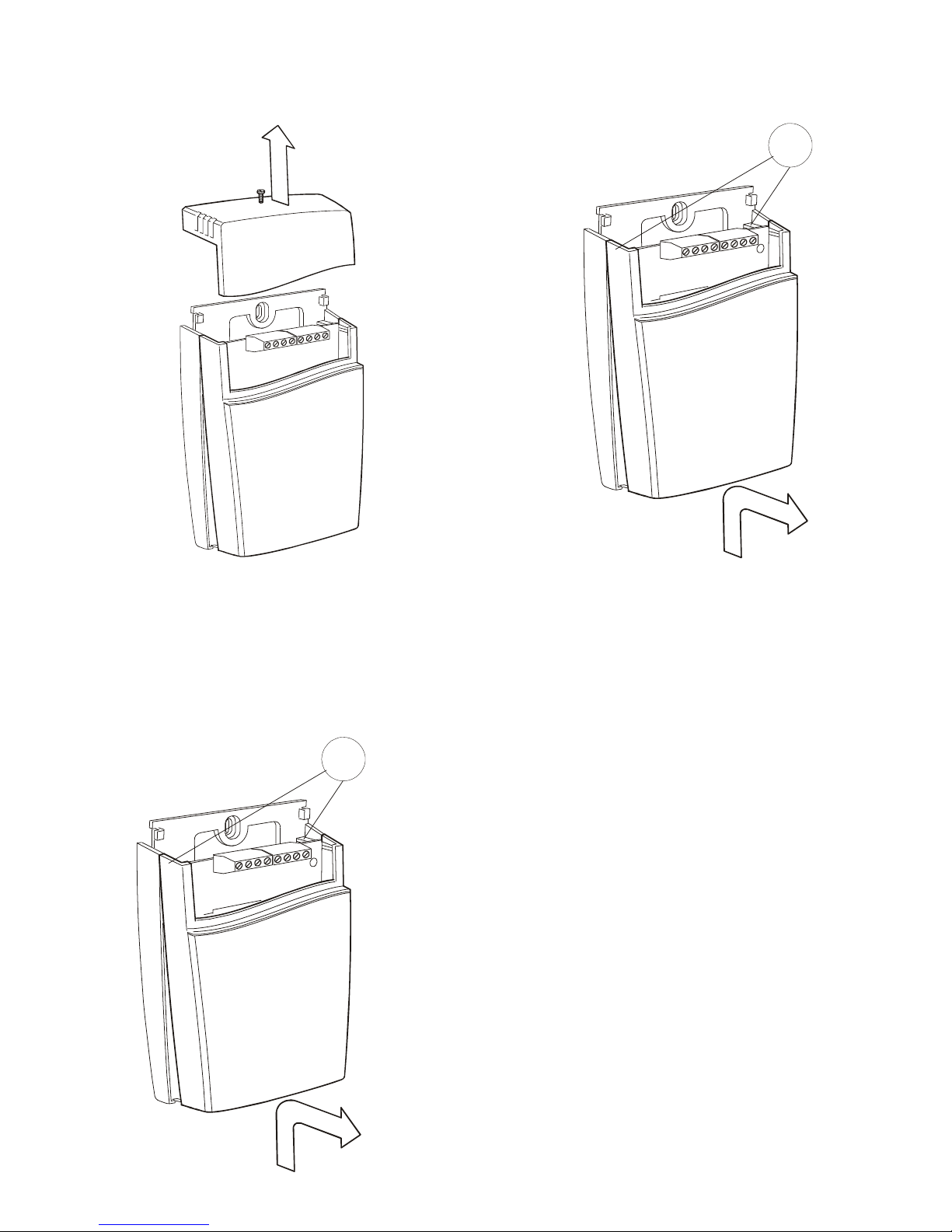
1
REMOVE THE SECURING SCREW
FROM THE TOP PORTION, ITEM-5 IN
ITEM LOCATOR ON PREVIOUS PAGE
PULL THE TOP PORTION
UPWARD TO REMOVE IT
1
FOLD THE FRONT PORTION (ITEM-3,
DRAWING-1) WITH THE LID (ITEM-2,
DRTAWING-1), FORWARD AND
LOOSEN IT FROM THE HOOKS (ITEM-1,
DRAWING-4)
DRAWING #2
DRAWING #3
DRAWING #4
Page 8
8
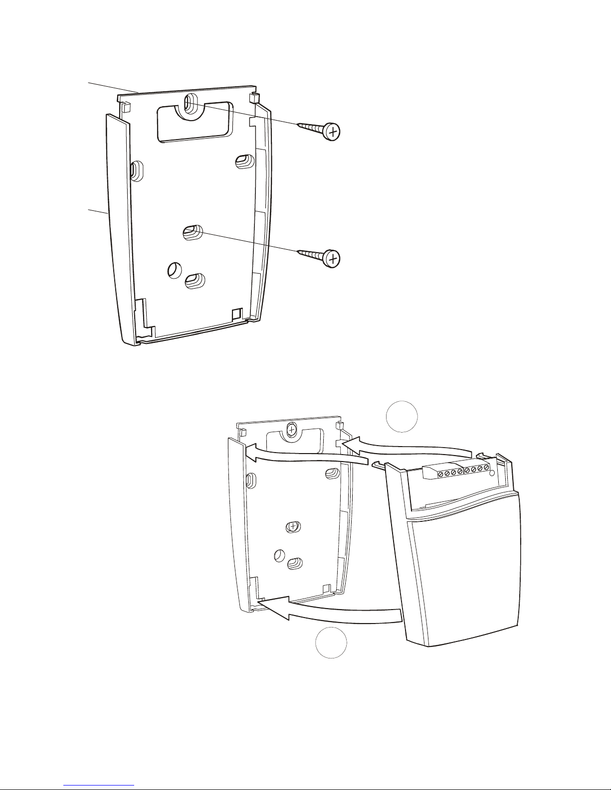
INSTALLING THE TRANSMITTER, CONT’D…..
A
B
SECURE THE WALL PLATE WITH
SCREWS. MAXIMUM SCREW HEAD DIAMTER SHOULD BE 7.5 mm. MAXIMUM
SCREW HEAD HEIGHT SHOULD BE 2.5
mm.
A - PUT THE TOP TABS OF THE FRONT PORTION INTO
THE TOP HOLES OF THE WALL PLATE.
B - PRESS THE LOWER EDGE OF THE CASE ONTO THE
WALL PLATE TO LATCH IN PLACE.
DRAWING #5
DRAWING #6
Page 9
9
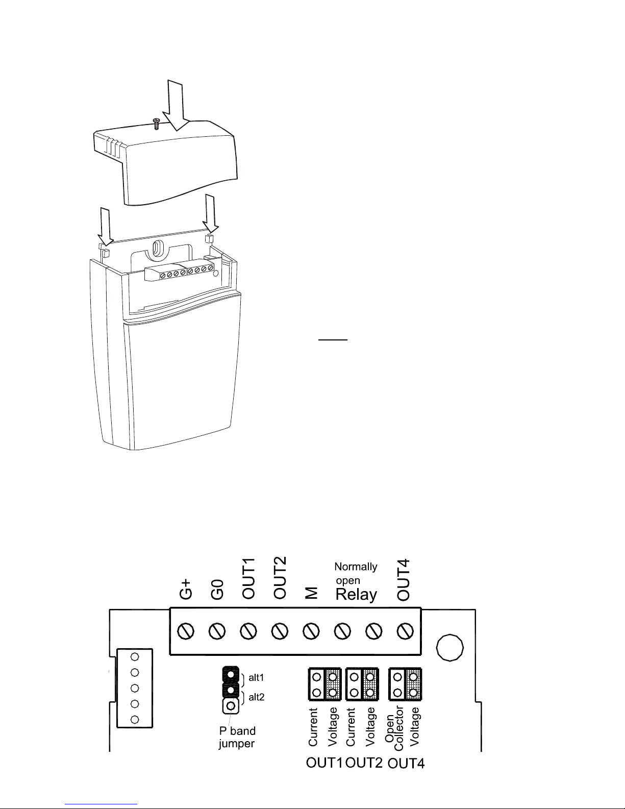
INSTALLING THE TRANSMITTER, CONT’D…..
THE TOP PORTION IS PUSHED UNDER
THE LOCKING HOOKS OF THE WALL
PLATE AND IS SECURED WITH A SCREW
DI1
TERMINALS & JUMPERS FOR AST-IS5:
THE TERMINALS & JUMPERS ARE LOCATED UNDER THE TOP PORTION.
THE DARKER AREAS ARE INDICATING THIS TRANSMITTER HAS BEEN SET FOR
VOLTAGE OUTPUT.
NOTE
: IF FOR SOME REASON THE PCB
MUST BE REMOVED, HANDLE IT VERY
CAREFULLY ONLY BY THE EDGES TO
PROTECT IT FROM STATIC DISCHARGE
DAMAGE. NORMALLY REMOVING THE
PCB IS NOT REQUIRED.
DRAWING #7
DRAWING #8
Page 10
10
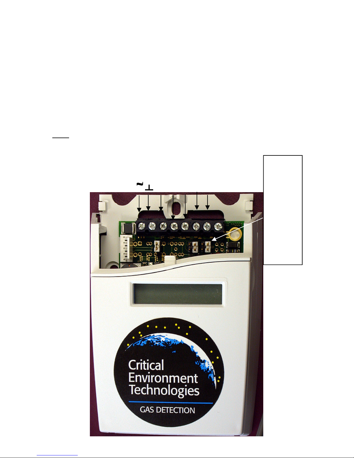
WIRING TERMINALS & SIGNAL OUTPUT JUMPER SETTINGS
OUT-2
OUT-1
+
POWER 24VAC / DC+
POWER GROUND (-)
ANALOG OUT 0-10VDC(+)
ANALOG OUT 4-20 mA(+)
CURRENT OUTPUT JUMPER SET
VOLTAGE OUTPUT JUMPER SET
REFERENCE DRAWING #8 ON
PAGE-7 FOR MORE DETAILS.
M - SIGNAL GROUND (-)
PHOTO #1
OUTPUT - 3 RELAY - CLOSED - >1000 PPM
OUTPUT - 3 RELAY - OPEN - <900 PPM
NOTE: STANDARD
RANGE IS 0-2000 PPM
Page 11
11
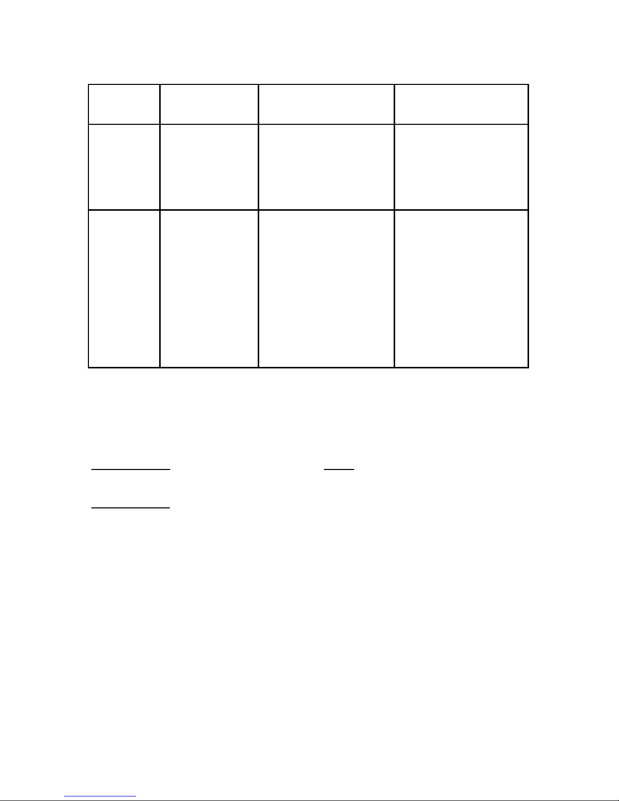
Connection
Terminal
Function
Electrical Data
Remarks
G+
G0
Power (+)
Power ground (-)
24 VAC/DC+ (+-20%), 3W
24 VAC/DC-
2W without output load
See note 1!
OUT 1
OUT 2
M
Analogue Output 1
(+)
Analogue Output 2
(+)
Signal Ground (-)
0-10 VDC or 0-20 mA,
2-10 VDC or 4-20 mA,
Same as Output 1
Connected to G0 via PTC
fuse
According to positions of
OUT1 and start point
jumpers.
See note 2!
According to positions of
OUT2 and start point
jumpers.
See note 2!
See note 1!
WIRING TERMINALS & SIGNAL OUTPUT JUMPER SETTINGS, CONT’D….
The power supply has to be connected to G+ and G0. G0 is considered as system
ground. If the analogue output is connected to a controller the same ground reference
has to be used for the AST-IS5 unit and for the control system! Unless different
transformers are used, special precautions need to be taken.
PLEASE NOTE
! The AST-IS5 signal ground is not galvanically separated from the
AST-IS6 power supply!
PLEASE NOTE
!
The same ground reference has to be used for the AST-IS5 unit and for the control
system!
Note 1: The ground terminal is used as negative power supply DC input or AC phase
ground G0 (halfwave rectifier). The signal ground M, is protected by a PTC resistor, is
the same as power ground G0 (permitting a ”3-wire” configuration). A single transformer
may be used for the entire system.
Note 2: AST-IS5 can deliver a voltage or a current loop for OUT1/OUT2. To change
between voltage and current output mode the hardware jumpers are used. There is one
jumper for OUT1 and one for OUT2, so that one output can be a voltage output and the
other a current output. Both, voltage output and current output, can have start points 0
% (0-10 VDC or 0-20mA) or 20% (2-10 VDC or 4-20mA). The same start point is used
for both outputs. See the function manual.
 Loading...