

Page 1
Operation Manual
www.critical-environment.com
ART Infrared Refrigerant Transmitter
Rev. 1 | 2014.02
Page 2

2 © 2014 All rights reserved. Data subject to change without notice.
ART - Operation Manual Rev. 1 | 2014.02
TABLE OF CONTENTS
1 POLICIES ............................................................................................... 5
1.1 Important Note .................................................................................................... 5
1.2 Warranty Policy .................................................................................................... 6
1.3 Service Policy .......................................................................................................6
1.4 Copyrights ............................................................................................................ 7
1.5 Disclaimer ............................................................................................................ 7
1.6 Revisions .............................................................................................................. 8
2 INTRODUCTION .................................................................................. 9
2.1 General Description .............................................................................................. 9
2.2 Key Features ......................................................................................................... 9
3 DETECTION OPTIONS ...................................................................... 10
3.1 Broadband Gas Detection................................................................................... 10
3.2 Gas Specic Detection ........................................................................................ 11
3.3 Changing Gas Types and Accuracy ...................................................................... 13
3.4 Remote Controller Options ................................................................................ 14
4 INSTRUMENT SPECIFICATIONS ...................................................... 14
4.1 Technical Specications ...................................................................................... 14
4.2 Enclosure Dimensions ........................................................................................ 17
5 FEATURES ........................................................................................... 18
5.1 Front Exterior Enclosure ..................................................................................... 18
5.2 Interior System Layout ....................................................................................... 20
5.2.1 Front of Enclosure ................................................................................. 20
5.2.2 Back of Enclosure .................................................................................. 21
6 MOUNTING ........................................................................................ 22
6.1 Warnings and Prerequisites ................................................................................ 22
6.2 Mounting Locations ........................................................................................... 23
6.2.1 General Placement Guidelines .............................................................. 23
6.2.2 Machinery Rooms ................................................................................. 23
Page 3

© 2014 All rights reserved. Data subject to change without notice. 3
Rev. 1 | 2014.02 ART - Operation Manual
6.2.3 Refrigerated Spaces .............................................................................. 24
6.2.4 Chillers .................................................................................................. 24
6.3 Mounting Procedure .......................................................................................... 25
7 WIRING AND CONFIGURATION ...................................................... 28
7.1 Overview ............................................................................................................ 28
7.2 Wiring Supply Power (24 VAC or 24 VDC) ............................................................ 28
7.2.1 Maintaining Neutral Polarity ................................................................ 30
7.3 Wiring Alarm Output (Analog Signal) ................................................................. 30
7.4 Wiring Digital Alarm Output Relay ..................................................................... 31
7.5 Modbus Network Conguration ......................................................................... 32
7.6 Conclusion ......................................................................................................... 35
8 OPERATION AND STABILIZATION ..................................................36
8.1 Power Up and Warm-up ..................................................................................... 36
8.2 Stabilization ....................................................................................................... 36
8.3 Perform a Manual Zero ....................................................................................... 36
8.4 Behavior During Alarm Conditions ..................................................................... 37
8.5 Gas Detector Faults ............................................................................................ 37
8.5.1 Overview .............................................................................................. 37
8.5.2 Non-Critical Faults ................................................................................ 37
8.5.3 Critical Faults ........................................................................................ 38
9 SETTING AND CONFIGURING THE PARAMETERS ........................ 39
9.1 User Interface Overview ..................................................................................... 39
9.2 Setting Parameters ............................................................................................ 40
9.2.1 Overview .............................................................................................. 40
9.2.2 Conguring Parameters ........................................................................ 40
9.3 Completing Setup .............................................................................................. 48
10 FUNCTIONAL TESTS AND GAS ADJUSTMENTS ......................... 49
10.1 Warnings and Cautions .................................................................................... 49
10.2 Bump Test vs Adjusting Detector Response ...................................................... 50
10.3 Bump Testing ................................................................................................... 51
Page 4

4 © 2014 All rights reserved. Data subject to change without notice.
ART - Operation Manual Rev. 1 | 2014.02
10.4 Adjustment Using Calibration Gas .................................................................... 52
11 MODBUS COMMUNICATIONS ...................................................... 54
11.1 Introduction ..................................................................................................... 54
11.2 Communication Settings .................................................................................. 55
11.3 Analog Input Registers ..................................................................................... 55
11.4 Analog Output Registers .................................................................................. 56
11.5 Input Status Flags ............................................................................................ 57
11.6 Output Status Flags .......................................................................................... 58
12 REPLACEMENT PARTS AND ACCESSORIES ................................ 59
12.1 Splash Guard .................................................................................................... 59
12.1.1 Splash Guard Mounting Template ....................................................... 60
12.2 Metal Protective Guard .................................................................................... 61
12.3 Calibration Kit .................................................................................................. 62
13 TROUBLE SHOOTING ..................................................................... 62
13.1 Fault Codes ....................................................................................................... 62
13.2 Diagnostic Attributes (P.-18) ............................................................................ 65
13.3 Resetting to Default Values .............................................................................. 66
Page 5

© 2014 All rights reserved. Data subject to change without notice. 5
Rev. 1 | 2014.02 ART - Operation Manual
1 POLICIES
1.1 Important Note
Read and understand this manual prior to using this instrument. Carefully read the
warranty policy, service policy, notices, disclaimers and revisions on the following pages.
This product must be installed by a qualied electrician or factory trained technician and
according to instructions indicated in this manual. This instrument should be inspected and
calibrated regularly by a qualied and trained technician. For more information, refer to
Section 10 Functional Tests and Gas Adjustments of this manual.
This instrument has not been designed to be intrinsically safe. For your safety, do not use it
in classied hazardous areas (explosion-rated environments).
INSTRUMENT SERIAL NUMBER:
________________________________________________
PURCHASE DATE:
________________________________________________
PURCHASED FROM:
________________________________________________
Page 6

6 © 2014 All rights reserved. Data subject to change without notice.
ART - Operation Manual Rev. 1 | 2014.02
1.2 Warranty Policy
Critical Environment Technologies Canada Inc. (CETCI), also referred to as the manufacturer,
warrants this instrument, excluding sensors, to be free from defects in materials and
workmanship for a period of two (2) years from the date of purchase by the original
owner.
Most sensors have a warranty period of one (1) year from the date of purchase. If the
product should become defective within this warranty period, we will repair or replace it at
our discretion. Please check with the manufacturer for specic sensor warranty.
The warranty status may be aected if the instrument has not been used and maintained as
per the instructions in this manual or has been abused, damaged, or modied in any way.
This instrument is only to be used for purposes stated herein. The manufacturer is not liable
for auxiliary interfaced equipment or consequential damage.
Due to ongoing research, development, and product testing, the manufacturer reserves the
right to change specications without notice. The information contained herein is based
on data considered accurate. However, no warranty is expressed or implied regarding the
accuracy of this data.
All goods must be shipped to the manufacturer by prepaid freight. All returned goods must
be pre-authorized by obtaining a return merchandise authorization (RMA) number. Contact
the manufacturer for a number and procedures required for product transport.
1.3 Service Policy
CETCI maintains an instrument service facility at the factory. Some CETCI distributors
/ agents may also have repair facilities; however, CETCI assumes no liability for service
performed by anyone other than CETCI personnel.
Repairs are warranted for 90 days after date of shipment (sensors have individual
warranties).
Should your instrument require non-warranty repair, you may contact the distributor from
Page 7

© 2014 All rights reserved. Data subject to change without notice. 7
Rev. 1 | 2014.02 ART - Operation Manual
whom it was purchased or you may contact CETCI directly.
Prior to shipping equipment to CETCI, contact our oce for an RMA #. All returned goods
must be accompanied with an RMA number.
If CETCI is to do the repair work, you may send the instrument, prepaid, to:
Attention: Service Department
Critical Environment Technologies Canada Inc.
Unit 145, 7391 Vantage Way
Delta, BC, V4G 1M3
Always include your Returned Merchandise Authorization (RMA) number, address,
telephone number, contact name, shipping / billing information, and a description of the
defect as you perceive it. You will be contacted with a cost estimate for expected repairs,
prior to the performance of any service work.
For liability reasons, CETCI has a policy of performing all needed repairs to restore the
instrument to full operating condition.
Pack the equipment well (in its original packing if possible), as we cannot be held
responsible for any damage incurred during shipping to our facility.
1.4 Copyrights
This manual is subject to copyright protection; all rights are reserved. Under international
and domestic copyright laws, this manual may not be copied or translated, in whole or in
part, in any manner or format, without the written permission of CETCI.
1.5 Disclaimer
Under no circumstances will CETCI be liable for any claims, losses or damages resulting
from or arising out of the repair or modication of this equipment by a party other than
CETCI service technicians, or by operation or use of the equipment other than in accordance
Page 8

8 © 2014 All rights reserved. Data subject to change without notice.
ART - Operation Manual Rev. 1 | 2014.02
with the printed instructions contained within this manual or if the equipment has been
improperly maintained or subjected to neglect or accident. Any of the forgoing will void the
warranty.
Under most local electrical codes, low voltage wires cannot be run within the same conduit
as line voltage wires. It is CETCI policy that all wiring of our products meet this requirement.
It is CETCI policy that all wiring be within properly grounded (earth or safety) conduit.
1.6 Revisions
This manual was written and published by CETCI. The manufacturer makes no warranty or
representation, expressed or implied including any warranty of merchantability or tness
for purpose, with respect to this manual.
All information contained in this manual is believed to be true and accurate at the time
of printing. However, as part of its continuing eorts to improve its products and their
documentation, the manufacturer reserves the right to make changes at any time without
notice. Revised copies of this manual can be obtained by contacting CETCI or visiting
www.critical-environment.com.
Should you detect any error or omission in this manual, please contact CETCI at the
following address:
Critical Environment Technologies Canada Inc.
Unit 145, 7391 Vantage Way, Delta, BC, V4G 1M3, Canada
Toll Free: +1.877.940.8741
Telephone: +1.604.940.8741
Fax: +1.604.940.8745
Email: [email protected]
Website: www.critical-environment.com
Page 9

© 2014 All rights reserved. Data subject to change without notice. 9
Rev. 1 | 2014.02 ART - Operation Manual
In no event will CETCI, its ocers or employees be liable for any direct, special, incidental
or consequential damages resulting from any defect in any manual, even if advised of the
possibility of such damages.
2 INTRODUCTION
2.1 General Description
Thank you for purchasing our ART Infrared Refrigerant Transmitter. The ART is a nondispersive infrared, state-of-the-art xed gas detector which can detect a wide range
of refrigerant gases. It can be used on a stand-alone basis, connected to a controller or
integrated into a Building Management System (BMS).
The ART can be used in locations that require continuous monitoring and to add gas
detection solutions to an existing system.
The ART is available in two models - Broadband and Gas Specic. The Broadband Gas
Detector is used as a general purpose, gross leak detector and is factory tested and certied.
If more accurate detection is needed, Gas Specic models are available, which are factory
certied and calibrated to the target refrigerant.
If after reading through the manual, you have any questions, please do not hesitate to
contact our service department for technical support.
2.2 Key Features
• Long-life, non-dispersive infrared sensor allows for accurate low-level leak detection
• Fast-responding, refrigerant-specic sensor with no cross interferences to non-
refrigerant gases
• Detects all refrigerants (CFC, HCFs, HCFC, HFOs) including HF01234yf, HFO1234ze,
R410a & R22)
• Modbus RTU interface to connect to BAS/BMS systems
Page 10

10 © 2014 All rights reserved. Data subject to change without notice.
ART - Operation Manual Rev. 1 | 2014.02
• On-board alarm relay
• User selectable analog output: 4 - 20 mA, 0 - 5V, 1 - 5V, 0 - 10V, 2 - 10V
• LED real-time display with on-board audible and visual alarms
3 DETECTION OPTIONS
The ART gas detector is available in two models:
• Broadband Gas Detector used for gross leak detection, or
• Gas Specic Detector that is more distinct, pre-calibrated and characterized for
response to specic refrigerants
3.1 Broadband Gas Detection
The ART Broadband Gas Detector (Part Code: ART-B) is used as a general purpose gross leak
detector and is factory tested and certied. The refrigerants are combined into three groups
and is shipped with the accuracy indicated in the chart on the next page. Measurement
performance is based on an average response prole for all of the gases within the group.
For more information on Value for Parameter 11, see Section 9 Setting and Conguring the
Parameters.
Page 11

© 2014 All rights reserved. Data subject to change without notice. 11
Rev. 1 | 2014.02 ART - Operation Manual
GROUP #
VALUE FOR
PARAMETER 11
REFRIGERANT AS SHIPPED ACCURACY
1 P. -11 = 1
R123 ±30 PPM ±35%
R134a ±30 PPM ±25%
R404a ±30 PPM ±35%
R407a ±30 PPM ±25%
R407c ±30 PPM ±20%
R407f ±30 PPM ±20%
R410a ±30 PPM ±20%
R427a ±30 PPM ±15%
R507 ±30 PPM ±35%
2 P.11 = 2
R422a ±30 PPM ±25%
R422d ±30 PPM ±20%
HFO1234yf ±30 PPM ±25%
HFO1234ze ±30 PPM ±25%
3 P.-11 = 3 R22 ±30 PPM ±25%
NOTE: Greater accuracy may be achieved through the use of calibration gas and the
adjustment procedure detailed in Section 10 Functional Tests and Gas Adjustments.
3.2 Gas Specic Detection
If more accurate detection is needed, the ART Gas Specic Detector is shipped factory
certied and calibrated to the target refrigerant. For more information on Parameter 11 and
refrigerant conguration instructions, see Section 9 Setting and Conguring the Parameters.
Page 12

12 © 2014 All rights reserved. Data subject to change without notice.
ART - Operation Manual Rev. 1 | 2014.02
PART NUMBER REFRIGERANT ACCURACY
ART-R22 R22
±30 ppm ±5%
ART-R123 R123
±30 ppm ±5%
ART-134A R134a
±30 ppm ±5%
ART-R404A R404a
±30 ppm ±5%
ART-R407A R407a
±30 ppm ±3%
ART-R407C R407c
±30 ppm ±3%
ART-R407F R407f
±30 ppm ±3%
ART-R410A R410a
±30 ppm ±3%
ART-R422A R422a
±30 ppm ±5%
ART-R422D R422d
±30 ppm ±5%
ART-R427A
R427a ±30 ppm ±3%
ART-R507
R507 ±30 ppm ±5%
ART-HFO1234YF
HFO1234yf ±30 ppm ±5%
ART-HFO1234ZE
HFO1234ze ±30 ppm ±5%
NOTE: Gas specic detectors can be re-calibrated in the eld to new target gases. Use
optional calibration instructions in Section 10 Functional Tests and Gas Adjustments for
increased accuracy when detecting a new target gas that is dierent from the “as shipped”
target gas. Refer to Section 3.3 Changing Gas Types and Accuracy below.
Page 13
© 2014 All rights reserved. Data subject to change without notice. 13
Rev. 1 | 2014.02 ART - Operation Manual
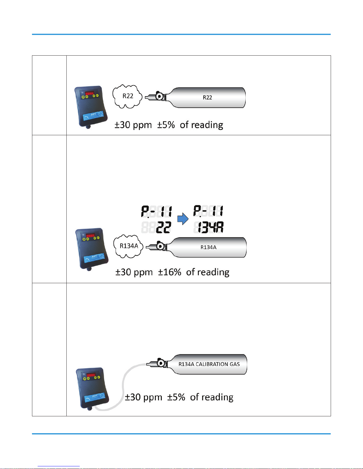
3.3 Changing Gas Types and Accuracy
As Shipped
The ART-R22 is factory calibrated to R22 and has an AS-SHIPPED R22 response
accuracy of ±30 ppm ±5% of reading.
Changed Gas Type
(Reduced Accuracy)
The gas detector may be changed to respond to any of the other listed
refrigerants (see Parameter P.-11 in Section 9.2 Setting Parameters). If
changed, the gas detector will have a lower accuracy for the target refrigerant
(without calibration). In this example, that accuracy is ±30 ppm ±16% of
reading.
Optional Calibration
(For Improved Accuracy)
By applying calibration gas containing the NEW target refrigerant, and via
the routine described in Section 10.4 Adjustment Using Calibration Gas, the
gas detector may then be adjusted to respond with the calibrated accuracy
of ±30 ppm ±5% of reading as shown in the chart in Section 3.2 Gas Specic
Detection.
Page 14

14 © 2014 All rights reserved. Data subject to change without notice.
ART - Operation Manual Rev. 1 | 2014.02
3.4 Remote Controller Options
The ART can connect to any controller through the standard analog output (voltage and
current: see 4.1 Technical Specications below), the standard alarm relay, or the digital
Modbus RTU communications interface.
4 INSTRUMENT SPECIFICATIONS
4.1 Technical Specications
GAS TYPE
Refrigerants
Group 1 R123, R134a, R404a, R407a, R407c, R407f. R410a, R427a, R507
Group 2 R422a, R422d, HFO1234yf, HFO1234ze
Group 3 R22
MECHANICAL
Enclosure ABS plastic with a UL ammability rating of 94V-0
Weight 180 g (0.40 lb) (6.3 oz)
Size 4.0” x 5.9” x 1.5” (102 mm x 150 mm x 40 mm)
ELECTRICAL
Power Requirement 24 VDC, 24 VAC, 50 - 60 Hz, 2.5 W max
Wiring
24VAC or 24VDC two-conductor shielded 14 to 22 AWG stranded
within conduit
Page 15

© 2014 All rights reserved. Data subject to change without notice. 15
Rev. 1 | 2014.02 ART - Operation Manual
Communication:
Modbus RTU over
RS-485
Baud rate:
Start bits:
Data bits:
Parity:
Stop bits:
Re-entry time:
End of msg:
9,600 or 19,200 (selectable)
1
8
none, odd, even (programmable)
1 or 2 (programmable)
500 ms (min time between retries)
silent 3.5 characters
INPUT / OUTPUT
Analog Outputs 4 20- mA, 0 - 5V, 0 - 10 V, 1 - 5V, 2 - 10V
Relays One relay rated 1 A @ 24 VAC/VDC (0.5A, 125V AC UL rating)
IP Rating
Not IP rated. An accessory splash guard is available for areas
requiring additional protection from wash down.
SENSOR
Type Infrared
Range 0 - 3,500 ppm
Squelch* Readings below 75 ppm are squelched by default
Response Time, T
90
< 5 minutes
USER INTERFACE
Display
Green LED Power ON indicator and bright, alpha-numeric LED
real-time display
Audible Alarm
Buzzer; enable/disable
Page 16

16 © 2014 All rights reserved. Data subject to change without notice.
ART - Operation Manual Rev. 1 | 2014.02
Visual Alarm Red 4-digit LED display
Alarm Delay Selectable; 0 to 15 minutes
Fault Monitoring Fault codes presented to user
ENVIRONMENTAL
Operating
Temperature
-30°C to 40°C (-22°F to 104°F)
Operating
Humidity
5 - 90% RH non-condensing
CERTIFICATIONS
CE / UL / CSA / IEC / EN 61010-1
NOTE: * When ltering is disabled (see Parameter P.-19 on page 48), the unit will respond
to concentrations sub -10 ppm.
Page 17
© 2014 All rights reserved. Data subject to change without notice. 17
Rev. 1 | 2014.02 ART - Operation Manual
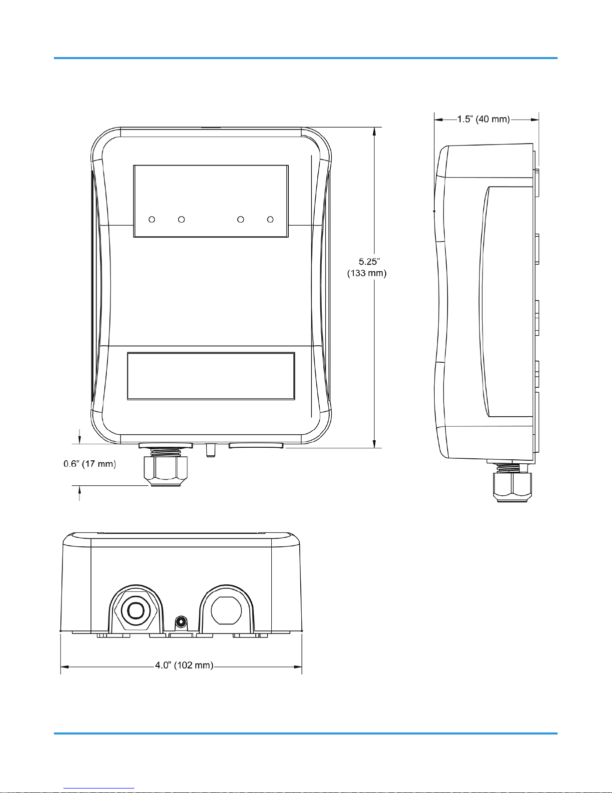
4.2 Enclosure Dimensions
Page 18
18 © 2014 All rights reserved. Data subject to change without notice.
ART - Operation Manual Rev. 1 | 2014.02
5 FEATURES
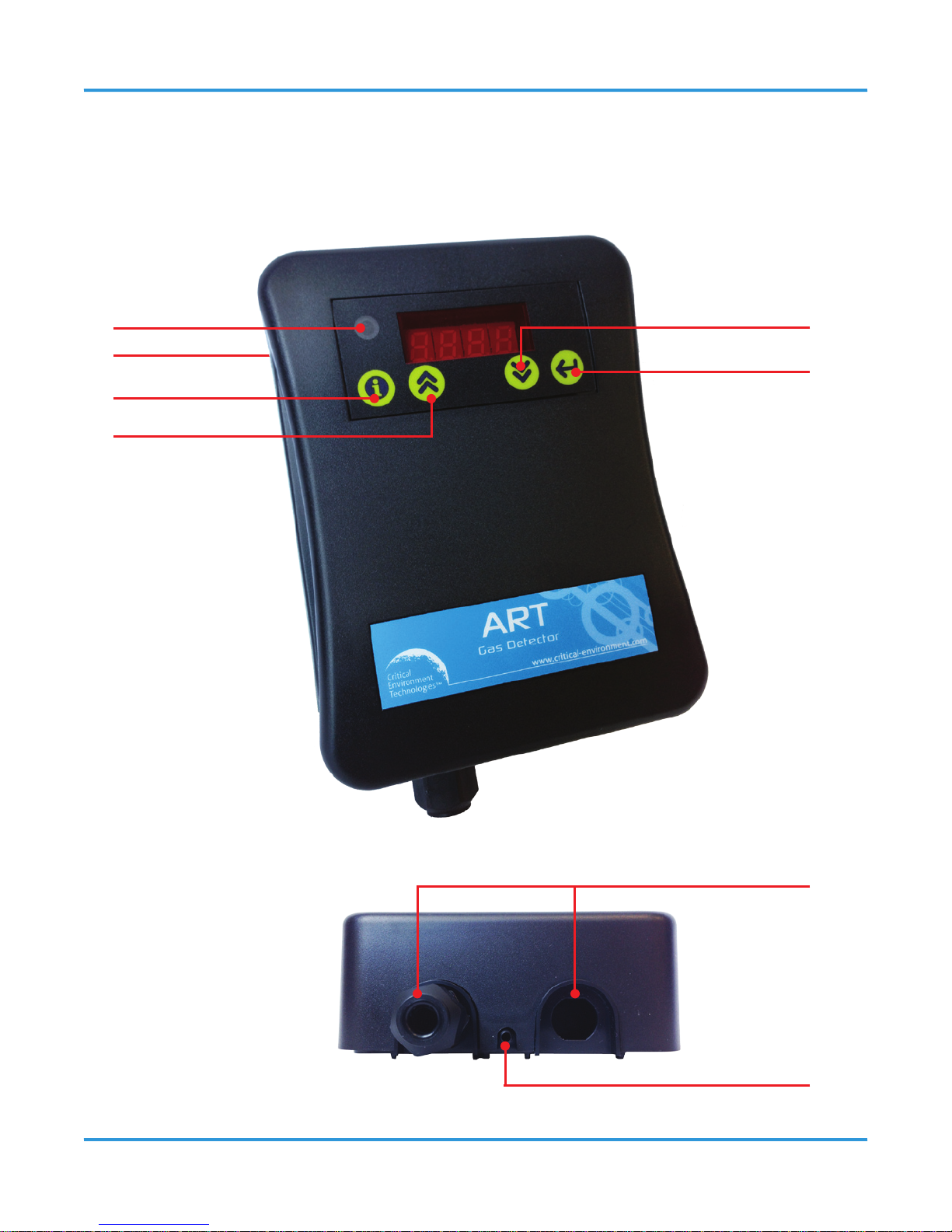
5.1 Front Exterior Enclosure
Page 19

© 2014 All rights reserved. Data subject to change without notice. 19
Rev. 1 | 2014.02 ART - Operation Manual
NUMBER FEATURE FUNCTION
Power LED Green LED, indicates unit power is ON.
4-digit LED Display
Alpha-numeric display (to show concentration in
real-time)
Information Button
Used to access the parameter list. Used to back up
one level without writing to memory when the
parameter list is active. Used to mute the audible
alarm for the time period congured in parameter
P.-12.
Up Button
Used to increment the value or parameter
displayed.
Down Button
Used to decrement the value or parameter
displayed. (When the Up Button and Down
Button are pressed and held together for 5
seconds, this key combination manually zeroes
the gas detector.)
Enter/Select Button
Saves the currently displayed parameter to
memory.
Cable Glands
(2 places)
Pre-installed cable gland is on the left. The
optional cable gland is on the right (if installed).
See Section 7 Wiring and Conguration.
Test Gas Port Used to connect the regulator during testing.
Page 20
20 © 2014 All rights reserved. Data subject to change without notice.
ART - Operation Manual Rev. 1 | 2014.02
5.2 Interior System Layout
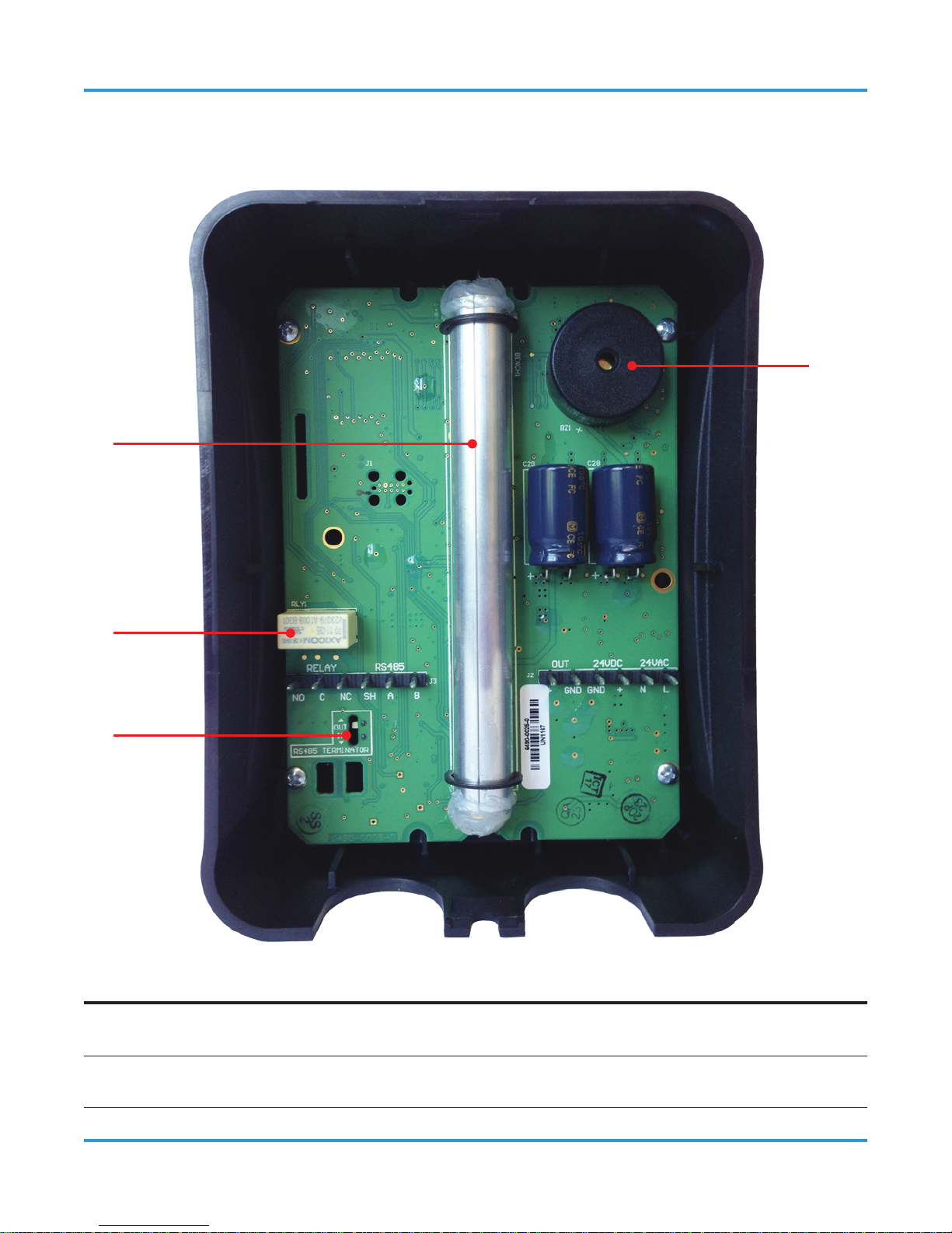
5.2.1 Front of the Enclosure
NUMBER FEATURE FUNCTION
IR Bench Location of the Infrared sensor.
Relay
Pluggable terminal for relay connection.
Page 21
© 2014 All rights reserved. Data subject to change without notice. 21
Rev. 1 | 2014.02 ART - Operation Manual
Modbus end of line
jumper
Critical for good communication.
Audible alarm
Default setting is enabled.
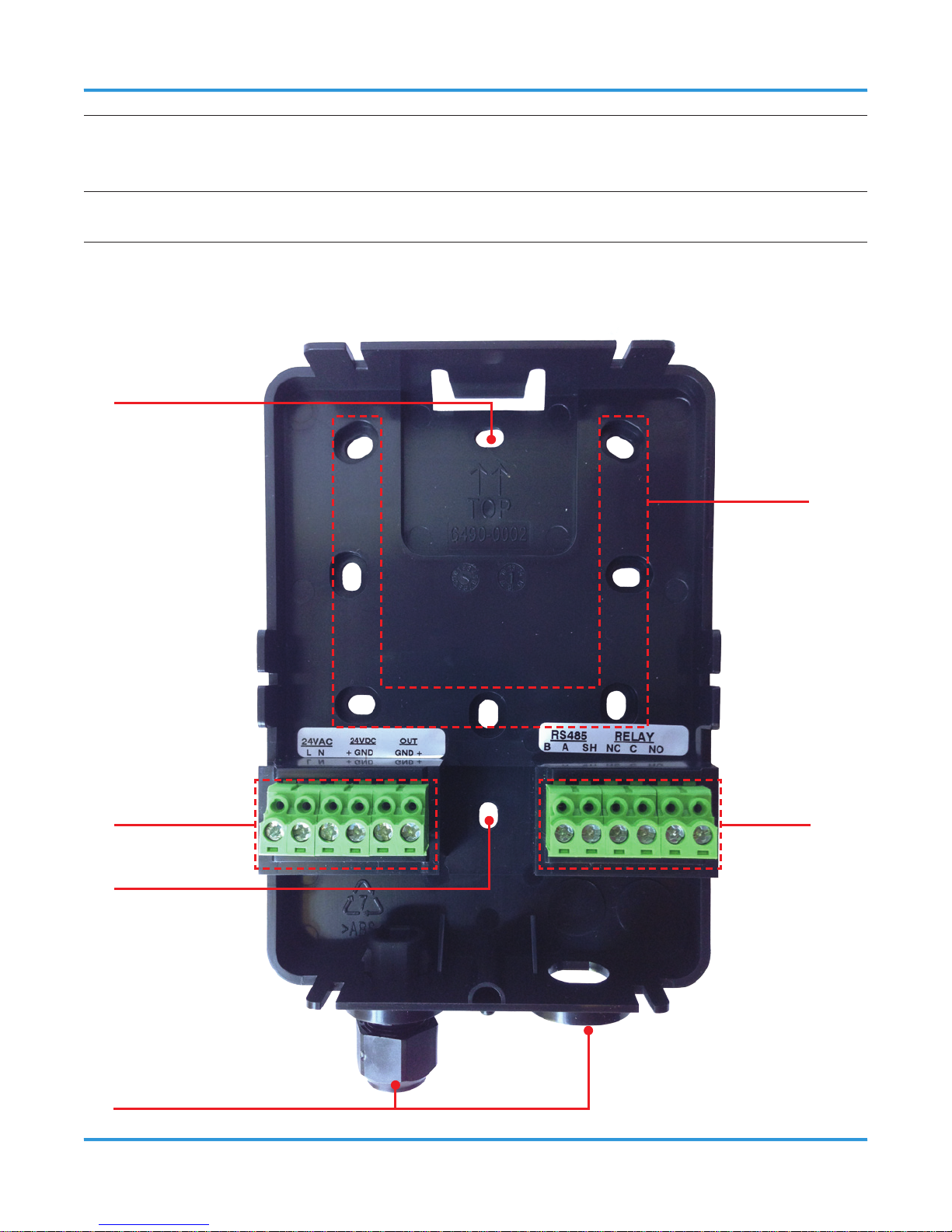
5.2.2 Back of the Enclosure
Page 22

22 © 2014 All rights reserved. Data subject to change without notice.
ART - Operation Manual Rev. 1 | 2014.02
NUMBER FEATURE FUNCTION
Junction box mounting
holes
Use hole pattern to mark the mounting
locations as needed and attach ART
base to junction box using mounting
hardware through these holes.
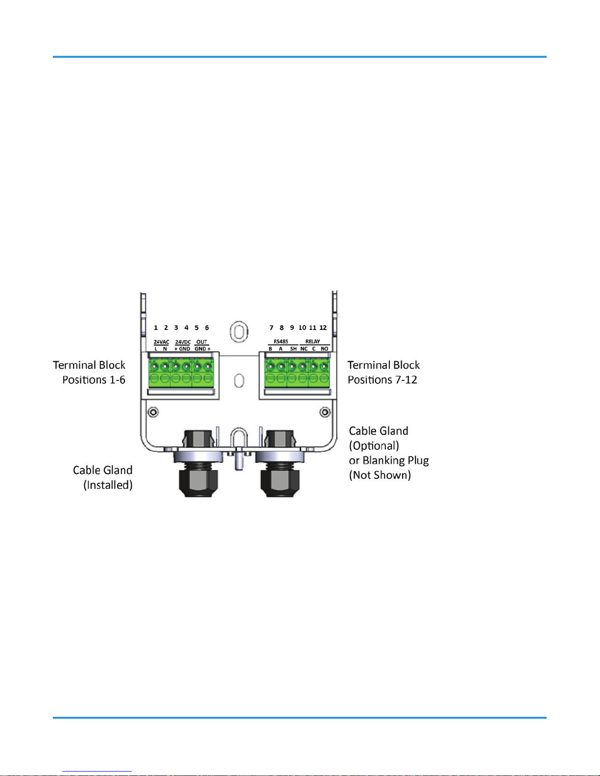
Terminal Block
Positions 1-6
AC, DC and Analog wiring
Cable Gland / Blanking
Plug
Pre-installed cable gland is on the left.
The optional cable gland is on the right,
if installed (each with a 1/4 inch cable
capacity). See Section 7 Wiring and
Conguration.
Flat surface mounting
holes
Use to attach ART base to wall mount
or other at surface using #6 screws
provided.
Terminal Block
Positions 7-12
Relay (alarm) output wiring and Modbus
network connection wiring
6 MOUNTING
6.1 Warnings and Prerequisites
WARNING: Explosion hazard. DO NOT mount the ART in an area that may contain
ammable liquids, vapors, or aerosols. Operation of any electrical equipment in such an
environment constitutes a safety hazard.
CAUTION:
• The ART contains sensitive electronic components that can easily be damaged. DO NOT
touch or disturb any of these components.
Page 23

© 2014 All rights reserved. Data subject to change without notice. 23
Rev. 1 | 2014.02 ART - Operation Manual
• DO NOT mount the ART directly to vibrating machinery as the vibrations may degrade
the gas detector’s performance.
NOTES:
• The mounting location of the monitor should allow it to be easily accessible for visual
monitoring and servicing.
• The monitor must be connected to a marked, suitably located and easily reached
switch or circuit-breaker as means of disconnection.
• Connect monitor power and signaling terminals using wiring that complies with local
electrical codes or regulations for the intended application.
6.2 Mounting Locations
6.2.1 General Placement Guidelines
The ART should be installed plumb and level and securely fastened to a rigid mounting
surface. Gas detectors must be located within the appropriate wire lengths from the central
control unit (if used).
NOTE: When installed in areas that may be subjected to water spray, the optional splash
guard should be used in conjunction with the ART.
6.2.2 Machinery Rooms
There is no absolute rule in determining the number of gas detectors and their locations.
However, a number of simple guidelines will help to make a decision. Gas detectors
monitor a point as opposed to an area. If the gas leak does not reach the detector then
no alarm will be triggered. Therefore, it is extremely important to carefully select the gas
detector location. Also consider ease of access for maintenance.
The size and nature of the site will help to decide which method is the most appropriate
to use. Locations requiring the most protection in a machinery or plant room would be
around compressors, pressurized storage vessels, refrigerant cylinders or storage rooms
or pipelines. The most common leak sources are valves, gauges, anges, joints (brazed or
Page 24

24 © 2014 All rights reserved. Data subject to change without notice.
ART - Operation Manual Rev. 1 | 2014.02
mechanical), lling or draining connections, etc.
In machinery rooms where there is little or no airow, placement options are:
• Point Detection, where gas detectors are located as near as possible to the most likely
sources of leakage, such as the compressor, expansion valves, mechanical joints or
cable duct trenches.
• Perimeter Detection, where gas detectors completely surround the area or equipment.
• Halocarbon and hydrocarbon refrigerants are heavier-than-air gases and as such the
gas detectors should be located near ground level (6 to 18 inches from the oor).
NOTE: Gas detectors should be positioned just far enough back from any high-pressure
parts to allow gas clouds to form and be detected. Otherwise, a gas leak might pass by in a
high-speed jet and not be detected by the gas detector.
• Make sure that pits, stairwells and trenches are monitored since they may ll with
stagnant pockets of gas.
• For racks or chillers pre-tted with refrigerant gas detectors, these should be mounted
so as to monitor the compressors.
• Do not mount the gas detector directly to pipes or structures that are subject to strong
vibration.
6.2.3 Refrigerated Spaces
In refrigerated spaces, gas detectors should be located away from doors, in the return
airow to the evaporators on a sidewall (below head-high is preferred), or on the ceiling,
not directly in front of an evaporator, nor in any direct airow. In large rooms with multiple
evaporators, gas detectors should be mounted on the central line between two adjacent
evaporators, as turbulence will result in airows mixing.
6.2.4 Chillers
In the case of small water- or air-cooled enclosed chiller units mount the gas detector so as
to monitor airow to the extract fans. With larger models also place a gas detector inside
Page 25
© 2014 All rights reserved. Data subject to change without notice. 25
Rev. 1 | 2014.02 ART - Operation Manual
the enclosure under or adjacent to the compressors.
For enclosed air-cooled chillers or the outdoor unit for variable refrigerant volume and
variable refrigerant ow (VRV/VRF) systems, mount the gas detector so as to monitor
airow to the extract fan. With large units also place a gas detector inside the enclosure
under or adjacent to the compressors.
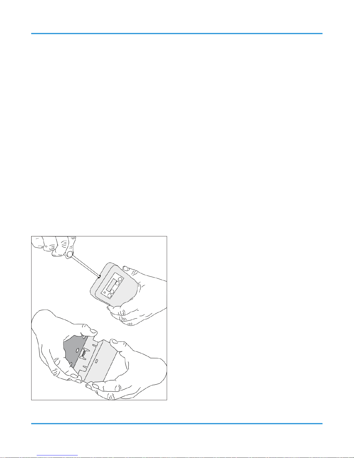
6.3 Mounting Procedure
To open the housing as received, use a at blade screwdriver and depress the top latch.
While pushing the latch grasp the back edge of the housing near the latch and pull the back
away.
When mounted, the housing is simply opened by pressing the top latch with a suitable
screwdriver or other at blade. With the top latch depressed pull the housing apart by
grasping the sides and pulling straight out. With the housing separated the mounting base
with terminal blocks will be visible.
Page 26

26 © 2014 All rights reserved. Data subject to change without notice.
ART - Operation Manual Rev. 1 | 2014.02
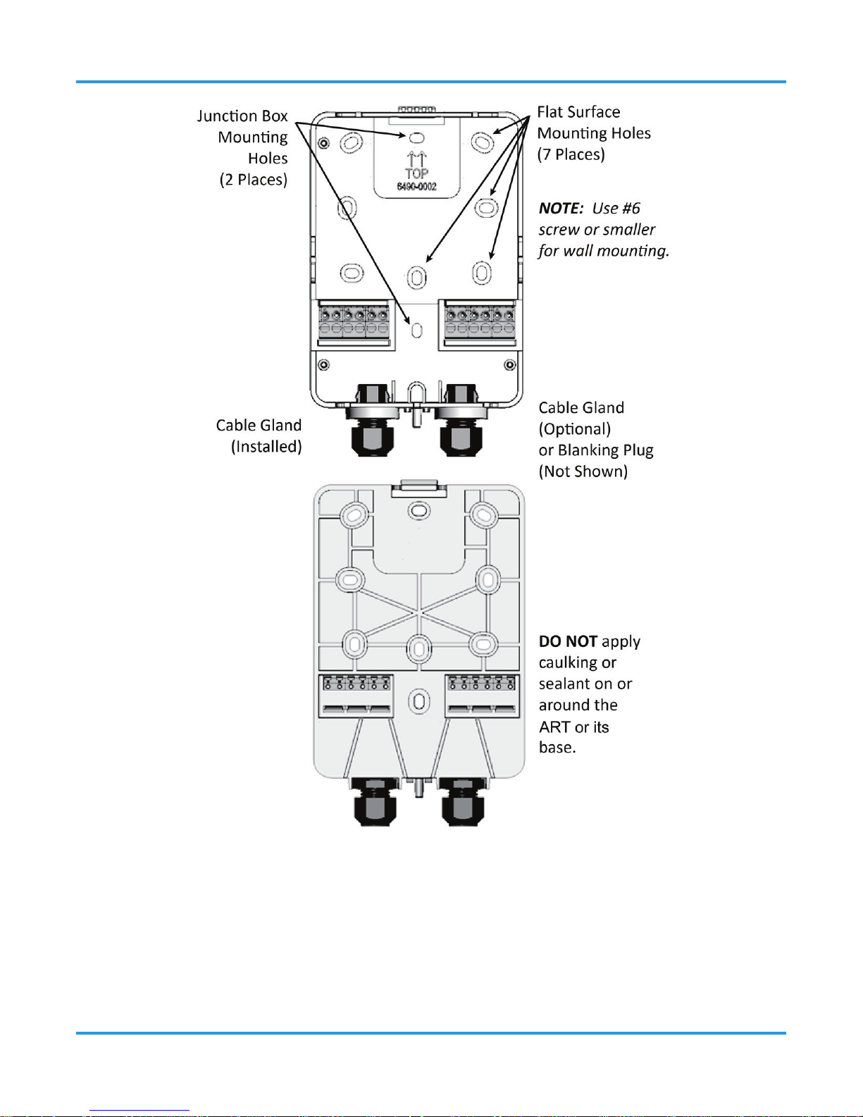
NOTE: Do not apply caulking or other material around the gas detector base. The gas
detector relies on air exchange through the spaces between the base and the gas detector
housing. Do not obstruct the small gap around the housing and the base with any material.
Step 1:
Open the housing.
Step 2:
Position the base to the pre-determined (acceptable) mounting location. Use the gas
detector base to mark the mounting location as needed. The hole pattern on the back plate
is sized to mount the gas detector onto various electrical junction boxes. The other holes
may be used as needed to mount the gas detector to other structures, or onto a wall.
Step 3: Wall Mount (if doing a junction box mount, go to Step 4)
Attach the ART base to the mounting surface using two #6 screws (provided) through two
of the 7 at surface mounting holes, being careful not to over-tighten the screws.
Step 4: Junction Box Mount (if doing a wall mount, see Step 3)
Attach the ART base to the junction box (using mounting hardware provided with your
junction box) through the two junction box holes. See diagram above.
Step 5:
Unless you are ready to wire the device (see Section 7 Wiring and Conguration) carefully
snap the cover onto the base unit.
Page 27
© 2014 All rights reserved. Data subject to change without notice. 27
Rev. 1 | 2014.02 ART - Operation Manual
Page 28
28 © 2014 All rights reserved. Data subject to change without notice.
ART - Operation Manual Rev. 1 | 2014.02
7 WIRING AND CONFIGURATION
7.1 Overview
Prior to wiring and conguring the ART, assure the following conditions have been met:
• ART back plate is mounted in an appropriate location
• The cover panel is removed.
If the cover panel was reattached after mounting, open the gas detector enclosure by
pressing the top latch with a suitable screwdriver or other at blade. With the top latch
depressed pull the housing apart by grasping the sides and pulling straight out. Align and
press together to close.
NOTES:
• The pre-installed cable gland (left) and optional cable gland (right) have a 1/4 inch
cable capacity (each).
• Install the optional cable gland on the right side of the base unit if needed. Otherwise,
install the blanking plug that is included in the mounting kit.
7.2 Wiring Supply Power (24 VAC or 24 VDC)
WARNING: Incorrect wiring may permanently damage the gas detector, and void the
Page 29
© 2014 All rights reserved. Data subject to change without notice. 29
Rev. 1 | 2014.02 ART - Operation Manual
warranty. Double check all terminations before applying power.
All wiring should be run within properly grounded (earth or safety) conduit. Low voltage
wiring must not be within the same conduit as line voltage wiring.
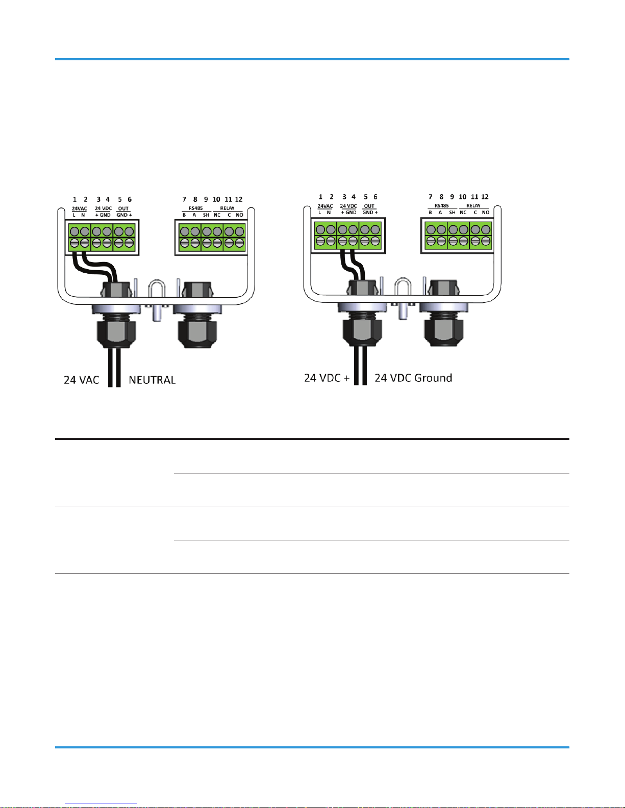
Either 24 VAC or 24 VDC may be used to power the ART. Connect wiring to the appropriate
terminal locations. Use 2 wires between 14 and 22 AWG.
POWER OPTION PIN LABEL WIRING TERMINATION
24 VAC
1 L 24V AC line
2 N 24V AC neutral
24 VDC
3 + 24V DC positive
4 GND 24V DC ground
The ART must be powered by either:
• A suitable UL 60950/CSA certied power supply that is isolated from line voltage by
double insulation, or
• An appropriately rated UL listed/CSA Class 2 transformer.
Failure to comply can result in personal injury or death.
Page 30
30 © 2014 All rights reserved. Data subject to change without notice.
ART - Operation Manual Rev. 1 | 2014.02
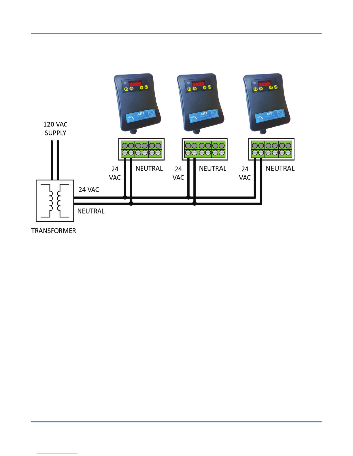
7.2.1 Maintaining Neutral Polarity
Neutral polarity must be maintained across units.
7.3 Wiring Alarm Output (Analog Signal)
The ART provides an analog output signal that is proportional to the level of gas detected.
NOTE: No jumpers or hardware switch settings are required to congure the analog output.
This is done electronically from the front panel display.
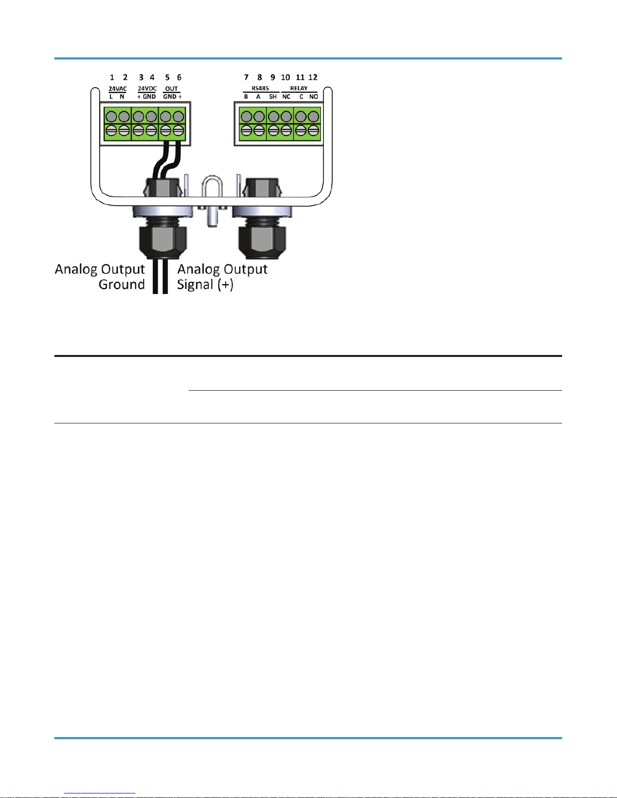
Connect two 18 to 20 AWG wires to terminal block positions 5 and 6, noting ground and
signal polarity shown in Section 7.2.1 Maintaining Neutral Polarity.
Page 31
© 2014 All rights reserved. Data subject to change without notice. 31
Rev. 1 | 2014.02 ART - Operation Manual
FUNCTION PIN WIRING TERMINATION
Analog
Output
5 Analog output ground
6 Analog output signal (+)
The type of output signal on pins 5 and 6 is programmable using the analog output type
parameter P.-03. Refer to Section 9 Setting and Conguring the Parameters for details.
7.4 Wiring Digital Alarm Output Relay
An alarm setpoint may be programmed from the front panel of the ART. When the sensed
gas level exceeds the alarm setpoint, the ART enters the alarm state. An on-board relay is
tied to the alarm state, so you may activate (or deactivate) external equipment based on
the ART’s current alarm status.
Page 32
32 © 2014 All rights reserved. Data subject to change without notice.
ART - Operation Manual Rev. 1 | 2014.02
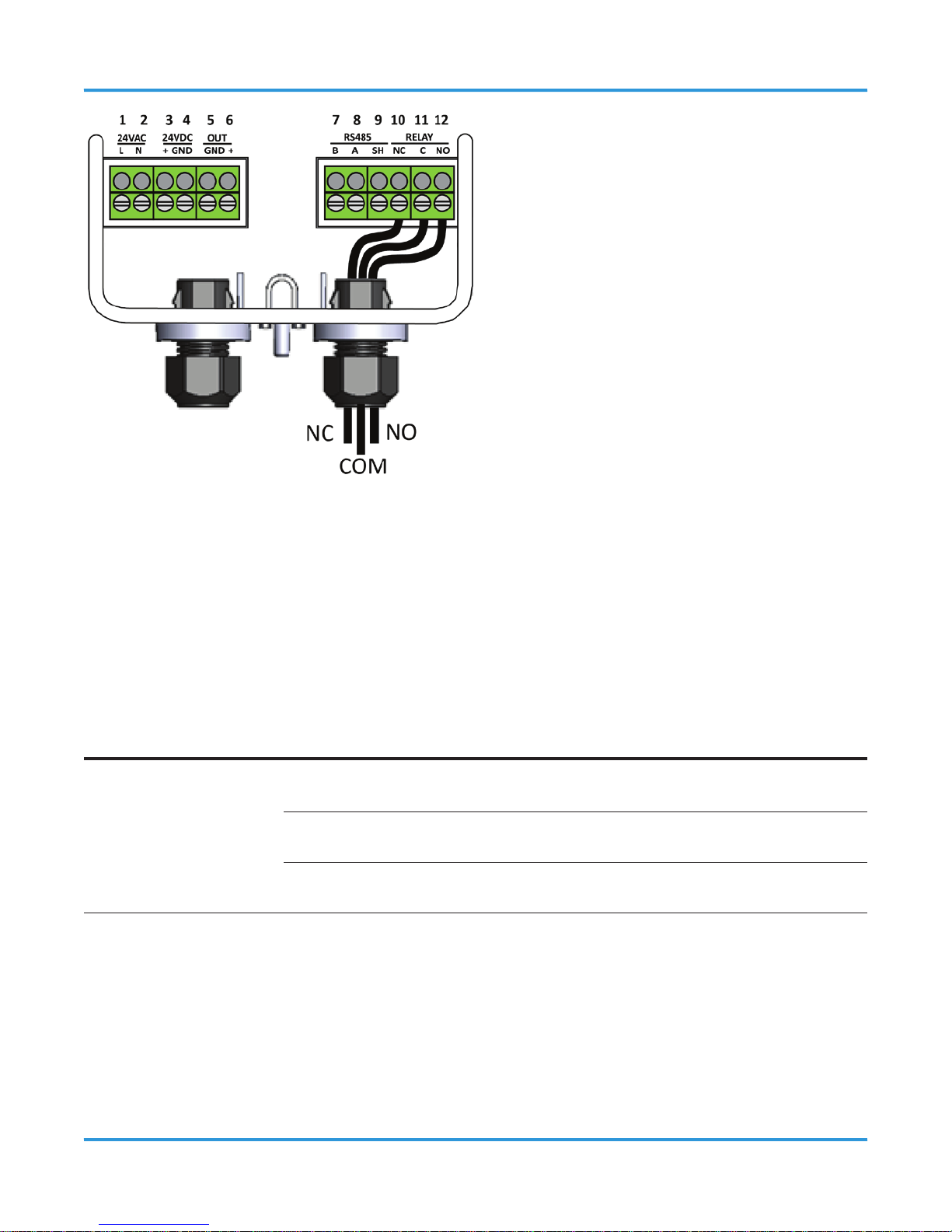
NOTE: The relay can be programed to be failsafe (normally energized). By default, the relay
is set to be normally de-energized. This can be set using parameter P-06.
Make relay connections (NO, NC, or both) using 18 to 20 AWG wires to terminal block
positions 10, 11, and 12, noting normally open, normally closed, and common connectors.
FUNCTION PIN WIRING TERMINATION
Relay (Alarm)
Output
10 Relay NC contact
11 Relay common contact
12 Relay NO contact
7.5 Modbus Network Conguration
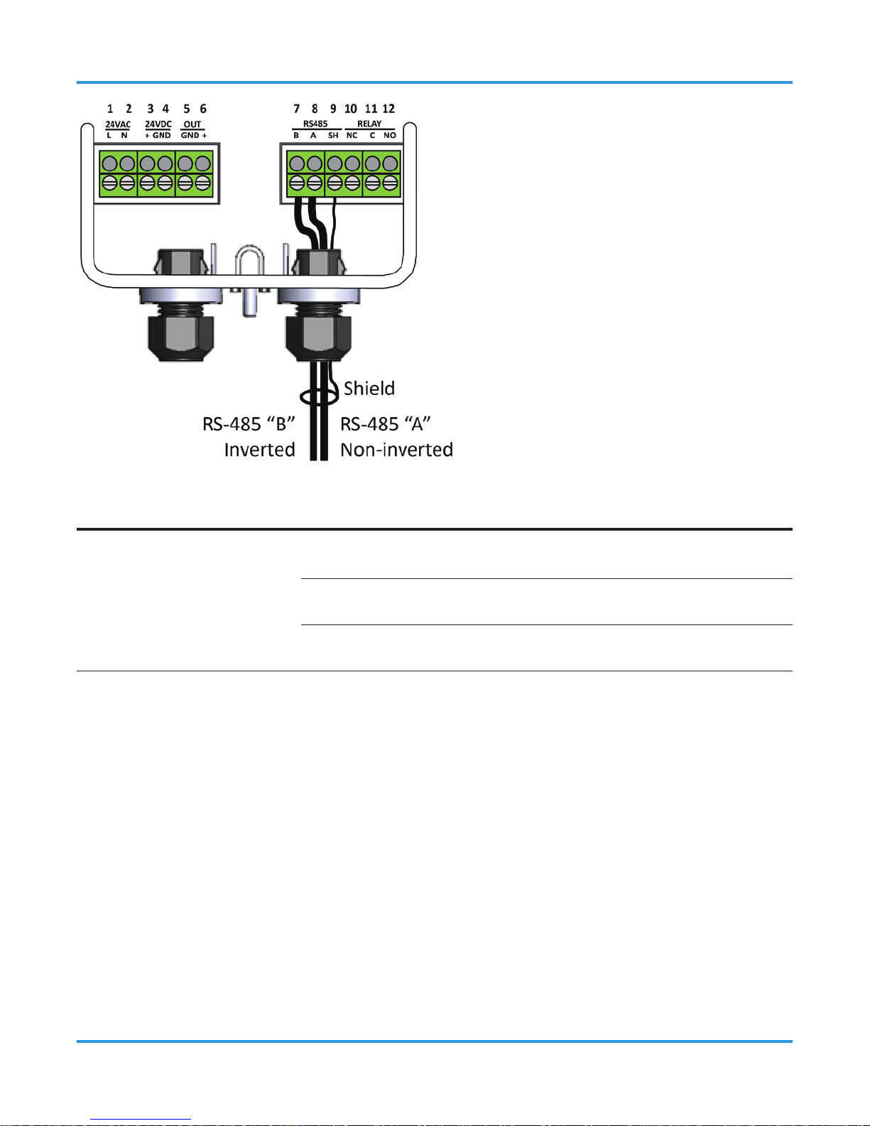
If your application includes a Modbus network, make network connections (RS-485 A and
RS-485 B) using 18 to 24 AWG shielded twisted pair wires (with 120 ohm characteristic
impedance) to terminal block positions 7 and 8, noting inverted B (-) and non-inverted A
(+) signal connectors.
Page 33
© 2014 All rights reserved. Data subject to change without notice. 33
Rev. 1 | 2014.02 ART - Operation Manual
FUNCTION PIN WIRING TERMINATION
Modbus Network
Communications
7 RS-485 “B” (inverted)
8 RS-485 “A” (non-inverted)
9 RS-485 shield
NOTE: For Modbus network communications wiring, use only 18 to 24 AWG shielded
twisted pair wire with 120 ohm characteristic impedance.
Connect the RS-485 cable shield pin 0 (board ground).
Selection of the Modbus Address and Baud Rate is completed through the gas detector
setup menu, described later. No jumpers or hardware switch settings are required to
congure the Modbus communications network. This is done electronically from the front
panel display.
Page 34

34 © 2014 All rights reserved. Data subject to change without notice.
ART - Operation Manual Rev. 1 | 2014.02
For Modbus communications with the ART, the default communications parameters are as
follows:
• Baud rate = 9,600
• Parity = no parity
• Stop bits = 1
Conrm that all devices on the Modbus communications network (including a Building
Management System) are congured similarly.
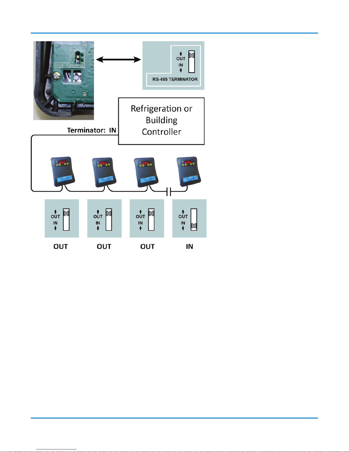
If the ART is at the end of the RS-485 network, then be sure to set the RS-485 terminator
on the printed circuit board (PCB) to IN. This applies a terminating resistor to the end of the
wires per the requirements of the RS-485 protocol. The terminator should be set to OUT for
all other installation conditions.
Be sure to enable the termination resistor on the device at each end of the network. This
includes the Building Management System (if used).
NOTE: Care should be exercised when changing the terminator switch. Before powering
the gas detector, use a ne pointed device or paper clip to slide the switch position. Do
not apply force to the switch or push on the switch with any device. The switch changes
position up and down along the access slot direction.
Page 35
© 2014 All rights reserved. Data subject to change without notice. 35
Rev. 1 | 2014.02 ART - Operation Manual
7.6 Conclusion
Once the base is mounted and all wiring is complete, align the gas detector housing and
press it onto the base. The gas detector will snap into position, completing all electrical
connections. Ensure the top and bottom snap locks are engaged.
NOTES:
• If the right cable gland was not needed during installation and wiring, be sure to
install the blanking plug.
• Do not apply caulking or other material around the gas detector base. The gas detector
relies on air exchange through the spaces between the base and the gas detector
housing. Do not obstruct the small gap around the housing and the base with any
material.
Page 36

36 © 2014 All rights reserved. Data subject to change without notice.
ART - Operation Manual Rev. 1 | 2014.02
8 OPERATION AND STABILIZATION
8.1 Power Up and Warm-up
On powering up, the ART will sense for the presence of gas after an initial warm-up period
of 2 to 5 minutes. The green LED will ash at a 1 second interval during the warm-up.
8.2 Stabilization
It is vital when rst installing the gas detector that it warms up in an atmosphere that is
known not to contain any background concentrations of refrigerant.
8.3 Perform a Manual Zero
After the gas detector stabilizes, the power LED stops ashing and is lit continuously. CETCI
recommends manually zeroing the ART after a 1-hour stabilization period.
To manually zero the gas detector, press and hold the UP and DOWN buttons simultaneously
for 5 seconds. The gas detector will beep and the display will show “ZERO” when zeroing is
complete. The display will show FAIL if the temperature is changing too quickly or there is
an active alarm condition.
NOTES:
• Manual zero should be performed in the environment of operation and at the typical
operating temperature.
• Subsequent manual zeroes may be performed, provided the atmosphere around
the gas detector is free of all background concentrations of refrigerant. Clean air or
nitrogen applied to the calibration port for ve minutes may be used to ensure the
gas detector is clear of all background gas. Re-zeroing with background refrigerant
present will cause the gas detector to report incorrect readings.
Page 37

© 2014 All rights reserved. Data subject to change without notice. 37
Rev. 1 | 2014.02 ART - Operation Manual
8.4 Behavior During Alarm Conditions
The following occurs during an alarm condition:
ITEM BEHAVIOUR DURING ALARM STATE
Green LED ON (solid)
Display
ON (blinks), reports detected ppm concentration
Audible Alarm
ON (if enabled and after programmed delay expires)
Relay Output
Activates (after any programmed delay expires)
Analog Output
Changes proportionally with gas concentration (as congured)
Modbus Registers
Registers indicate the alarm condition, ppm concentration, etc.
NOTE: The alarm feature includes a 20% dead band to prevent alarm ‘chatter’ if the
concentration hovers near the alarm set point. Once the alarm has been triggered it will
remain latched until the concentration drops below 80% of the alarm setpoint.
8.5 Gas Detector Faults
8.5.1 Overview
There are two levels of faults monitoring built into the ART gas detector:
• Non-critical
• Critical
8.5.2 Non-Critical Faults
Non-critical faults typically recover by allowing the gas detector surroundings to stabilize,
for example, after a defrost cycle. The gas detector continues to monitor its surroundings
during non-critical faults, but may report inaccurate readings.
Page 38

38 © 2014 All rights reserved. Data subject to change without notice.
ART - Operation Manual Rev. 1 | 2014.02
The following occurs when a non-critical fault condition exists:
ITEM BEHAVIOUR DURING ALARM STATE
Green LED ON (solid)
Display
Shows the appropriate fault code
Analog Output
Operates normally
Modbus Registers
Modbus registers indicate the fault
8.5.3 Critical Faults
Critical faults may indicate an unrecoverable condition. Please refer to Section 13
Troubleshooting for more information. The following occurs when a critical fault condition
exists:
ITEM BEHAVIOUR DURING ALARM STATE
Green LED OFF (indicating the gas detector is o-line)
Display
Shows the appropriate fault code
Analog Output
4 - 20 mA output Changes to 2 mA
1 - 5V output Changes to 0.5V
2 - 10V output Changes to 1.0V
Modbus Registers
Modbus registers indicate the fault
Page 39
© 2014 All rights reserved. Data subject to change without notice. 39
Rev. 1 | 2014.02 ART - Operation Manual
9 SETTING AND CONFIGURING THE
PARAMETERS
9.1 User Interface Overview
The ART Gas Detector is congured through the built-in menu system. Once mounting is
complete, attach the gas detector to the base and apply power.
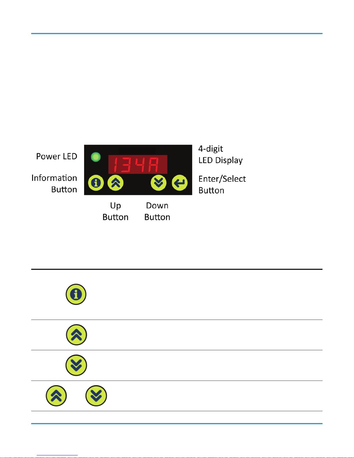
The user interface consists of four pushbuttons, a four digit LED numeric display, and a
power LED. When the display is o, press any button to wake the display for 10 seconds.
Buttons functions:
BUTTON BEHAVIOR DURING ALARM STATE
Used to access the parameter list. Used to back up one
level without writing to memory when the parameter list is
active. Used to mute the audible alarm for the time period
congured in parameter P.-12.
Used to increment the value or parameter displayed.
Used to decrement the value or parameter displayed.
+
When pressed together and held for 5 seconds, this key
combination manually zeroes the gas detector.
Page 40
40 © 2014 All rights reserved. Data subject to change without notice.
ART - Operation Manual Rev. 1 | 2014.02
Saves the currently displayed parameter to memory.
9.2 Setting Parameters
9.2.1 Overview
Press and hold the information button (i) for 5 seconds to activate the parameter list.
Each parameter is shown in turn by using the UP or DOWN buttons. The parameter is shown
as P.-XX, with XX being the parameter value. Pressing Enter while a parameter is displayed
allows the attributes of the parameter to be set. Each Parameter has its own attributes, as
shown in the table below. Set the attributes as desired, and then press Enter to save the
setting.
9.2.2 Conguring Parameters
PARAMETER DESCRIPTION
Maintenance Mode
Sets gas detector to oine mode for 30 minutes.
00 Gas detector is online, with normal response to its
surroundings (default)
01 Gas detector is oine and suppresses all outputs. Display
reads “oFFL” (oine) during 30 minute timeout.
Alarm Set Point
Sets desired ppm value (range 75 to 3,500 ppm) above which alarm
occurs. Use UP or DOWN buttons. For faster “coarse” adjustment,
hold either button to sweep through the adjustment range quickly.
Default set point is 250 ppm for all gases except R123 where the
default is 100 ppm.
Page 41
© 2014 All rights reserved. Data subject to change without notice. 41
Rev. 1 | 2014.02 ART - Operation Manual
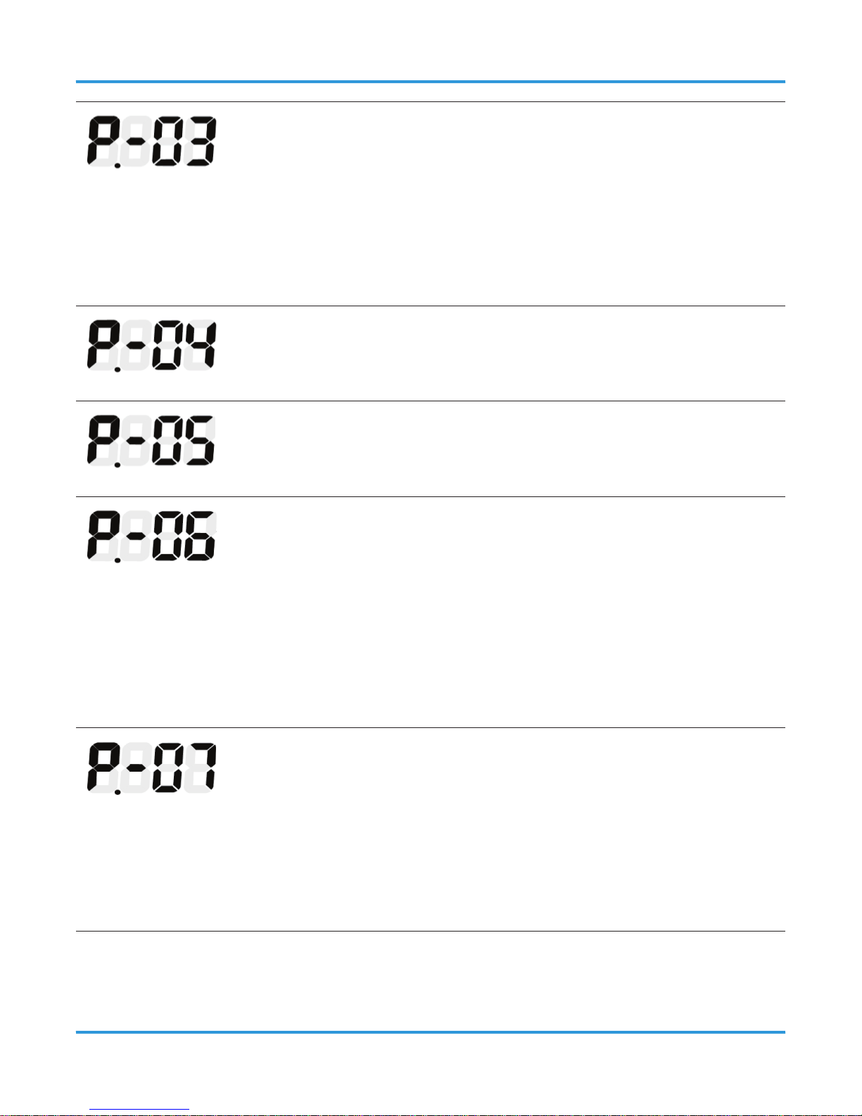
Analog Output Type
Selects output type:
00 Selects 0-5 V
01 Selects 1-5 V
02 Selects 0-10 V
03 Selects 2-10 V
04 Selects 4-20 mA (default)
Alarm ON Delays
Sets the ON delay time (0-15 minutes) for the alarm output signals
(relay, Modbus). The default delay is 0 minutes.
Alarm OFF Delays
Sets the OFF delay time for the alarm output signals (relay, Modbus)
in minutes (0-15). The default delay is 0 minutes.
Relay Contact Behavior (Failsafe Mode)
Sets the default relay power state so that power loss can be detected.
The behavior of the relay changes from energizing when an alarm
condition occurs (default) to energizing at power up (Failsafe). In
both cases the relay changes state when an alarm occurs, failsafe is
simply inverted. This allows power failures to be detected as alarms.
00 NO (default mode)
01 Failsafe mode
Relay Latching
Controls the relay latching behavior.
00 OFF (default). Relay does not latch and resets once the alarm
condition is removed.
01 ON. Relay remains latched; reset by BMS command over
RS-485 or by pressing and holding the ENTER button for 5
seconds.
Page 42

42 © 2014 All rights reserved. Data subject to change without notice.
ART - Operation Manual Rev. 1 | 2014.02
Audible Alarm
The units have an internal audible alarm. You can disable this, but
the default setting is “enabled” in compliance with EN378.
00 OFF
01 ON (default)
Display Mode
The display can be turned on by using this parameter. When set
to ON the display never shuts o (all operating modes). When ON
the display shows the current gas concentration (or 0 if below the
squelch). Note that P.-09 is disabled if P.-19=0.
00 OFF during normal operation when the ppm value is below
the alarm set point
01 ON (default)
In either case, the display will blink the measured ppm value during an
alarm state.
RS485 Node Address
Sets the RS-485 node address (0001 to 0255).
Page 43

© 2014 All rights reserved. Data subject to change without notice. 43
Rev. 1 | 2014.02 ART - Operation Manual
Gas Groups / Specic Gas Selection
Selects either gas group number for broadband operation or specic
gas name for gas-specic mode.
Broadband: Select from 3 groups of gases:
1 R134a, R404a, R407a, R407c, R407f, R427a,
R507
2 R422a, R422d HFO1234YF, and HFO1234Ze
3 R22 (by itself)
Specic Gas: The actual refrigerant name is shown. Select the
appropriate refrigerant.
NOTE: Gas-specic detectors are factory calibrated to a single
refrigerant using specialized manufacturing equipment. If another
refrigerant is selected which diers from the factory calibrated
setting, the built in calibration no longer applies. Further
improvement in detector accuracy may be gained by applying
calibration gas containing the newly selected refrigerant and
adjusting the gas detector reading to match (see Parameter P.-17).
Buzzer Mute Time
Sets a time (0-59 minutes) during which the active buzzer remains
muted:
- after the “I” button is pressed, or
- after Modbus register 4000 is set to 0
Baud Band
Sets the baud rate for Modbus (RS-485) communications.
00 9,600 baud (default)
01 19,200 baud
Page 44

44 © 2014 All rights reserved. Data subject to change without notice.
ART - Operation Manual Rev. 1 | 2014.02
Stop Bits
Sets the number of stop bits required to match the controlling communications equipment (e.g., building management system, etc.).
01 1 stop bit (default)
02 2 stop bits
Parity
Sets Modbus parity option.
00 None (default)
01 Odd parity
02 Even parity
Analog Output Scaling
Allows the user to select the full-scale ppm value that represents
maximum analog output (e.g., 20 mA) for scaling the analog output.
Adjustment range is from 100 to 3,500 ppm. Default = 3,500 ppm.
(The setting cannot be adjusted above 3,500.)
Use the Up and DOWN buttons to set the desired full scale value. All
outputs will be scaled to the indicated full scale value.
NOTES:
• Alarm values are not scaled, but are absolute values. Setting
a smaller full scale does not correspondingly scale the alarm
setting.
• When the ppm level is greater than the programmed analog
output Full Scale ppm (P.-16), the analog output will go to a
10% over range state (indicating that the concentration is too
high for the analog output to achieve). For example, for a 1-5
V setting the analog output would go to 5.5 V, for 4 20 mA it
would go to 22 mA and so on.
Page 45
© 2014 All rights reserved. Data subject to change without notice. 45
Rev. 1 | 2014.02 ART - Operation Manual
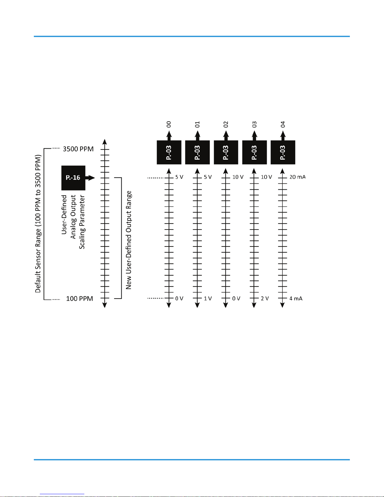
The analog output signal range is from 100 ppm to the default value of 3500 ppm, which is
scaled across the actual output range selected by the analog output type parameter P.-03.
The upper ppm limit is programmable using analog output scaling parameter P.-16. This
parameter sets the full scale ppm value creating a ppm range across which the analog
output is scaled.
Page 46

46 © 2014 All rights reserved. Data subject to change without notice.
ART - Operation Manual Rev. 1 | 2014.02
PARAMETER DESCRIPTION
Gas Test Mode
Places the gas detector in gas test mode.
00 Disabled (default)
01 Enabled
When enabled, the display continuously cycles through the
following:
- CAL is displayed briey.
- Next, the gas group number or gas type (based on product
code) is displayed.
- Then four dashes (----) are displayed.
After gas is applied and the 75 ppm squelch level is exceeded,
the live concentration replaces the four dashes. See Section 10.4
Adjustment Using Calibration Gas if using Gas Test Mode to initiate
the calibration procedure.
NOTE: To prevent false alarms, all outputs are suspended while Test
Mode is active. The only live indication is the 4-digit display. Once
the gas test mode is enabled to perform a gas test or calibration,
the unit will automatically go oine for a ten minute period after
the parameter list is exited. (This allows time for the test gas to clear
before the unit becomes active). If no activity occurs for ten minutes,
the unit exits the gas test mode.
Page 47

© 2014 All rights reserved. Data subject to change without notice. 47
Rev. 1 | 2014.02 ART - Operation Manual
Diagnostics Menu
Parameter 18 provides access to the self-diagnostic information.
The LED display shows “DIAG” until the Enter button is pressed. Use
the UP and DOWN buttons to scroll through the list of diagnostic
attributes.
A.-01 Current fault condition
A.-02 Last fault
A.-03 Days in service
A.-04 Days since last adjust/test
A.-05-A.-07 Factory Use Only
A.-08 Detector temperature in
o
C
A.-09 Temperature rate of change
A.-10-A.-17 Factory Use Only
To aid in troubleshooting, the operator may choose to reset the
gas detector to its default state by holding both the UP and DOWN
buttons for 5 seconds while in the Diagnostics Menu. All settings,
including the alarm set point, gas adjustments, the selected gas
curve, calibration data, the Modbus address, etc. revert to specic
default values after a reset.
IMPORTANT: Calibrations on either gas-specic or broadband
models are lost after a reset. This returns the gas detector to an
uncalibrated condition. See Parameter P.-17 for information on how
to recalibrate the gas detector.
Refer to Section 13 Troubleshooting for a complete list of codes and
details on the reset option.
Page 48

48 © 2014 All rights reserved. Data subject to change without notice.
ART - Operation Manual Rev. 1 | 2014.02
Response Filtering
This parameter is used to turn ltered output ON (01) or OFF (00).
The default setting is ON (01). The Modbus and analog output are
ltered so that responses below 75 ppm are squelched. If the display
mode (P.-09) is set to ON (01) the display shows 0 for any signal level
below 75 ppm.
Some installations may wish to monitor the small analog output
changes that may be created by the detector environment. Turning
ltering OFF (00) allows these small variations around the minimum
analog output (e.g., 4 mA, 1V, etc.) to be transmitted via Modbus
and the analog output terminals.
NOTES:
• The detector display is OFF when ltering is OFF (P.-09 is
disabled).
• Whenever ltering is OFF the detector display will turn ON for
10 minutes if the detector is re-zeroed (see Section 8.3 Perform
Manual Zero). This is intended to aid maintenance testing. The
analog outputs continue to transmit the full, unltered range,
and the alarm set point remains active.
9.3 Completing Setup
To complete the setup after all parameters are set as needed, simply press and hold the
information button (i) for 5 seconds to exit the Parameter list. The gas detector is now
actively monitoring its surroundings.
NOTE: If no buttons are pressed for 2 minutes, the ART exits setup mode automatically.
Page 49

© 2014 All rights reserved. Data subject to change without notice. 49
Rev. 1 | 2014.02 ART - Operation Manual
10 FUNCTIONAL TESTS AND GAS
ADJUSTMENTS
10.1 Warnings and Cautions
To comply with the requirements of EN378 and the European F-GAS regulation, gas
detectors must be tested annually. However, local regulations may specify the nature and
frequency of this test. Check local regulations on calibration or testing requirements.
The ART contains sensitive electronic components that can be easily damaged. Neither
touch nor disturb any of these components.
CETCI recommends annual checks and adjustment using calibration gas. Calibration gas
adjustment frequency may be extended based on application, but should never exceed 2
years.
In applications where life safety is critical, calibration gas adjustment should be done
quarterly (every 3 months) or on a more frequent basis. CETCI is not responsible for setting
safety practices and policies. Safe work procedures including calibration policies are best
determined by company policy, industry standards, and local codes.
Failure to test or adjust the unit in accordance with applicable instructions and with
industry guidelines may result in serious injury or death. The manufacturer is not liable
for any loss, injury, or damage arising from improper testing, incorrect adjustment, or
inappropriate use of the unit.
Before testing the gas detectors on-site, the ART must have been powered up and allowed
to stabilize.
After initial installation, the ART should be gas tested to ensure proper operation.
The testing and/or adjustment of the unit must be carried out by a suitably qualied
technician, and must be done:
• In accordance with this manual
Page 50

50 © 2014 All rights reserved. Data subject to change without notice.
ART - Operation Manual Rev. 1 | 2014.02
• In compliance with locally applicable guidelines and regulations
Qualied operators of the unit should be aware of the regulations and standards set
down by the industry/country for the testing or calibration of this unit. This manual is
only intended as a guide and, insofar as permitted by law, the manufacturer accepts no
responsibility for the calibration, testing, or operation of this unit.
The frequency and nature of testing or calibration may be determined by local regulation
or standards.
EN378 and the F-GAS Regulation require an annual check in accordance with the
manufacturer’s recommendation.
10.2 Bump Test vs Adjusting Detector Response
There are two concepts that need to be dierentiated:
• Bump test
• Gas detector response adjustment
A bump test exposes the gas detector to a gas. The operator then observes the gas
detector’s response to the gas. The objectives are two-fold:
• Establishes if the gas detector is reacting to the gas
• Determines if all of the detector outputs are working correctly
There are two types of bump tests:
• Quantied - A known concentration of gas is used.
• Non-quantied - A gas of unknown concentration is used (should not exceed two
times the sensor range, preferable within the sensors range of 3500 ppm).
Adjusting gas detector response exposes the gas detector to a calibration gas as well (like
a quantied bump test), but additionally sets the actual gas detector response level (via
Parameter P. 17) to ensure that the gas detector activates at the specied gas concentration.
Page 51

© 2014 All rights reserved. Data subject to change without notice. 51
Rev. 1 | 2014.02 ART - Operation Manual
Refer to the following Sections below for additional information on bump testing and gas
detector response adjustment.
CAUTION: Before you carry out the test or adjustment:
• Advise occupants, plant operators, and supervisors.
• Check if the gas detector is connected to external systems such as sprinkler systems,
plant shut down, external sirens and beacons, ventilation, etc. and disconnect as
instructed by the customer.
• For bump test or calibration the ART should be powered up and fully stabilized as per
Section 8 Operation and Stabilization.
10.3 Bump Testing
NOTE: Notify others that testing is underway. During bump testing the alarm outputs are
active, and will trigger whatever response is intended. It is the operator’s responsibility to
ensure that such actions are acceptable and can be performed safely.
After installation and parameter setup (see Section 9 Conguration), the units should
be bump tested. Expose the gas detector to test gas. The gas selected should be a high
enough concentration to put the system into alarm and light the LED display.
With a bump test you can see the functions of the gas detector:
• The LED display will light and show the detected ppm concentration once the alarm set
point is reached
• The relay and audible alarm will function as congured including any delays set (ON
or OFF).
• The output (0 - 10 V, for example) will show the gas level
Ideally bump tests are conducted on-site in a clean air atmosphere.
Step 1:
Remove the splash guard accessory if one is used.
Page 52
52 © 2014 All rights reserved. Data subject to change without notice.
ART - Operation Manual Rev. 1 | 2014.02
Step 2:
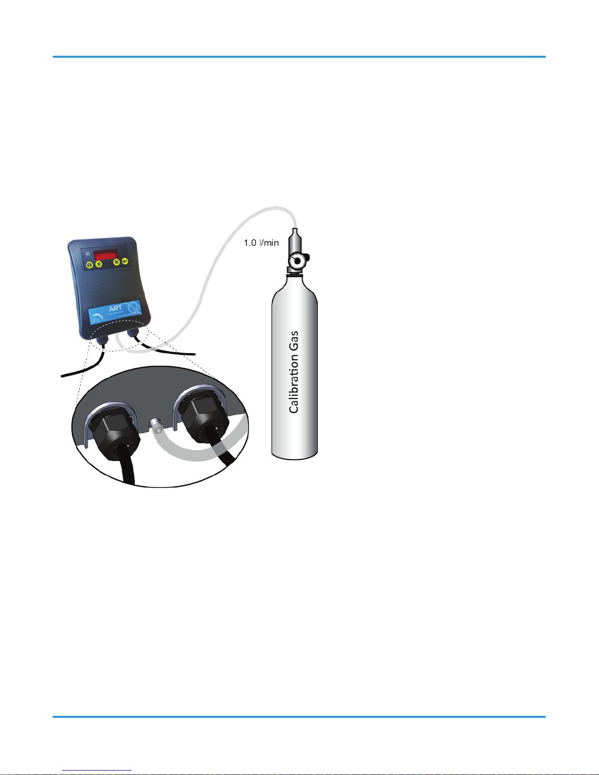
Connect the regulator to the test gas port using 3mm or 1/8” inside diameter tubing (see
below).
Step 3:
Expose the gas detector to gas from the cylinder. Monitor the LED display reading. Refer to
Section 4.1 Technical Specications for acceptance criteria.
10.4 Adjustment Using Calibration Gas
Every ART gas detector is calibrated in a chamber by true diusion method prior to leaving
our facility. This method more closely emulates actual “real world” conditions. Field
calibration using gas cylinder, regulator and hose directing span gas into the sensor may
result in slightly higher readings. It is important to note that the type of gas mixture, how
old the gas is and what temperature it has been stored at will also aect repeatability
during eld calibration.
Adjustment using calibration gas requires a gas cylinder with the appropriate gas and
concentration. Note that CETCI oers a calibration kit that consists of a calibration gas
Page 53

© 2014 All rights reserved. Data subject to change without notice. 53
Rev. 1 | 2014.02 ART - Operation Manual
cylinder and a ow regulation valve with exible non-absorbent tubing.
If an inappropriate concentration of span gas is applied during calibration, calibration may
succeed but it does not mean the equipment has been calibrated properly. CETCI is not
responsible for improperly calibrated detectors. Follow manual instructions carefully.
NOTE: For improved accuracy and response, the gas detector should be protected from
excess drafts while performing the adjustment. Excess air circulation may dilute the applied
calibration gas and lead to lower than expected response.
Step 1:
Connect the regulator to the test gas port using 3mm or 1/8” inside diameter tubing.
Step 2:
Enable Parameter P.-17 Gas Test Mode (see Section 9 Conguration). When enabled, the
display continuously cycles through the following:
• CAL is displayed briey.
• Next, the gas group number or gas type (based on product code) is displayed.
• Then four dashes (----) are displayed.
After gas is applied and the 75 ppm squelch level is exceeded, the live concentration
replaces the four dashes.
NOTE: The analog outputs, relay activity, and RS-485 ppm reporting are suspended in Gas
Test Mode to prevent false alarms.
Step 3:
Expose the gas detector to gas from the cylinder. Monitor the 4 digit LED display reading.
Step 4:
Wait for the ppm reading to stabilize. This should take approximately 4-6 minutes. Minor
changes (less than 5 ppm in 10 seconds) are considered stable readings. Compare the
Page 54

54 © 2014 All rights reserved. Data subject to change without notice.
ART - Operation Manual Rev. 1 | 2014.02
response value with the calibration gas concentration.
Step 5:
Adjust the gas detector displayed value by using the UP or DOWN buttons to increase or
decrease the value shown. Adjust until the reading is within ± 2% of the calibration gas.
For example, if the calibration gas is 1000 ppm, the gas detector is adjusted properly when
the displayed reading is between 980 and 1,020 ppm.
Step 6:
Press the Enter button to store the new adjustment. Turn o the calibration gas and remove
the tubing from the calibration port.
Step 7 :
If no further changes to the other parameters are required, press and hold the (i) button
for 5 seconds to exit the Parameter list. Upon exiting the Parameters list, the gas detector
will enter oine mode for a period of 10 minutes. This allows time for the calibration gas
to dissipate after testing. During oine mode, the gas detector suppresses all outputs. The
display reads “oFFL” (oine) during 10 minute timeout.
NOTE: All calibration gas mixtures have a blend tolerance. The tolerance will limit the
actual adjustment accuracy that is achievable.
11 MODBUS COMMUNICATIONS
11.1 Introduction
The ART gas detector can be congured to communicate on an RS-485 network using
Modbus-RTU protocol. Before conguring the gas detector for Modbus communications, be
sure your network connection is complete and your network termination switches are set
appropriately. Refer to Section 7 Wiring and Conguration, for details.
This section details the ART parameters that can be accessed via registers of the ModbusRTU (“Modbus”) protocol. Generally (with the exception of some of the communications
parameters), parameters you can access and/or congure from the front panel of the ART
Page 55

© 2014 All rights reserved. Data subject to change without notice. 55
Rev. 1 | 2014.02 ART - Operation Manual
can also be accessed and/or congured via a Building Management System (for example)
on the same Modbus network.
11.2 Communication Settings
There are 255 selections available to be set electronically, from addresses 1 to 255 inclusive.
Modbus data with a zero in the address eld is received by all detectors (regardless of
the address selected) to enable the master device to broadcast simultaneously to all the
detectors.
Refer to Section 4.1 Technical Specications for information on RS-485 network
communications parameters such as data bits, stop bits, etc.
11.3 Analog Input Registers
Analog input registers are read only and use function code 04.
REG DESCRIPTION RANGE UNITS P.-##
1000 Concentration gas level 0-100 % FS - -
1001
Concentration gas level 0-65, 535 ppm - -
1002
Reserved - -
1003
Full scale detector level 0-65, 535 ppm - -
1004
Alarm set-point (% full scale) 0-100 % - -
1005
Gas detector timer 0-35, 535 hours - -
1006
Node address 1-247 none P.-10
1007
Software version none - -
Page 56

56 © 2014 All rights reserved. Data subject to change without notice.
ART - Operation Manual Rev. 1 | 2014.02
1008
Reserved - -
1009
Reserved - -
1010
Reserved - -
1011
Reserved - -
1012
16-bit fault code 0-65535 none - -
11.4 Analog Output Registers
Analog output registers are readable (using function code 03) and writable (using function
code 06).
REG DESCRIPTION RANGE UNITS P.-##
2000 Alarm set point 75-3,500 ppm P.-02
2001
Alarm ON delay (Alarm ag
register 3000 is set to 1)
0-15 min P.-04
2002 Buzzer mute time 0-59 min P.-12
2003 Alarm OFF Delay 0-15 min P.-05
2004 Relay action
0=NO
1=Failsafe
none P.-06
2005 Relay latching enable
0=Disable
1=Enable
none P.-07
2006 Buzzer enable
0=Disable
1=Enable
none P.-08
Page 57

© 2014 All rights reserved. Data subject to change without notice. 57
Rev. 1 | 2014.02 ART - Operation Manual
2007 Display mode
0=OFF
1=ON
none P.-09
2008 Analog output type
0=0-5V
1=1-5V
2=0-10V
3=2-10V
4=4-20 mA
none P.-03
2009 Baud rate
0=9,600
1=19,200
none P.-13
2010 Stop bits 1 or 2 none P.-14
2011 Gas curve number
1 to 3
(broadband
unit) or gas type
(gas specic)
none P.-11
2012
Analog output full scale ppm
(R/O)
100-3,500 ppm P.-16
2013 Parity
0=None
1=Odd
2=Even
none P.-15
11.5 Input Status Flags
Input Status Flags are readable (using function code 02).
REG DESCRIPTION RANGE P.-##
3000 Alarm ag (0 or 1=Alarm) 0-1 - -
3001
Relay state (0 or 1=energized) 0-1 - -
Page 58

58 © 2014 All rights reserved. Data subject to change without notice.
ART - Operation Manual Rev. 1 | 2014.02
3002
Detector fault (0 or 1=fault) 0-1 - -
3003
Red LED state (0 or 1=ON) 0-1 - -
3004
Green LED state (0 or 1=powered ON) 0-1 - -
3005
Reserved - -
3006
Startup (0=normal operation, 1=warning) 0-1 - -
3007
Reserved - -
3008
Reserved - -
11.6 Output Status Flags
Output Status Flags are readable (using function code 01) and writable (using function code
05).
REG DESCRIPTION RANGE P.-##
4000 Buzzer ag (0 or 1=ON) 0-1 - -
4001
Test required (if operating for >1 year)
(1=requires testing)
0=Okay
1=Test
- -
Page 59
© 2014 All rights reserved. Data subject to change without notice. 59
Rev. 1 | 2014.02 ART - Operation Manual
12 REPLACEMENT PARTS AND ACCESSORIES
NOTE: All modules come ready to mount to the original mounting base provided.
12.1 Splash Guard
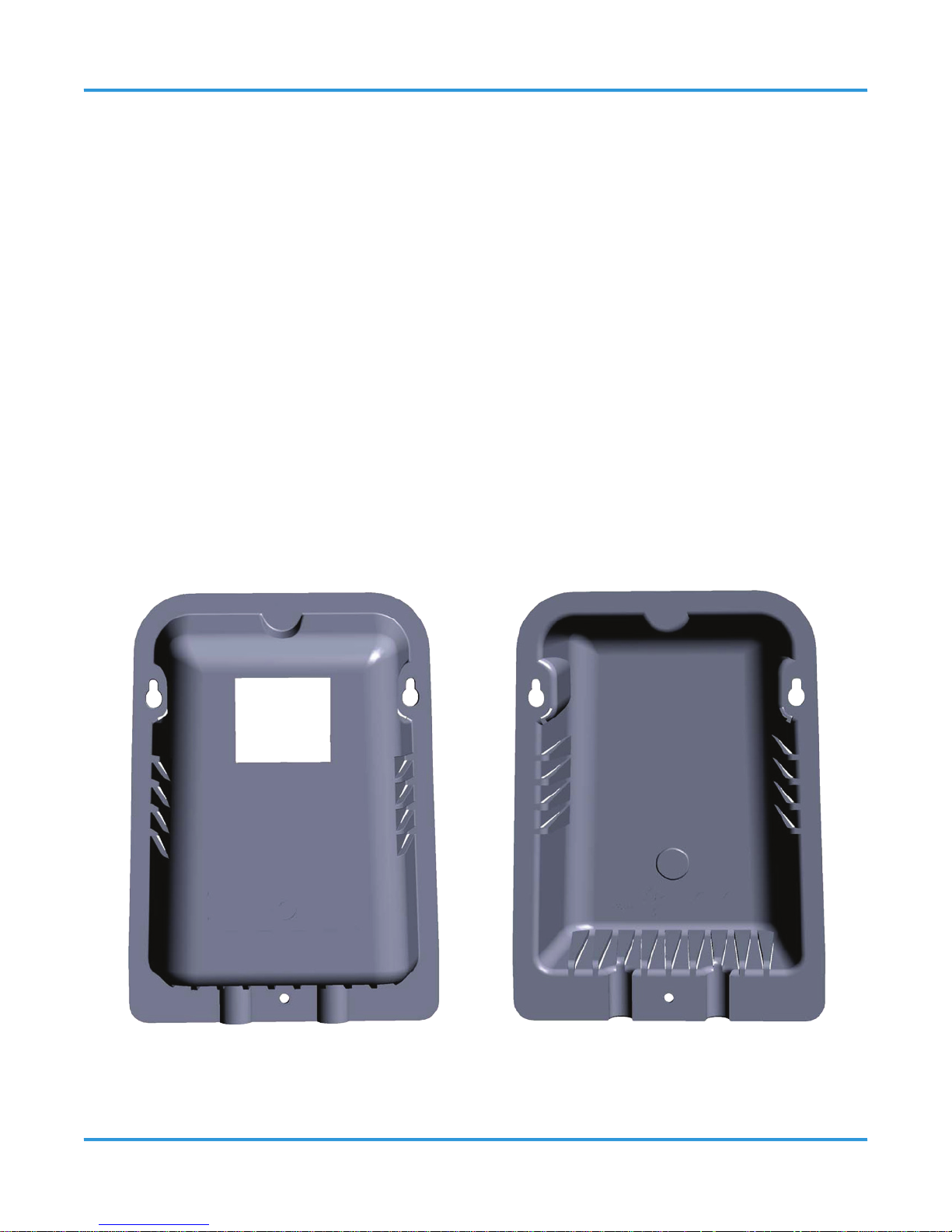
The splash guard is a protective covering that attaches to the front of the enclosure. CETCI
recommends using a splash guard to protect the detector’s sensor in wet environments or
where spray-down of equipment is a common occurrence such as meat processing rooms,
food and beverage facilities or chiller rooms.
Each splash guard comes with standard mounting hardware, instruction sheet and a
mounting template. The unit can be used on existing installations. The clear poly carbonate
housing allows for alarms to be seen throught the front window. Slots along the side and
bottom allow for gas to ow into and out of the sensor, while protecting the instruments
from water damage.
front exterior view interior view
Page 60
60 © 2014 All rights reserved. Data subject to change without notice.
ART - Operation Manual Rev. 1 | 2014.02
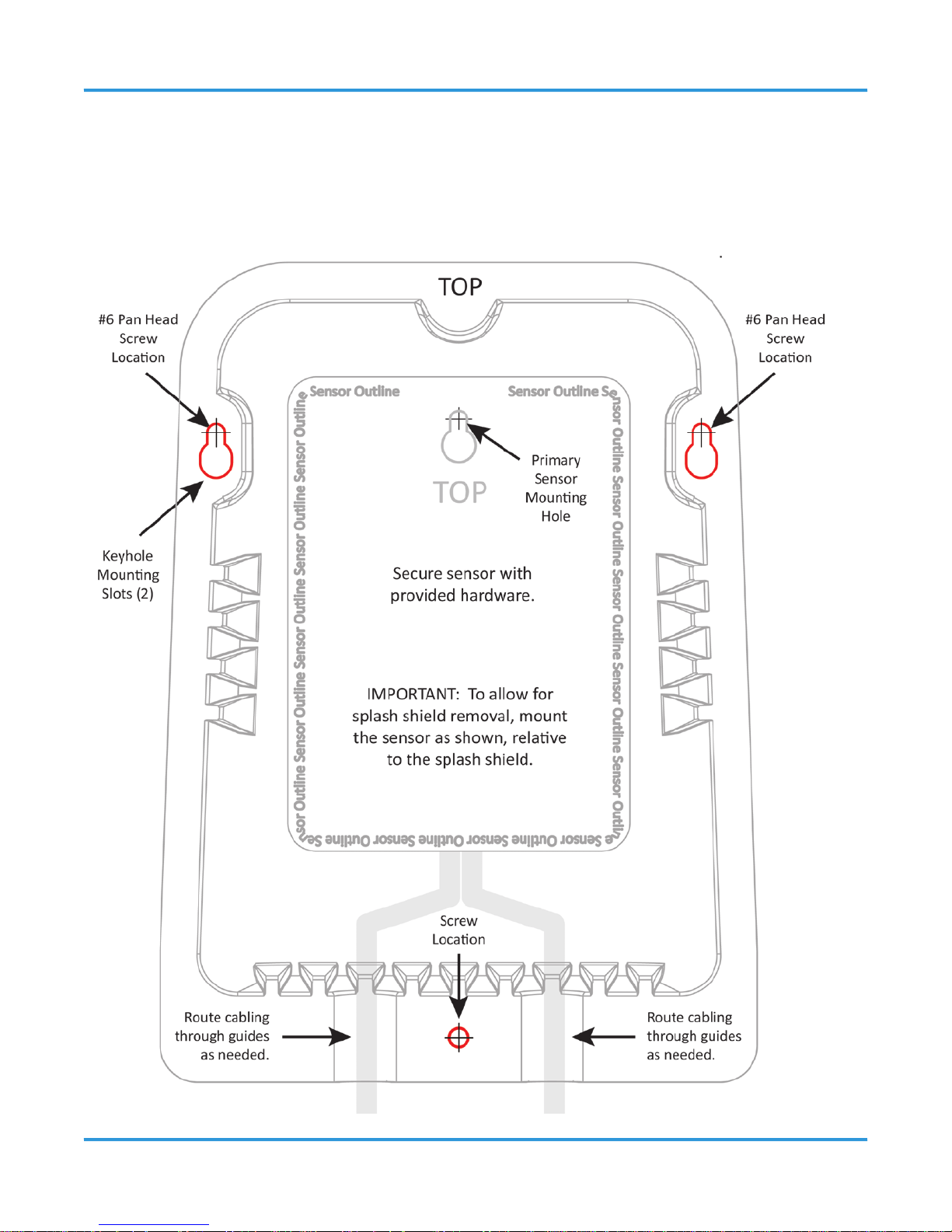
12.1.1 Splash Guard Mounting Template
The splash guard uses key-hole mounting slots designed for #6 pan head fasteners that
are provided with the splash guard. Locate the two screws in the keyholes (as shown in the
diagram below). Allow the screw heads to protrude approximately 1/8 inch (3 mm).
Page 61
© 2014 All rights reserved. Data subject to change without notice. 61
Rev. 1 | 2014.02 ART - Operation Manual
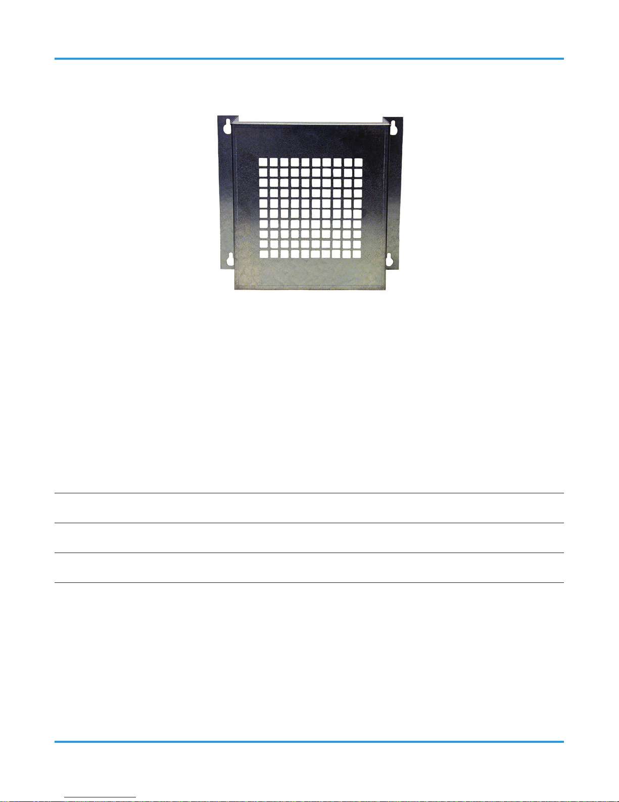
12.2 Metal Protective Guard
Part Code: SCS-8000-SPG
The metal protective guard is heavy duty metal protective grate to help protect against
abrasive damage, theft and vandalism to the transmitters. This is an added preventative on
top of the product enclosure and the splash guard (if installed).
It is made from 16-gauge galvanized steel and has ½” (13 mm) square openings in the front
to allow gas and air to ow through to the sensor. With only four slotted mounting holes,
installation and removal for gas detector servicing is easy.
Enclosure 16 gauge galvanized steel
Weight 1.7 kg (3.8 lbs)
Size 10.0” W x 9.5” H x 4.8” D (254 mm W x 241 mm H x 121 mm D)
Page 62
62 © 2014 All rights reserved. Data subject to change without notice.
ART - Operation Manual Rev. 1 | 2014.02
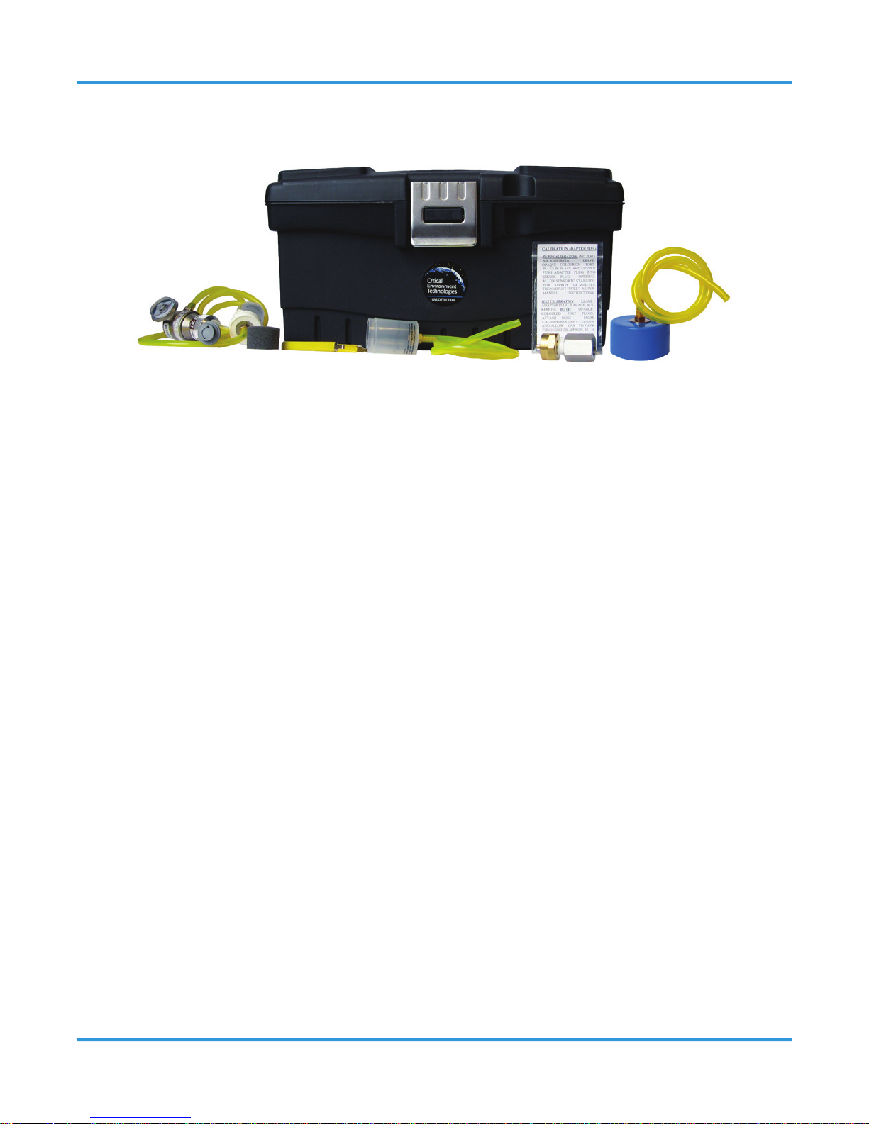
12.3 Calibration Kit
Part Code: CET-715A-CK1
Calibration kits and gases are available from the CETCI factory. Many gases are carried in
inventory but not all. Check with any CETCI authorized distributor for availability of specic
gas types. Gas cylinders cannot be shipped overseas.
13 TROUBLE SHOOTING
13.1 Fault Codes
To comply with the requirements of EN378 and the European F-GAS regulation, gas
detectors must be tested annually. However, local regulations may specify the nature and
frequency of this test.
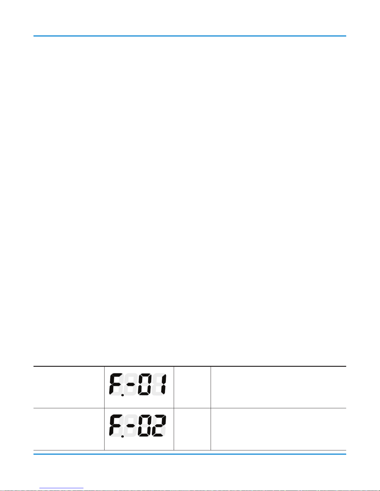
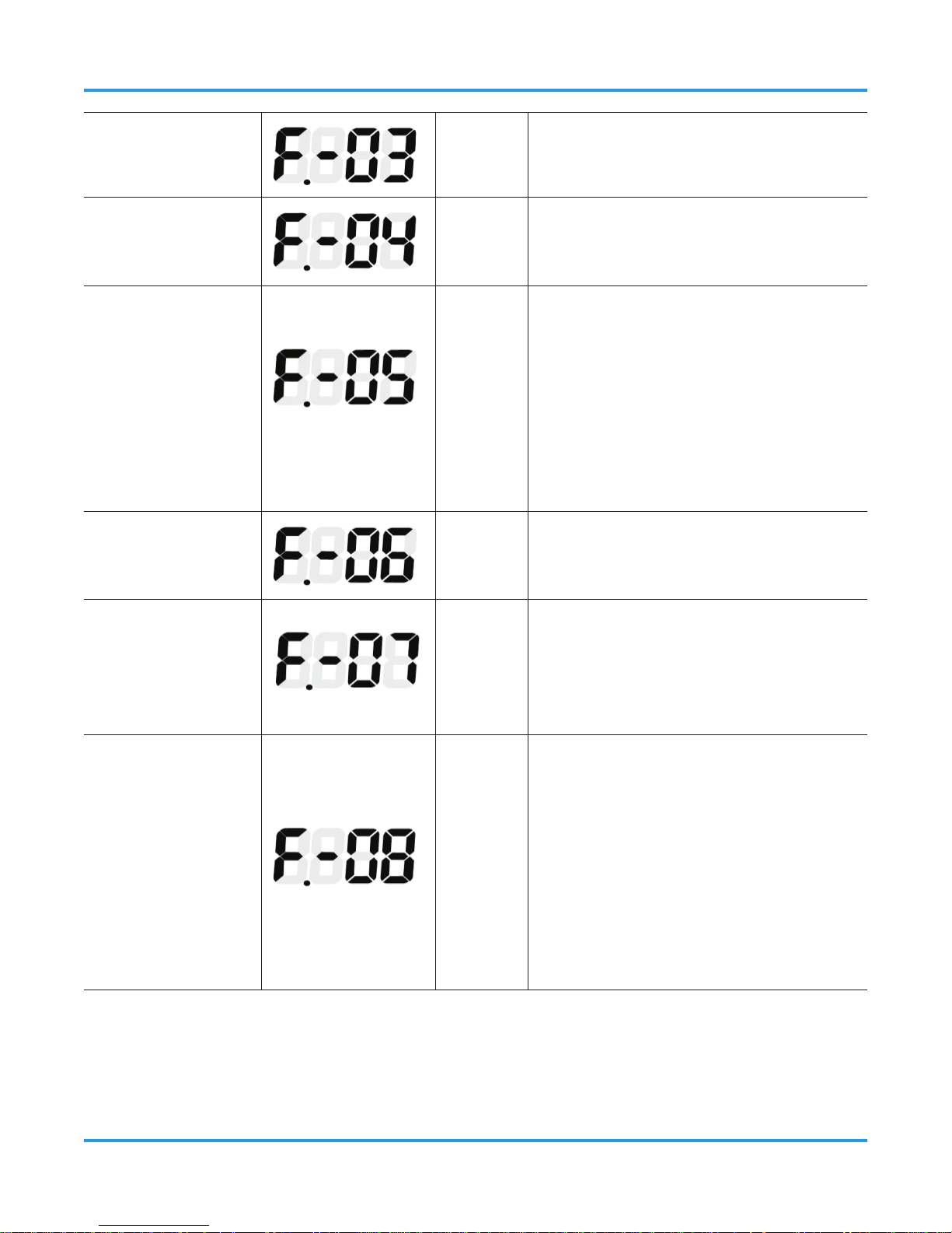
The ART features sophisticated internal status monitoring and will indicate whether a fault
condition exists, both on the front display (F.-XX, with XX being the fault number) and over
the Modbus communications network.
There are two classes of fault conditions: critical and non-critical. In general, non-critical
faults occur…
…when environmental conditions exist that are outside the product’s specied
Page 63
© 2014 All rights reserved. Data subject to change without notice. 63
Rev. 1 | 2014.02 ART - Operation Manual
operating range, or if an installation error has occurred (wrong wiring, for
example).
The gas detector will typically continue to monitor its surroundings (except for fault F.-08),
and may report inaccurate readings and false alarms.
Correcting non-critical faults is a matter of waiting for the environmental conditions to
return to a more typical condition, correcting wiring mistakes, or in some cases, relocating
the gas detector. For example, placing the gas detector near a forced air heater may cause
temperature faults. The non-critical fault range is F.-01 to F.-08. Critical faults indicate…
…a functional problem that results in the gas detector no longer monitoring its
surroundings for refrigerant.
The fault number is displayed and the power LED is turned o, indicating that the gas
detector is oine. The critical fault range is F.-09 to F.-16. If any of these faults occur,
rst try to clear the faults by cycling power to the sensor. The easiest way to do this is by
removing the sensor from the base and reattaching. If the fault returns after cycling power,
the gas detector should be removed from service and replaced.
Additionally, the faults are stored as a hex code number and can be accessed in the
Diagnostics menu P.-18. Refer to Diagnostics Attributes P.-18 in Section 13.2 for additional
information.
DESCRIPTION FAULT CODE
HEX
CODE
POSSIBLE CAUSES
Gas Detector
Temperature
Fault
0x0001
Gas Detector temperature reports
> 55° C or < -35° C.
Gas Detector
Temperature Rate
of Change Fault
0x0002
Temperature rate of change exceeds
~1°C/min for more than 15 minutes.
Page 64
64 © 2014 All rights reserved. Data subject to change without notice.
ART - Operation Manual Rev. 1 | 2014.02
RS485 RX Fault 0x0004 Message too long for receive buer.
RS485 CRC Fault
0x0008
Transmission is corrupted (computed
CRC doesn’t match transmitted CRC).
Open Loop Fault
0x0010
Possible wiring, connection, and/
or termination issue exists. When
analog output type is 4 20ma
and loop is open, use 18-24 AWG
shielded twisted pair with 120
ohm characteristic impedance for
Modbus connections.
Modbus Fault
0x0020
Modbus message was truncated or
timed out early.
PPM Over-range
Fault
0x0040
ppm exceeds 9,999. This may
indicate a very large gross leak. If
no leak is present, it indicates a gas
detector error.
Input Voltage
Fault
0x0080
Input supply power to the ART is out
of range (i.e., 24V ±20%).
IMPORTANT: If this fault is active,
the gas detector is oine and not
monitoring. Correct the input
supply voltage to restore normal
operation.
Page 65
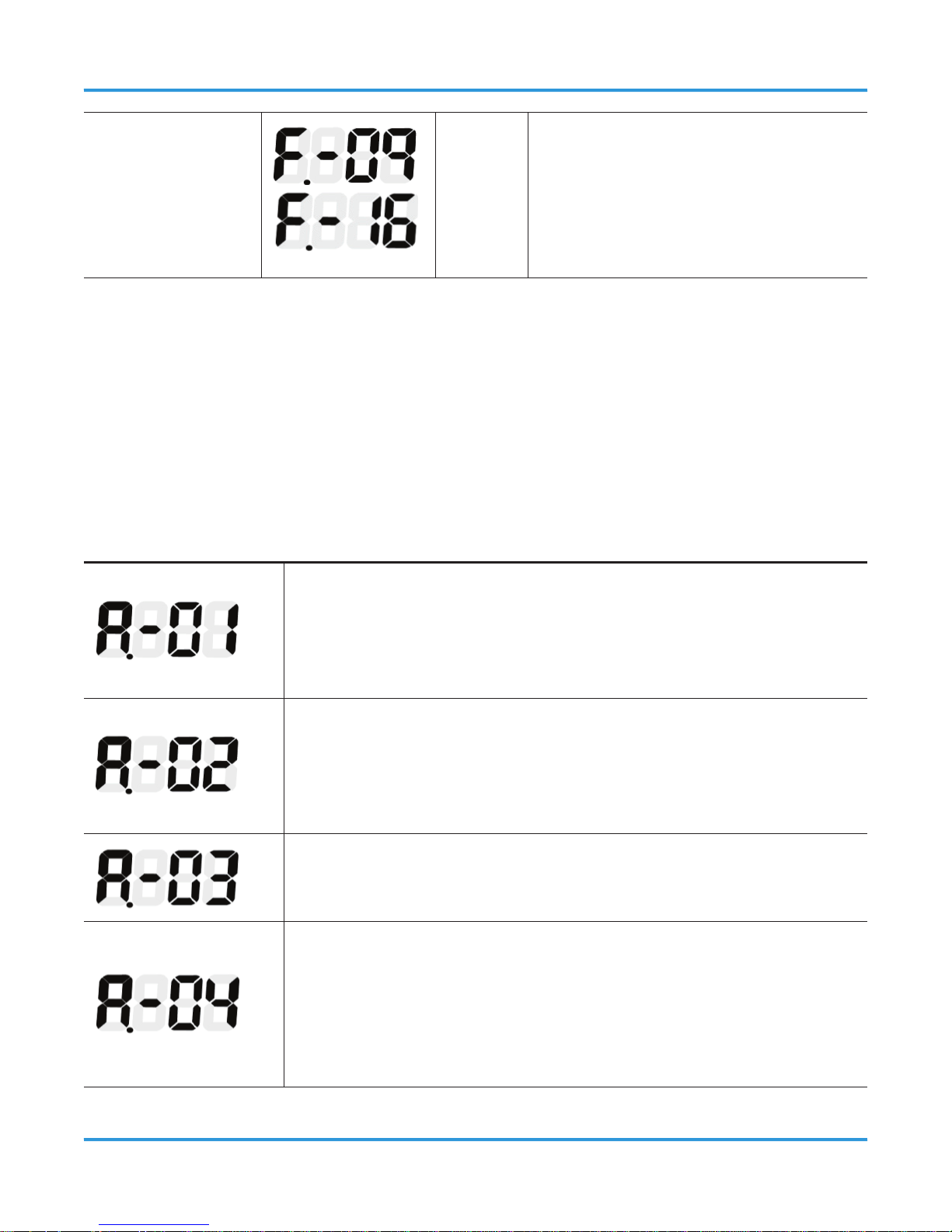
© 2014 All rights reserved. Data subject to change without notice. 65
Rev. 1 | 2014.02 ART - Operation Manual
Critical Faults
Critical fault. Cycle power to
the sensor and see of the fault
clears. If not, the gas detector
should be removed from service
and replaced.
13.2 Diagnostic Attributes (P.-18)
Use this option to review the built-in diagnostic attributes. Access the parameter list (see
Section 9 Setting and Conguring the Parameters) and select P.-18. Press the Enter button to
access the diagnostics, and then use the UP or DOWN button to select each attribute. The
following information is available.
ATTRIBUTE DESCRIPTION
Displays the current fault condition code in hex format:
0000 = no faults are active
XXXX = HEX number
See Section 13.1 Fault Codes for the HEX format cross reference.
Displays a hex format code that corresponds to any faults that
occurred since the internal fault record was last erased. See
Section 13.1 Fault Codes for the HEX format cross reference. The
records may be erased by pressing the ENTER button.
Displays the number of days that the ART has been in service.
The value of this attribute rolls over after 9999.
Displays the elapsed time (in days) from the last gas adjustment
or test. This value is automatically reset to 0000 after completing
a gas adjustment via Test Mode P.-17. (Note that the new
adjustment is stored using the Enter button.) The value may be
reset to 0000 by pressing the ENTER button.
Page 66
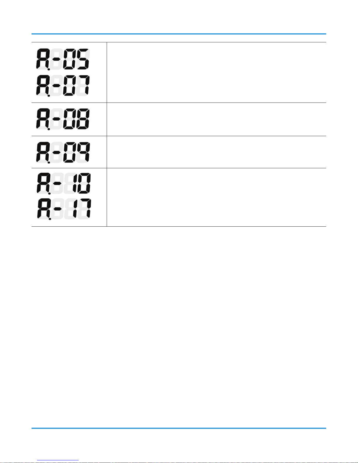
66 © 2014 All rights reserved. Data subject to change without notice.
ART - Operation Manual Rev. 1 | 2014.02
Reserved
Displays the sensor temperature in °C.
Displays the sensor’s approximate rate of temperature change per
half minute interval (°C change over 30 seconds).
Reserved
13.3 Resetting to Default Values
The gas detector may be reset to its default state, if needed, to aid in troubleshooting. All
settings, including alarm setpoint, gas adjustments, selected gas curve, calibration data,
Modbus address, etc. revert to specic default values after a reset. The broadband sensor
option resets to gas group 1. Gas specic options are reset to the R134a gas curve.
NOTE: Calibrations on either gas-specic or broadband models are lost after a reset. This
returns the gas detector to an uncalibrated condition. See Parameter P.-17 for information
on how to recalibrate the gas detector.
Before performing this operation it is advisable to write down all the parameter settings, so
they can be re-programmed.
Step 1:
Access diagnostics menu P.-18.
Page 67

© 2014 All rights reserved. Data subject to change without notice. 67
Rev. 1 | 2014.02 ART - Operation Manual
Step 2:
Press and hold both the UP and DOWN buttons for 5 seconds. This will cause the following
to occur:
• All the LED segments will then light for 3 seconds
• The gas detector resets to the default settings
• The gas detector beeper sounds for 3 seconds.
Step 3:
After 3 seconds the user is returned to the Parameter List at parameter P.-18.
Step 4:
The gas detector may now be re-programmed for further troubleshooting if needed.
Page 68

Critical Environment Technologies Canada Inc.
Unit 145, 7391 Vantage Way, Delta, BC, V4G 1M3, Canada
Toll Free: +1.877.940.8741
Tel: +1.604.940.8741
Fax: +1.604.940.8745
www.critical-environment.com
© 2014 Critical Environment Technologies Canada Inc. All rights reserved. Data in this publication may change without notice.
 Loading...