


CRISTÓFOLI’S MISSION
CRISTÓFOLI QUALITY AND ENVIRONMENTAL POLICY
Autoclave Vitale 12/21
Cristófoli, Brazilian company importer and manufacturer of health products
certified by ISO 9001 - Quality Management System, ISO 13485 - Medical
Devices - Quality Management System - Requirements for Regulatory Purposes,
ISO 14001 - Environmental Management and *BPF - Boas Práticas
de Fabricação - ANVISA.
13485
D
E
S
G
A
E
M
S
E
T
T
Ã
S
O
I
S
*BP F - Boas Práticas d e Fabricação: Braz ilia n standard similar to the GMP - Good Manufacturing Practices (FDA / US).
Develop innovative solutions to protect life and promote health.
Cristófoli Equipamentos de Biossegurança Ltda., established at Rodovia BR-158, nº 127, Jardim Curitiba in Campo
Mourão, Paraná, Brasil, manufactures biosafety equipment to assist the health field having as policy: “Develop innovative
solutions for the health field by using agile, robust and objective processes to better serve its clients. Fulfill the requirements
for regulatory purposes of the applicable standards, promote the continuous improvement of its quality and environmental
systems, prevent pollution, reduce its environmental impacts and continuous training of its employees, achieving this way, a
sustainable profitability and the maximization of the company’s value”. Rev. 2.


“Cristófoli. Valuing Life!”
2
Docs/Layouts Informativos/Manuais/Manuais de Produtos/Autoclave Vitale/Manual Vitale 12/21 Ing. Rev. NV1-2015
CRISTÓFOLI
A U T O C L A V E S
I N S T R U C T I O N M A N U A L
Thanks for choosing us. You, our clients, are the reason of Cristófoli’s commitment.
We put together this manual to guide you as best as possible, in the use and maintenance of your Cristófoli Autoclave.
We would like to thank all our customers, partners and employees for helping us to continually improve and innovate our
products and services. Special thanks to Liliana J.P. Donatelli, Cristófoli’s Biosafety Consultant who provides a valuable
assistance in the coordination of Cristófoli’s Biosafety Project; complementary products research; training of our
employees, representatives and technicians; and as a lecturer of Biosafety Courses for professionals, academics and
assistants.
For any commentaries or suggestions about our products, please get in touch with our CSD - Customer Service
Department, through the address below.
Cristófoli Equipamentos de Biossegurança Ltda.
Rodovia BR-158, nº127, Campo Mourão, Paraná - Brasil.
CEP 87309-650
E-mail: cac@cristofoli.com
CSD - CUSTOMER SERVICE DEPARTMENT

3
INDEX
CRISTÓFOLI
A U T O C L A V E S
I N S T R U C T I O N M A N U A L
Introduction .................................................................................................................................................
Legend of Symbols ......................................................................................................................................
Important Safety Information .......................................................................................................................
Installation Instructions .................................................................................................................................
Autoclave Components Identification .........................................................................................................
Safety Devices .............................................................................................................................................
Safety Notes .................................................................................................................................................
How to Use the Autoclave Vitale ..................................................................................................................
Adverse Situations ........................................................................................................................................
Altitude Calibration ......................................................................................................................................
Technical Data ............................................................................................................................................
Time x Pressure Graphs ................................................................................................................................
Quality Control .............................................................................................................................................
How to Identify your Autoclave ....................................................................................................................
Preventive Maintenance ..............................................................................................................................
Preventive Maintenance Table ....................................................................................................................
Troubleshooting ............................................................................................................................................
How to Proceed When Service is Needed ...................................................................................................
Guidance for Final Disposal of the Equipment..............................................................................................
Warranty Terms .............................................................................................................................................
04
05
06
07
09
11
12
12
15
16
17
18
18
18
19
20
21
23
23
24
PLEASE, READ ALL THE INSTRUCTIONS IN THIS MANUAL BEFORE USING YOUR
AUTOCLAVE, INCORRECT USE MAY RESULT IN STERILIZATION FAILURE AND/OR ACCIDENTS!

4
MANUFACTURER
Cristófoli Equipamentos de Biossegurança Ltda.
Rod. BR 158, nº127 - Campo Mourão - PR - Brasil
CEP 87309-650
CNPJ 01.177.248/0001-95 - Inscr. Est. 90104860-65
Website: www.cristofoli.com - e-mail: cristofoli@cristofoli.com
Responsible Technician
Eder William Costa Camacho
CREA/PR – 87826/D
INTRODUCTION
This equipment was developed to assist you in the procedure of steam sterilization of articles/instruments by using steam
under pressure. We have intensively dedicated ourselves in order to guarantee your total safety. We hope in this way to
obtain your full satisfaction.
The purpose of this manual is to familiarize you with the features and proper operation of your autoclave so you know
how to take good care of it, obtain the best results in sterilization and drying, as well as increase the equipment's life span.
For those who have used only the dry heat sterilizer (Pasteur’s oven) for sterilization, we recommend extra attention to this
manual. Autoclave sterilization, although quicker and more efficient, requires totally different procedures and handling,
while still keeping a simple operation.
It is important to know some aspects that can jeopardize this warranty as a result of negligence, improper use,
unauthorized repairs, etc.
The Warranty Terms can be found on page 24.
: 1 autoclave - 1 power cable - 1 tray support - 2 trays (Vitale 12) - 3 trays (Vitale 21) - 1 measuring cup - 1 Box contents
samples kit (hose and clamp) and 1 instruction manual.
CRISTÓFOLI
A U T O C L A V E S
I N S T R U C T I O N M A N U A L
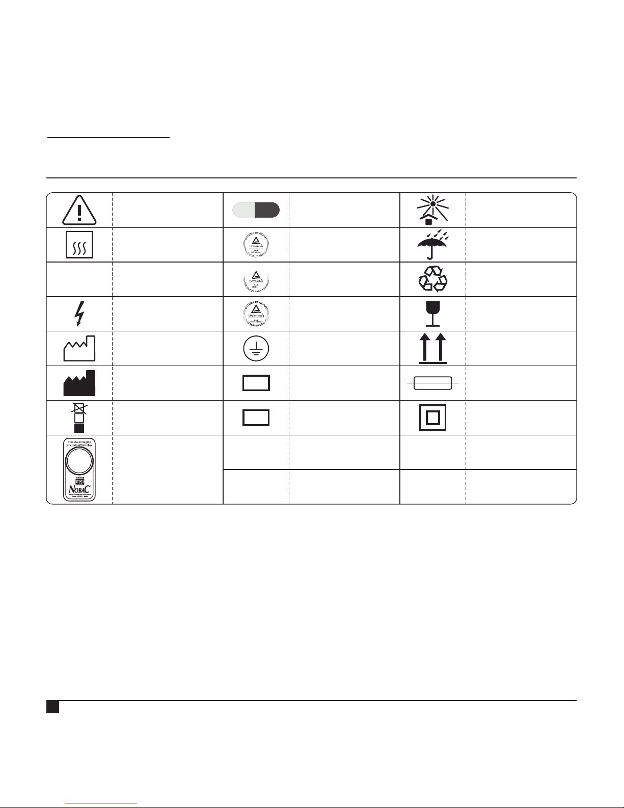
LEGEND OF SYMBOLS
CRISTÓFOLI
A U T O C L A V E S
I N S T R U C T I O N M A N U A L
Tinta
com propriedade
antimicrobiana.
~
This side up
Maximum
pile
Caution! Consult
accompanying
documents
Manufacturer
Alternate Current
Grounding
Protection Terminal
Fusible
Autoclavable
Date of
manufacture
*Boas Práticas
de Fabricação
4
P
B
F
LOT
SN
Fragile - Handle
with care
Dangerous
Electrical Tension
Serial Number
Batch code
Keep away from
sunlight
Recyclable
Keep dry
ISO 13485
ISO 14001
ISO 9001
13485
D
E
S
G
A
E
M
S
E
T
T
Ã
S
O
I
S
Class ll
Equipment
Antimicrobial
Painting
135 ºC
*BPF: Brazilian standard similar to the GMP - Good Manufacturing Practices (FDA / US)
5

6
WARNINGS!
Before sterilizing any articles, make sure you first check with their manufacturer if they are autoclavable (resistant to
the temperature of 135ºC and the presence of steam and pressure);
Do not allow patients or especially children to get close to the autoclave;
Install the autoclave in an exclusive sterilization room;
Never warm up or sterilize any kind of food in the autoclave;
Never make any kind of experiment with animals in the autoclave;
Never make any kind of use of this equipment other than the ones described in this manual.
SPECIAL MEASURES AND OBSERVATIONS DURING THE USE OF THE AUTOCLAVE:
Always make sure the door handle is properly locked before switching the autoclave on. See “How to Use the
Autoclave Vitale”, (Item c, page 13). Not following this procedure may cause the door gasket to pop off;
When unlocking the handle, the autoclave door should open easily. Always check for full depressurization, only the
first LED (position zero) of the indicative LEDs bar (Fig. 5, page 10) must be on. Never force the door to open the
autoclave!;
It is normal that some steam comes out through the door when it is opened at the end of the depressurization for
the drying stage;
Never touch the external steam exit (Fig. 1, page 8) and/or the internal surfaces of the autoclave (chamber, trays,
materials, etc.) during or right after operation, they will be very hot. Even after waiting for the materials to cool down,
it is recommended to use proper gloves to handle the sterilized materials. Improper use may cause burns,
Cristófoli is not responsible for incorrect procedures that may cause accidents;
In case of activation of one of the safety devices (sudden steam escape), generally caused by obstruction of the
steam exit internal orifice or by an obstruction of the solenoid valve, wait for the complete depressurization before
opening the door;
IMPORTANT! Always make sure you unplug the autoclave before performing any kind of maintenance like changing
the fuse or even the everyday cleaning;
We recommend reading this manual until it is fully understood. Keep it at hand and use it as a constant reference
source.
IMPORTANT SAFETY INFORMATION
Before using your autoclave Vitale, It is necessary to observe some safety measures. Autoclaves are equipment
which work at high temperature and pressure, therefore they must be handled by qualified and well-informed
personnel, regarding their features and functioning. It is essential for such qualification that the operators read all the
instructions carefully before using the autoclave to make sure to understand them correctly. The intended use of this
equipment is to perform sterilization on dental, medical and hospital instruments/articles resistant to the temperature of
135ºC, steam and pressure.
ATTENTION! TO OPEN THE AUTOCLAVE
1 - Press the door forward; 2 - Lift the handle; 3 - Slide it to the left.
CRISTÓFOLI
A U T O C L A V E S
I N S T R U C T I O N M A N U A L
INSTALLATION INSTRUCTIONS
PHYSICAL INSTALLATION
Install the autoclave on a flat, leveled and firm surface at a proper height for the operator to handle it
(approximately 80 cm / 2.6 feet from the ground) Leave enough room close to the autoclave for the proper handling ).
of the materials to be sterilized Install the autoclave in a ventilated and clean place, apart from the room where the .
patients are treated The ideal place for the installation of the autoclave should be a separate sterilization room. .
Important! .Install your autoclave where it can be easily unplugged
ELECTRICAL INSTALLATION
Check if the voltage of the autoclave is the same of the place where it will be installed. To do that, simply look at
the identification label in the back of the autoclave. See “How to Identify your Autoclave” (Fig. 24, page 18).
For the installation use a 20A grounded outlet (3 pins) connecting phase/neutral or phase/phase on the side pins
and grounding on the central pin (Fig. 2, page 8). Never connect grounding to neutral.
ATTENTION As in any other electrical device, grounding is very important for the safety of the operator and the warranty !
of your equipment. Therefore, never remove or cut the plug’s central (grounding) pin off. Non-compliance with this
requirement may damage your autoclave. Cristófoli is not responsible for damages caused by inadequate
installation, voltage and/or electricity fluctuations.
(Fig. 3, page 8).Never use extensions, voltage transformers or any kind of adapters
For the proper functioning of your autoclave, the wiring voltage must be stable, in other words, without fluctuations.
Consult a professional electrician to check the electrical wiring in your building/workplace and make sure they are in
accordance with the specifications required. It is mandatory to use an exclusive circuit breaker for the outlet
where the autoclave will be installed. If after following all the specifications, the electrical current is still fluctuating,
contact your local electricity company for repairs.
The equipment must be always carried by two people to prevent it from falling or causing an accident. The
storage/installation must be done in a place protected from the weather action (indoors) in normal temperature conditions
on a counter that can bear the weight of the autoclave.
Cristófoli Autoclave Vitale can be easily installed. Check if the wiring and voltage of your building are in accordance with
the specifications below by consulting a professional electrician or your Cristófoli local dealer. See “Warranty Terms” (Page
24) and “How to Proceed When Service is Needed” (Page 23).
In case the end user chooses an unauthorized technician to install the autoclave, such technician should follow all the
guidelines described in the instruction manual for the physical, electrical and hydraulic installation of the equipment.
Cristófoli is not responsible for any services performed in disagreement with the instruction manual that accompanies the
product.
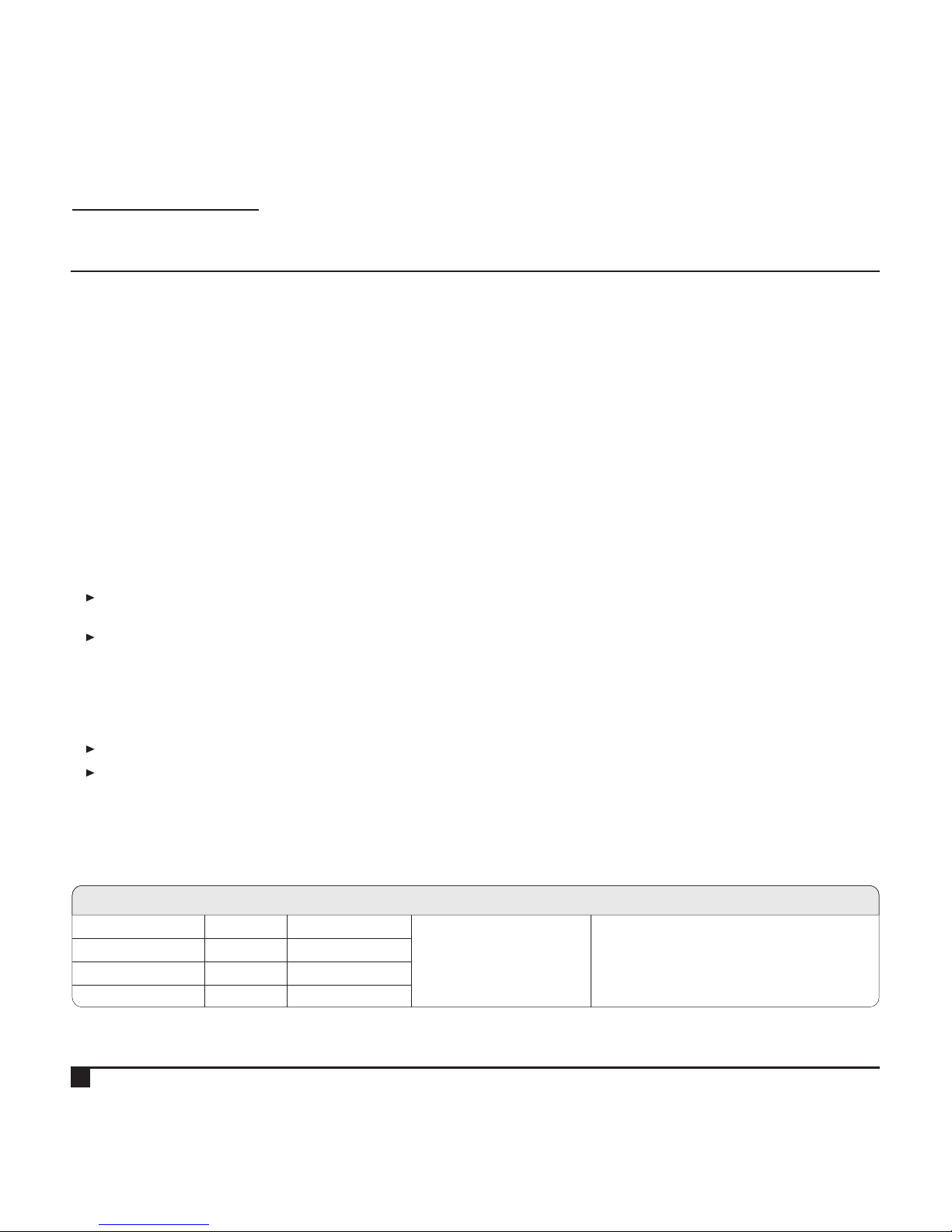
The electrical installation must follow the data from the table below.
Note: In areas where voltage is 220 V:
PP (Phase-Phase) use a “bipolar” breaker
PN (Phase-Neutral) use a “unipolar” breaker connected to phase.
1
2
4
3
7
Table 1
MODEL
NOMINAL
CURRENT
WIRING GAUGECIRCUIT BREAKER VOLTAGE
Vitale 12 - 127 V
10 A
6 A
127 V AC » 114 V - 140 V
220 V AC » 198 V - 242 V
For distance up to 5 m (16 ft) from the
circuit breaker to the outlet used to
connect the equipment, use 2,5 mm wiring.
From 5 to 15 m (16 to 46 ft) use 4 mm,
and from 15 to 50 m (46 to 164 ft) 6 mm.
1 Breaker 15 A.
1 Breaker 15 A.
Vitale 12 - 220 V
Vitale 21 - 127 V
Vitale 21 - 220 V
12 A
8 A
1 Breaker 10 A.
1 Breaker 20 A.
CRISTÓFOLI
A U T O C L A V E S
I N S T R U C T I O N M A N U A L

HYDRAULIC INSTALLATION
IMPORTANT! .For the correct connection of the components, it is essential to read the instruction manual
Purchase a heat resistant rubber hose (5/16", 300 psi as sample provided) and connect it to the external steam exit
(Fig. 1) located in the back part of the autoclave, put the clamp also provided on (Fig. 10, page 10) and fasten it with
a screwdriver The other end must be connected to the plumbing system which. must tolerate the temperature of at
least 100ºC (212ºF) or put into an open container located about 40 cm below the level of the autoclave with water
inside for steam discharge (Fig. 1A), in this case, the hose must be above the water level with a “V” cut on its end. It
also must be inspected yearly for obstructions and general condition.
Note: To replace the hose of the external steam exit, make sure the autoclave is cold and unplugged from the
electrical outlet, loosen the clamp and replace the old hose by the new one, put the clamp back on and fasten it.
WARNING! Never use a plastic hose, the heat will melt it causing an obstruction of the external steam exit and
possible damages to the equipment.
8
Fig. 2
Fig. 1A
Fig. 3
A T T E N T I O N !
GROUN DING IS
ESSEN TIAL
Table 2
X
Fig. 1
Bipolar plug and wall socket with grounding
(three pins or 2P+T) 20 A.
GR OUNDING
(D O NOT CO NNE CT GROUNDING ON NE UTR AL)
PH AS E PIN
2
NE UTRAL PIN
1
NE UTRAL PIN
127 V
CONNECTION
220 V
220 V
PHASE (127 V)NEUTRAL
NEUTRAL PHASE (220 V)
PHASE (127 V)PHASE (127 V)
PIN
2
PIN
1
EX TERNAL ST EAM
EX IT
PO WER CONNE CTO R
FU SE HOLDER
ID ENTIFIC ATI ON
LA BEL
MODELO
LOT
SN
POTÊNCIA
PRODUTO: AUTOCLAVE CRISTÓFOLI PARA ESTERILIZAÇÃO A VAPOR.
MODELO
AUTOCLAVE VITALE
FREQUÊNCIA - 50/60 Hz
REGISTRO ANVISA - 10363350005
RESPONSÁVEL TÉCNICO
EDER WILLIAM COSTA CAMACHO - CREA/PR – 87826/D
CRISTÓFOLI EQUIPAMENTOS DE BIOSSEGURANÇA LTDA
ROD BR 158 Nº 127 - CAMPO MOURÃO - PR
BRASIL - CEP 87309-650 - FONE: 55 44 3518-3432
CNPJ 01.177.248/0001-95 - INSCR. EST. 90.104.860-65
INDÚSTRIA BRASILEIRA
INSTRUÇÕES DE USO, PRECAUÇÕES, CONSERVAÇÃO E ARMAZENAMENTO:
CONSULTE O MANUAL DE INSTRUÇÕES
PRESSÃO MÁXIMA -
CAPACIDADE -
CONFORMIDADE - NORMA NBR 11817
NE VER CUT OR RE MOVE
TH E CENTRAL P IN OFF
WATER
“V ” CUT
DO N OT USE LI D
KE EP THE HOSE E ND
AB OVE THE WATER LE VEL
5 litros
1.3 gallons
PO WER CABLE
(n on-deta chabl e on mo del Vit al e 21, 127 V)
CRISTÓFOLI
A U T O C L A V E S
I N S T R U C T I O N M A N U A L

9
3
AUTOCLAVE COMPONENTS IDENTIFICATION
2
1
PANEL - It is located in the front part of the autoclave, it is injected in ABS plastic (Fig. 4, page 10).
LID - Located right behind the panel, it is responsible for closing the autoclave chamber. It’s made of stainless steel
(Fig. 7, page 10).
KEYBOARD - Located on the panel, it is where the controls keys and indicative LEDs are (Figs. 4 and 5, page 10).
PRESSURE/TEMPERATURE INDICATIVE LEDs BAR - It shows the autoclave pressure and temperature. It’s located on the
left side of the keyboard (Fig. 5, page 10).
HANDLE - Located in the front part of the autoclave (Fig. 4, page 10), it’s used to open, close and lock the
autoclave door (panel/lid set). Check the door correct locking position on Figs. 17 and 18 (Page 13).
DOOR GASKET Attached to the door, its function is to seal it with the chamber (Figs. 6 and 7, page 10), it also works -
as a safety device. See “Safety Devices” (Item 4, page 11). It requires weekly maintenance. See “Preventive
Maintenance” (Page 19).
SAFETY VALVE AND ANTI-VACCUM VALVE - The safety valve is one of the devices responsible for relieving the pressure
inside the chamber in case it goes beyond the established limits. The anti-vacuum valve has the same function, it
releases the vacuum inside the chamber when needed (Fig. 7, page 10). See “Safety Devices” (Page 11).
INTERNAL STEAM EXITS - There are two orifices inside the chamber (Fig. 11, page 11) that work as conduits for the
steam from the chamber to the solenoid valve. They must be inspected daily to be kept free from obstructions.
ATTENTION! When loading the instruments/articles into the autoclave, be careful not to put them against or too close
to the internal steam exits, that will cause interference in the cycle.
EXTERNAL STEAM EXIT - Located in the back part of the autoclave (Fig. 1, page 8), it has a diameter of 5/16” for the
connection of the discharge hose, which is then connected to the plumbing system or proper container for this
purpose. It releases the cold air in the beginning of the cycle and the steam at the end of it. See “Installation
Instructions” topic “Hydraulic Installation” (Page 8).
SOLENOID VALVE - Internal component of the equipment responsible for the deareration and depressurization. It
opens it the beginning of the heating stage eliminating the cold air from the chamber, then it shuts down to allow
pressure build up for the sterilization and opens again at the end of the cycle for the depressurization of the
chamber.
BASE - The base of the autoclave (metallic structure) is produced in carbon steel with textured electrostatic painting.
The paint used (Nobak) has antimicrobial properties (Fig. 11, page 11).
COVER - It is produced in carbon steel with textured electrostatic painting. The paint used (Nobak) has antimicrobial
properties (Fig. 11, page 11).
TRAYS HOLDER - It's provided 1 tray holder for each model, Vitale 12 (Fig. 12, page 11) and Vitale 21 with silicone
pads (Fig. 14, page 11).
TRAYS - Provided are 2 trays for Vitale 12 (Fig. 13, page 11) and 3 trays for Vitale 21 (Fig. 15, page 11), to keep the
instruments to be sterilized free from any direct contact with the water and internal surface of the autoclave chamber.
BUZZER - Internal device integrated to the circuit board, its function is to emit the beeps produced by the autoclave.
MEASURING CUP - It’s used to measure the right amount of distilled water necessary for the sterilization process (Fig. 8,
page 10).
POWER CABLE - Used to connect the equipment to the power outlet. Note: The Vitale 21 (127V) model has a non-
detachable power cable (Fig. 1, page 8 and Fig. 9, page 10).
CLAMP - Used to fasten the discharge hose to the external steam exit (Fig. 10, page 10).
4
5
CRISTÓFOLI
A U T O C L A V E S
I N S T R U C T I O N M A N U A L
6
7
9
8
10
11
12
13
14
15
16
17
18

10
CRISTÓFOLI
A U T O C L A V E S
I N S T R U C T I O N M A N U A L
CHAMBER - Produced in anodized aluminum or stainless steel, the sterilization chamber is where the instruments/articles
to be sterilized are placed (Fig. 11, page 11).
19
VITAL
FIM DE CICLO
END OF THE CYCLE
CANCELADO
CANCELLED
AQUECENDO / SECANDO
HEATING / DRYING
ESTERILIZANDO
STERILIZING
Início
Start
Cancela
Cancel
Secagem
Dry
152
148
133
130
128
127
120
111
100
°C
129
kgf/cm
2
0,5
0
1,0
1,5
1,6
1,8
2,0
3,0
4,0
1,7
Fig. 5
Drying key
Start key
Indicative LEDs Bar
(Pressure / Temperature)
Indicative LEDS
Cancel key
VITAL
FIM DE CICLO
END OF THE CYCLE
CANCELADO
CANCELLED
AQUECENDO / SECANDO
HEATING / DRYING
ESTERILIZANDO
STERILIZING
Início
Start
Cancela
Cancel
Secagem
Dry
152
148
133
130
128
127
120
111
100
°C
129
kgf/cm
2
0,5
0
1,0
1,5
1,6
1,8
2,0
3,0
4,0
1,7
Panel
Handle
Keyboard
Fig. 4
Fig. 6
Fig. 7
Anti-Vacuum Valve
Safety Valve
Door Gasket
Lid
Detail
Detail
Fig. 8
Fig. 10
Fig. 9
250 ml
50 ml
200 ml
150 ml
100 ml
Vitale 21
Vitale 12
Baby

11
CRISTÓFOLI
A U T O C L A V E S
I N S T R U C T I O N M A N U A L
Fig. 11
Base
Cover
Internal Steam Exits
Sterilization Chamber
Fig. 13
Fig. 12
Fig. 15
Fig. 14
Vitale 12
Vitale 21
Silicone pads
The autoclaves Vitale have the following safety devices:
TEMPERATURE X PRESSURE DATA CROSSING ELECTRONIC SYSTEM - Internal system of the equipment which will check
the cycle, in case any problem is detected while reading the pressure in the chamber or if it exceeds the safety
limit, the cycle will be cancelled automatically.
2
SAFETY VALVE - It opens when the pressure reaches from 2,5 to 3 Kgf/cm or 245 to 294 kPa - See “Autoclave
Components Identification” (Item 7, page 9).
ANTI-VACUUM VALVE - It works the same way of the safety valve by releasing the vacuum build-up inside the
chamber. See “Autoclave Components Identification” (Item 7, page 9).
2
DOOR GASKET - In case the pressure exceeds 3 kgf/cm or 294 kPa, the door gasket will detach from the edge of
the door making a loud noise. See “Autoclave Components Identification” (Item 6, page 9).
FUSE - Safety device which purpose is to protect the electrical wiring against peaks of energy. The fuse used is the 20
AGLF Glass - Quick Action. In case the operator wishes to replace the fuse personally, the table below will provide
the necessary information. See “Troubleshooting” (Page 21).
SAFETY DEVICES
1
2
3
4
Table 3
5
VOLTAGE
FUSE
(Vitale 12)
127 V (114 V - 140 V)
127 V
10 A (250 V)
FUSE
(Vitale 21)
12 A (250 V)
220 V
220 V (198 V - 253 V) 6 A (250 V) 8 A (250 V)
AC VOLTAGE LINE

6
THERMOSTAT - Internal safety device of the equipment. Its function is to limit the excessive heating of the chamber
during the sterilization cycles or in case a circuit board malfunction occurs.
POWER CONTROL ELECTRONIC SYSTEM Internal system of the equipment which monitors the temperature and -
pressure of the autoclave throughout the operation.
7
Warning! - During the autoclave operation, it is perfectly normal to hear some noises. The noises are generated by
the opening and closing of the valves, deaeration and depressurization, they are part of the proper functioning of the
equipment. The door gasket and the safety valve, are safety mechanisms that when activated discharge pressure
automatically producing a loud noise. This autoclave must be installed in a proper and exclusive sterilization room.
Cristófoli is not responsible for accidents that might occur due to the starts caused by the noises produced by the
autoclave.
The symbol 14 appears in some places on the autoclave. This means those items require special attention and
that the user must observe their references in the Instruction Manual provided with the equipment regarding potential
hazards offered by them and any actions to be taken should an adverse situation occur.
Cristófoli Equipamentos de Biossegurança Ltda. does not take any responsibility for failures and/or accidents
caused by the non-observance of this warning.
SAFETY NOTES
12
CRISTÓFOLI
A U T O C L A V E S
I N S T R U C T I O N M A N U A L
HOW TO USE THE AUTOCLAVE VITALE
a
Open the door of the autoclave and use the measuring cup provided to pour the correct amount of distilled water
directly into the chamber before each cycle (Fig. 16) according to the table below.
Table 4
ATTENTION! Use only distilled water. Non-compliance with this
recommendation may cause obstructions of the autoclave hydraulic
system (internal tubing and/or valves), stains on the instruments and
loss of warranty.
Fig. 16
1
/
2
l
i
t
r
o
m
l
450
400
350
300
250
200
150
100
50
Amount of distilled water for each cycle
Vitale - 21 liters
Vitale - 12 liters
250 ml / 8.5 fl.oz.
150 ml / 5 fl.oz.
Before using the autoclave for the first time, it is necessary to perform the altitude calibration procedure.
See “Altitude Calibration” (Page 16).

Close the door of the autoclave. To close it correctly, with the door open and the handle all the way to the left,
close the door by pressing it against the chamber, slide the handle to the right, and then press it all the way down
until it’s aligned with the panel (Figs. 17 and 18). To open the autoclave, follow the same procedure reversing this
sequence.
ATTENTION! Non-observance of this recommendation may jeopardize the best functioning of your autoclave, it may
even cause the door gasket to detach from the door. It is very important to have the autoclave properly closed and
locked to avoid accidents and burns.
Load the autoclave with the materials to be sterilized, be careful not to lean them against the chamber walls or
internal steam exits, that will cause interference in the cycle and damages to the articles. Do not overload the
autoclave.
b
c
13
Fig. 17
Fig. 18
VITAL
FIM DE CICLO
END OF THE CYCLE
CANCELADO
CANCELLED
AQUECENDO / SECANDO
HEATING / DRYING
ESTERILIZANDO
STERILIZING
Início
Start
Cancela
Cancel
Secagem
Dry
152
148
133
130
128
127
120
111
100
°C
129
kgf/cm
2
0,5
0
1,0
1,5
1,6
1,8
2,0
3,0
4,0
1,7
CRISTÓFOLI
A U T O C L A V E S
I N S T R U C T I O N M A N U A L
Plug the autoclave in, the Cristófoli logo will light and the autoclave will beep twice (Fig. 19). Press the START key, the
autoclave will beep once, the Heating/Drying LED will light (Fig. 20), and the autoclave will begin the heating stage
which may vary from 10 to 60 minutes depending on the temperature and altitude of the workplace as well as the
electrical wiring and quantity of material loaded. During the operation the indicative LEDs bar will show a gradual
increase/decrease of pressure and temperature. In case this is not the first cycle of the day and the temperature of
the autoclave is above 70 ºC, when pressing the START key, the autoclave will beep twice and return to Standby
mode with the Cristófoli logo lit, the Heating/Drying LED will remain off. Wait a few more minutes and try again;
d
Fig. 19 Fig. 20
VITAL
FIM DE CICLO
END OF THE CYCLE
CANCELADO
CANCELLED
AQUECENDO / SECANDO
HEATING / DRYING
ESTERILIZANDO
STERILIZING
Início
Start
Cancela
Cancel
Secagem
Dry
152
148
133
130
128
127
120
111
100
°C
129
kgf/cm
2
0,5
0
1,0
1,5
1,6
1,8
2,0
3,0
4,0
1,7
VITAL
FIM DE CICLO
END OF THE CYCLE
CANCELADO
CANCELLED
AQUECENDO / SECANDO
HEATING / DRYING
ESTERILIZANDO
STERILIZING
Início
Start
Cancela
Cancel
Secagem
Dry
152
148
133
130
128
127
120
111
100
°C
129
kgf/cm
2
0,5
0
1,0
1,5
1,6
1,8
2,0
3,0
4,0
1,7

e
As soon as the ideal temperature for the sterilization is reached, the
autoclave will begin the sterilization stage, it will beep once and the
indicative LED Sterilizing will light, remaining like that for 16 minutes
(Fig. 21).
Note 1: For altitudes above 2.000 meters, the sterilization time will be
20 minutes. In case the autoclave does not reach the ideal
pressure/temperature for the sterilization within 60 minutes, due to lack
of water, overloaded chamber or leakage, the cycle will be
automatically canceled. Fluctuations in the voltage of the power
supply may also cause the cancellation of the cycle at any time.
Note 2: In case the autoclave does not work when the START key is
pressed, see “Troubleshooting” (Page 21).
14
CRISTÓFOLI
A U T O C L A V E S
I N S T R U C T I O N M A N U A L
Fig. 21
Pressure variation range
during the sterilization stage
2
(from 1.7 to 1.8 kgf/cm / 167 to 177 kPa)
VITAL
FIM DE CICLO
END OF THE CYCLE
CANCELADO
CANCELLED
AQUECENDO / SECANDO
HEATING / DRYING
ESTERILIZANDO
STERILIZING
Início
Start
Cancela
Cancel
Secagem
Dry
152
148
133
130
128
127
120
111
100
°C
129
kgf/cm
2
0,5
0
1,0
1,5
1,6
1,8
2,0
3,0
4,0
1,7
At the end of the sterilization, the solenoid valve will open producing a characteristic click sound, the autoclave will
beep once and depressurize. When the depressurization is over, the indicative LEDs bar will show pressure “0”. Next,
the autoclave will beep 10 times and begin the drying stage, the indicative LED Heating/Drying will flash (Fig. 20,
page 13). At this moment, the operator must open the door of the autoclave and leave it ajar for the drying
cycle (Fig. 22);
Note: During the heating and drying stages, the solenoid valve makes a humming noise, similar to the one produced
by electric motors.
ATTENTION! Even after the beeps that indicate the conclusion of the cycle (the End of Cycle/Standby LED will be
flashing), the contents of the chamber will still be very hot. Never touch the internal parts of the autoclave directly
(chamber, trays, materials, etc.) when hot, wait for them to be cool enough before handling. Remember to use
safety gloves for thermal protection. Wait from 15 to 20 minutes for cooling before initiating a new cycle.
At the end of the drying stage, the autoclave will beep once and the LED End of Cycle/Standby will be flashing
continuously. In order to finalize the process and bring the system back to the standby mode, press the CANCEL key;
Turn the equipment off after use. To do that, just unplug the autoclave.
g
h
f
Upper view
Fig. 22
ATTENTION!
When opening the autoclave for drying, observe the correct
position of the door in the picture. The autoclave Vitale
dries with the door ajar, its opening is necessary to allow
steam evaporation, this will provide an efficient drying process).

The table below provides information regarding the autoclave programs.
Table 5
15
Sterilization
Temperature and Pressure
Cycles
Vitale 12/21
Heating
Time
Sterilization
Time
Drying
Time
2
Single cycle 10 to 60 min. 126 to 129 ºC / (1.7 to 1.8 kgf/cm ) 16 min. 30 min.
259 to 264 ºF / (167 to 177 kPa) *20 min.
Extra Drying - - - - - - - - - - - - - - - - - - - - - - - - - - - - 20 min.
Maximum Drying Temperature: 129 ºC / 264 ºF
*For altitudes above 2.000 meters, the sterilization time will be 20 minutes.
Note: Heating Time values are expressed taking into consideration the information in the technical data chart (Table 6, page 17) regarding
the workplace temperature and altitude.
CRISTÓFOLI
A U T O C L A V E S
I N S T R U C T I O N M A N U A L
Some situations may cause interruption and automatic cancellation of the cycle within the first 60 minutes when the
ideal pressure/temperature is not reached due to steam/pressure leak, lack of water or overloaded chamber;
When this happens, the autoclave will beep once, the Cancelled LED will light and the autoclave will depressurize
automatically. After the depressurization, press the CANCEL key to return to standby mode (the Cristófoli logo will be lit).
In case the user press the CANCEL key before the depressurization is over, the command will not have any affect.
Check the possible causes, take the necessary measures to correct the problem and perform a new cycle to
reprocess the articles according to the instructions on “How to Use the Autoclave Vitale” (Page 12). Before starting a new
cycle, the operator must check if there’s any water left in the chamber, which must be removed manually through the
door with a clean and dry cloth that does not shed. Attention! For your safety, remember to use PPE (Personal Protective
Equipment, like proper latex gloves). Wait from 15 to 20 minutes for cooling before initiating a new cycle;
If it’s necessary to interrupt/cancel the heating, sterilization or drying stage, press the CANCEL key. In this case, the
Canceled LED will remain lit and the autoclave will sound 1 continuous beep until the user press the CANCEL key
(after the depressurization) again to go back to the standby mode with the Cristófoli logo on;
ADVERSE SITUATIONS
1
2
2. 1
2. 2
2
Identification of Possible Failures during Operation - If the 4,0 kgf/cm
indicative LED starts flashing continuously, it means the autoclave has lost its
pressure calibration. See “Altitude Calibration” (Page 16).
2
During the calibration, if the 3,0 kgf/cm indicative LED starts flashing
continuously, it means that there was a calibration failure (invalid pressure). See
“Altitude Calibration” (Page 16).
Cycle Cancellation - For each type of cancellation, the autoclave will emit, depending on the reason, a different
sequence of alternate beeps, from 1 to 5, that indicate the possible cause of the cancellation as shown below:
1 beep: The user pressed the CANCEL key;
2 beeps: The relation between the temperature and the pressure of the chamber is incoherent;
3 beeps: The heating time limit was reached and there was no sterilization;
4 beeps: During the sterilization, the pressure decreased or increased beyond the acceptable limit;
5 beeps: There is pressure in the chamber when the equipment is turned on;
Fig. 23
VI TAL
FIM DE CICLO
END OF THE CYCLE
CANCELADO
CANCELLED
AQUECENDO / SECANDO
HEATING / DRYING
ESTERILIZANDO
STERILIZING
Início
Start
Cancela
Cancel
Secagem
Dry
152
148
133
130
128
127
120
111
100
°C
129
kgf/cm
2
0,5
0
1,0
1,5
1,6
1,8
2,0
3,0
4,0
1,7

Power outages or voltage fluctuations will also cause interruption and cancel the cycle automatically, in this case,
the LED End of Cycle/Standby will light, when the power returns, in case there’s pressure in the chamber, the
autoclave will depressurize, the Cancelled LED will be lit, there’s no need to press any key. Press CANCEL again to
return to the standby mode with the cristófoli logo lit. If there’s no pressure in the chamber, open the door and
remove any water left in the chamber manually with a clean and dry cloth;
At the end of the whole cycle, in case the articles are not completely dry, do not to touch the packages, that may
damage their physical integrity or jeopardize the sterilization, the operator can use the extra drying cycle as follows:
- keep the door ajar, do not remove or handle the packages, press the DRY key, the Heating/Drying LED will flash
and the 20-minute extra drying cycle will begin (Fig. 20, page 13). This cycle can be cancelled by pressing the
CANCEL key in case the operator verifies that the articles are already completely dry.
It is not normal to use the extra drying cycle regularly. In case you have to do this often, please investigate the
reason for that, it’s possible there are too many packages in the chamber or too many instruments in each
package. There must be some space between the packages to allow good steam circulation, overlapped or
incorrectly positioned packages could also interfere in the cycle, the paper side must always be facing up for better
steam evaporation. Another possibility is the inadequate opening of the door or a delay in doing it after the drying
stage beeps;
When the autoclave is in standby and detects pressure, the valve will open automatically, as soon as the pressure
falls to “0”, it will close;
After running the first cycle of the day, the autoclave must cool down from 15 to 20 minutes before initiating the next
cycle, so, if the equipment has not been cooled enough, when the START key is pressed the autoclave will beep
twice and return to Standby mode with its LED on, wait a few more minutes and try again.
3
4
16
CRISTÓFOLI
A U T O C L A V E S
I N S T R U C T I O N M A N U A L
5
6
2
3
1
4
5
6
7
ALTITUDE CALIBRATION
Unplug the autoclave;
Open the door of the autoclave, use the measuring cup to add the correct amount of distilled water directly into the
chamber before each cycle (150 ml for Vitale 12 or 250 ml for Vitale 21);
Press and hold the START and DRY keys simultaneously and plug the autoclave in;
Close the door;
The indicative LEDs on the panel will flash during the altitude measurement, the calibration will finish automatically and
the autoclave will beep continuously, indicating that the calibration was successfully performed;
Open the door, unplug the equipment and allow it to cool down;
The autoclave is ready to be used.
Note: In case the autoclave is taken to another workplace where the altitude is different, a new calibration
procedure must be performed.
In order for the autoclave to work properly, it is necessary to perform the altitude calibration procedure. Calibrate the
altitude of the autoclave as shown below, for this procedure the autoclave must be empty.

CRISTÓFOLI
A U T O C L A V E S
I N S T R U C T I O N M A N U A L
17
TECHNICAL DATA
Table 6
Note 1: In case the altitude and/or temperature of your workplace is different from the values mentioned in this manual,
contact Cristófoli by the e-mail: cac@cristofoli.com.
21 liters
Aluminum - 27,4 kg (including
components) - Stainless steel - 30 kg
(including components)
2
45,9 N/m
10 cm for each side of the autoclave
40 cm
25 x 43 cm
28,5 mm (approximately)
39,5 x 38 x 61 cm
19 x 1,2 x 38 cm (single size)
127 or 220V AC
50/60 Hz
1600 Watts
500 Watts/hour
2
216 kPa (2.2 kgf/cm )
100ºC
1.672 KJ
15ºC to 40ºC
Up to 3500 m
Capacity ................................................................
Weight ....................................................................
Weight per area of support 2 (n/m ) .........................
Overall clearance ..................................................
Clearance required for the movement of the door
Chamber internal dimension (W x D) ......................
Clearance between the trays ................................
Autoclave external dimension (W x H x D) ...............
Dimensions of the trays .........................(W x H x D)
Voltage ...................................................................
Frequency ..............................................................
Power ......................................................................
Power consumption ................................................
Maximum operation pressure .................................
Temperature of drained water ................................
Total heat in joules transmitted in one hour ............
Proper working temperature range .........................
Proper working altitude ...........................................
12 liters
Aluminum - 18,9 kg (including
components) - Stainless steel - 20,2 kg
(including components)
2
42,9 N/m
10 cm for each side of the autoclave
34 cm
22 x 30 cm
67 mm (approximately)
33,5 x 33 x 48,5 cm
15,5 x 1,2 x 28 cm (small) /
20 x 1,2 x 28 cm (large)
127 or 220V AC
50/60 Hz
1200 Watts
285 Watts/hour
2
216 kPa (2.2 kgf/cm )
100ºC
771 KJ
15ºC to 40ºC
Up to 3500 m
TECHNICAL DATA CHART Vitale 12 liters Vitale 21 liters
The Autoclaves Vitale are manufactured by Cristófoli Biossegurança, company which
Quality Management System is certified and in accordance with the ISO 9001:2008, ISO
13485:2003, BPF- Boas Práticas de Fabricação - ANVISA (Brazilian standard similar to
GMP - FDA/US) and ISO 14001:2004 - Environmental Management standards.
Certifications..........................................................
Note 2: The manufacturer reserves the right to make changes and/or improvements to this product at any moment without prior notice.

18
CRISTÓFOLI
A U T O C L A V E S
I N S T R U C T I O N M A N U A L
TIME X PRESSURE GRAPH
Graph 1
Pressure x Time
0,2
0,4
0,6
0,8
1
1,2
1,4
1,6
1,8
2
Pressure (Kgf/cm )
0
0 5 10 15 20 25
Time (Min.)
2,0
Fig. 24
HOW TO IDENTIFY YOUR AUTOCLAVE
The purpose of the label located in the back of the
equipment is to identify the autoclave technical data.
ATTENTION! - The removal of the identification label and/or
any other labels/stickers affixed to the product will cause
automatic loss of warranty.
Note: The label presented here is just a sample model for
your reference.
LOT
SN
POWER
PRODUCT: CRISTÓFOLI STEAM STERILIZATION AUTOCLAVE.
MODEL
FREQUENCY -
ANVISA REGISTER -
RESPONSIBLE TECHNICIAN -
CRISTÓFOLI EQUIPAMENTOS DE BIOSSEGURANÇA LTDA
ROD BR 158 Nº 127 - CAMPO MOURÃO - PR
BRASIL - CEP 87309-650 - FONE: 55 44 3518-3401
CNPJ 01.177.248/0001-95 - INSCR. EST. 90.104.860-65
MADE IN BRAZIL
USE INSTRUCTIONS, PRECAUTIONS, CONSERVATION AND STORAGE:
SEE INSTRUCTION MANUAL.
MAXIMUM OPERATION PRESSURE -
CAPACITY -
CONFORMITY -
MODEL
QUALITY CONTROL
Cristófoli equipment are tested and monitored individually, according to the parameters of the Table 5 (Page 15).
Besides the physical parameters, all autoclaves are tested with chemical indicators (class 5). The tests with biological
indicators are performed on a batch basis.

19
CRISTÓFOLI
A U T O C L A V E S
I N S T R U C T I O N M A N U A L
5
6
7
8
4
10
9
PREVENTIVE MAINTENANCE
Some procedures are necessary for the best functioning and durability of your autoclave, the preventive
maintenance corresponds to the fulfilment of all procedures listed below .
2
3
1
Use only distilled water;
Keep the autoclave clean. For the anodized trays/aluminum chambers or stainless steel chambers, use only a soft,
non-abrasive sponge with biodegradable neutral detergent and distilled water. To remove the foam use a cloth that
does not shed. Finish the cleaning with another cloth with alcohol 70% or peracetic acid at 1%. ATTENTION! The use of
other materials and/or products may scratch or damage these parts;
The outside cleaning of the autoclave must be done daily using a soft cloth and biodegradable neutral detergent. Next,
clean it thoroughly with a cloth with alcohol 70% or peracetic acid at 1%. The handle must be also cleaned the same way
before removing the material from the autoclave, after the sterilization;
Clean the door gasket, safety valve and anti-vacuum valve weekly with a clean cloth that does not shed, dampened in
warm water;
Replace the door gasket of your autoclave yearly and the safety and anti-vacuum valves annually ;
Replace the thermal paste of the heating element annually;
The component “lid” (Item 2, page 9) must be replaced every 10 years;
Replace the internal hoses annually;
Biological tests and preventive maintenance:
The autoclave Vitale 12/21 requires the fulfillment of some very important procedures for the sterilization:
- A biological test must be performed every 7 days. For further information about how to perform the biological
test in your autoclave, visit our site, www.cristofoli.com and go to your product support tab;
- The autoclave requires a general preventive maintenance to be performed by an authorized technician once
a year. See “How to Proceed When Service is Needed” (Page 23);
In order to avoid incrustation, the aluminum chambers of the autoclaves are anodized. Hence, it is forbidden to
use any anticrust product to perform the internal cleaning. This type of product will damage the chamber and/or
internal tubes of the autoclave.

20
CRISTÓFOLI
A U T O C L A V E S
I N S T R U C T I O N M A N U A L
PREVENTIVE MAINTENANCE TABLE
Table 7
In order to help the operator to identify the several maintenance and monitoring procedures, we have organized them
below in a table with their respective periodicity.
MAINTENANCE
DAILY
WEEKLY ANNUAL
EVERY
10 YEARS
External cleaning
Preventive cleaning (aluminum chamber)
Door gasket cleaning
Door gasket replacement
Safety and anti-vacuum valves cleaning
Replacement of the thermal paste from the heating elements
Replacement of the internal hoses
Replacement of the component “lid”
Performance of biological test
General maintenance at a technical assistance office
X
X
X
X
X
X
X
X
X
X
Safety and anti-vacuum valves replacement
X
Preventive cleaning (Stainless steel chamber)
X

21
CRISTÓFOLI
A U T O C L A V E S
I N S T R U C T I O N M A N U A L
ATTENTION! For any replacement of parts, contact your local dealer or the authorized technical assistance office. It’s
strongly not recommended the replacement of any parts by non-qualified people. We have listed below the most
frequent problems and possible solutions the operator can try in his/her own office.
TROUBLESHOOTING
If the problem persists after the verification of all the items listed, contact your local dealer.
•No power ---------------------------------------------------------------------------
•The power cable of the autoclave is not properly connected to the
autoclave or to the outlet ---------------------------------------------------------
• ---------------------------------------------------------The fuse has burned out
• ----------------------------------------------------Defective electronic circuit
• Check if there’s a power outage in your area/building;
• Connect the power cable properly;
• Replace the fuse next to the power connector. In order to replace
the fuse, unplug the equipment, remove the fuse holder cap,
replace the defective fuse, screw the fuse holder cap back into
place and turn the equipment on;
• See “How to Proceed when Service is Needed” (Page 23).
THE AUTOCLAVE DOES NOT SWITCH ON
POSSIBLE CAUSES SOLUTION
POSSIBLE CAUSES
SOLUTION
• The operator connected the autoclave to the power source but
didn’t press the Start key -------------------------------------------------------
• Press the Start key when everything is ready for the sterilization;
THE AUTOCLAVE SWITCHES ON BUT DOES NOT HEAT UP
• ----------------------------------------The heating element has burned out
• ------------------------------------------------------------Defective thermostat
• ----------------------------------------------------Defective electronic circuit
• (Page 23).See “How to Proceed when Service is Needed”
POSSIBLE CAUSES
SOLUTION
THE AUTOCLAVE SWITCHES ON, HEATS UP BUT THERE’S NO PRESSURIZATION
• Equipment installed where the altitude is above the
recommended ------------------------------------------------------------------
• In order for the autoclave to work properly, it is necessary to
perform the altitude calibration procedure. Calibrate the altitude
of the autoclave as shown on topic “Altitude Calibration” (Page
16).
• Defective temperature sensor ------------------------------------------------
• (Page 23).See “How to Proceed when Service is Needed”

22
• The wiring voltage is lower than the one needed for the
autoclave --------------------------------------------------------------------------
• valve -----Pressure/steam leak through the safety or anti-vacuum
• -----------------------Pressure/steam leak through the solenoid valve
• ---------------------------Pressure/steam leak through the door gasket
• Handle not correctly closed causing pressure/steam leak
through the lid --------------------------------------------------------------------
• ---------------------------------------------------------Overloaded chamber
• Have a professional electrician to make the necessary
modifications of your workplace wiring. See “Installation Instructions”
(Page 7);
• Turn the autoclave off and wait for it to cool down, remove the safety
and anti-vacuum valves, clean the valves and their fitting orifices and
put them back into place, replace them, if necessary;
• See “How to Proceed when Service is Needed” (Page 23).
• Perform preventive maintenance (Page 19);
• Replace the door gasket
• The handle may not be properly closed, press it down until it is flush
with the panel. See Figs. 17 and 18 (Page 13);
• Do not put more instruments than specified in each bag /package.
Use up to 75% of the chamber's capacity, that means, 5 envelopes
for Vitale 12 or 13 envelopes when using the support. The model Vitale
21 can hold 12 envelopes or 13 with the support, it can also hold 2
supports simultaneously, allowing the sterilization of 26 envelopes at a
time (envelopes 10 x 23 cm containing 6 instruments each).
Remember to leave some space between the envelopes to allow
good steam circulation and optimize drying. Never overlap
envelopes.
THE AUTOCLAVE TAKES TOO LONG TO BUILD UP PRESSURE OR DOES NOT KEEP IT, INDICATING “CYCLE CANCELLED”
If the problem persists after the verification of all the items listed, contact your local dealer.
POSSIBLE CAUSES SOLUTION
THE AUTOCLAVE PRESSURE GETS TOO HIGH, ACTIVATING THE SAFETY DEVICES
• Partial obstruction of the solenoid valve ------------------------------------
• Defective electronic circuit ----------------------------------------------------
• Obstruction of the hose connected to the external steam exit -------
• See “ (Page 23).How to Proceed when Service is Needed”
• Remove the hose connected to the external steam exit and clear
any obstruction ATTENTION! Never use a plastic hose. See .
“Installation Instructions “, topic “Hydraulic Installation” (Page 8).
POSSIBLE CAUSES SOLUTION
CRISTÓFOLI
A U T O C L A V E S
I N S T R U C T I O N M A N U A L

23
CRISTÓFOLI
A U T O C L A V E S
I N S T R U C T I O N M A N U A L
HOW TO PROCEED WHEN SERVICE IS NEEDED
First, please have in hands the model of your equipment, voltage, serial number and the date of manufacture found on
the identification label located in the back of the autoclave (Fig. 1, page 8 and Fig. 24, page 18) and a description of the
problem. Next, contact your local dealer for an evaluation and possible repair your equipment. It will be also necessary to
have the original invoice from your dealer to confirm the date of purchase.
Always contact your local dealer. If you have problems contacting your dealer, contact us by e-mail:
cac@cristofoli.com or through our website: www.cristofoli.com.
GUIDANCE FOR FINAL DISPOSAL OF THE EQUIPMENT
The environment is something that belongs to everyone, therefore, it is up to each one of us to make the decisions
that will help in its preservation and reduction of the damages resulting from human activities.
All products have a useful life span, but it is not possible to determine how long, as it varies according to the
intensity and how the equipment is used or handled. Exception made for the component “lid” which must be replaced
every 10 years in accordance to “Preventive Maintenance” (Item 7, page 19).
Cristófoli Equipamentos de Biossegurança Ltda., makes clear its concern, already demonstrated by the
implementation of the Environmental Management System, according to standard NBR ISO 14001:2004, strongly
recommends users of their products to seek the best destination when disposing your equipment or its components,
taking into account the materials recycling legislation effective in your country.
We advise you to take your equipment to specialized recycling companies that, due to the continuous and fast
paced development of new recycling technologies and materials reuse, provide the best way of disposing the
equipment. Cristófoli contributes this way to reduce the consumption of non-renewable raw materials.
.It is worth reminding you that your autoclave packaging, as indicated on the box itself, is recyclable
Other items to be observed for the preservation of our planet:
- Reduce the amount of consumption material;
- Reuse all durable goods for as long as possible;
- Properly dispose the amalgam residues because they contain mercury, which contaminates the soil;
- Recycle all possible materials at the end of their useful life span.
- Perform the correct separation of all waste.
On behalf of all users, we thank you for your comprehension and cooperation.

24
CRISTÓFOLI
A U T O C L A V E S
I N S T R U C T I O N M A N U A L
WARRANTY TERMS
CRISTÓFOLI EQUIPAMENTOS DE BIOSSEGURANÇA LTDA., warranties the Cristófoli Autoclaves for 01 (one) year against any
manufacturing defect from the date of the purchase receipt (provided it contains the serial and lot numbers of the
equipment), of which 03 (three) months refer to the legal warranty (established by section II, art. 26, CDC, Brasil) and nine (09)
months to the contractual warranty (arranged in art. 50, CDC, Brasil). Visit our website www.cristofoli.com and register your
product online.
Traveling costs (based on the distance traveled in km) and the stay of the authorized technician for installation, repair or
maintenance before or after the warranty period will be responsibility of the buyer/owner as well as the costs related to the
autoclave sterilization monitoring (tests with biological indicators) and freight charges for shipping the equipment to the
authorized technical assistance office for repairs or, if necessary, to the factory itself.
CRISTÓFOLI EQUIPAMENTOS DE BIOSSEGURANÇA LTDA., is not liable for damages / accidents caused by improper use,
operation or installation of its products, in this case the equipment will lose its warranty and the repair will be paid by the buyer
/ owner.
The warranty will be voided in cases of:
• Problems arising from natural causes (such as floods, lightning, etc.);
• Use of non-distilled water for the operation of the autoclave;
• Damage caused by accidents, such as: dents, drops, short circuits, fire, etc.;
• Damage caused by humidity, excessive exposure to sun light and salinity;
• Sinister (theft or robbery);
• Improper use / installation of the equipment and/or plugging it into an incorrect voltage outlet;
• Problems due to failure of the power supply and/or building wiring;
• Removal and/or tempering of the serial number shown in the identification label of the product;
• Signs of tampering and/or blotted out data on the purchase or service receipt of the equipment;
• Tampering and/or modification of the equipment;
• Signs of external violation of the product or broken factory seal;
• Lack of annual preventive maintenance of the equipment, which must be proved by the service receipt or neglect
regarding any item presented on the topic “Preventive Maintenance” of this instruction manual;
• Use of non-original parts or parts not acquired at the Cristófoli Authorized Service Network;
• Repairs performed by technicians who are not part of the Cristófoli Authorized Service Network;
• Noncompliance with any measure or caution recommended in the instruction manual of the product.
ATTENTION! In order to validate the contractual warranty of the product it is necessary to send a copy of the purchase
receipt to the following e-mail address: garantia@cristofoli.com.
The door gasket, safety valve, anti-vacuum valve, measuring cup and the internal hoses are not covered by the
warranty, these items are part of the preventive maintenance of the equipment (except the measuring cup), they are
continuously subjected to high pressure and temperature, therefore, they must mandatorily be replaced annually at the
owner’s expenses. They will be covered by the warranty, however, in case it is a matter of manufacturing defect.
 Loading...