

Cristec Voltage Guard-70 User Manual
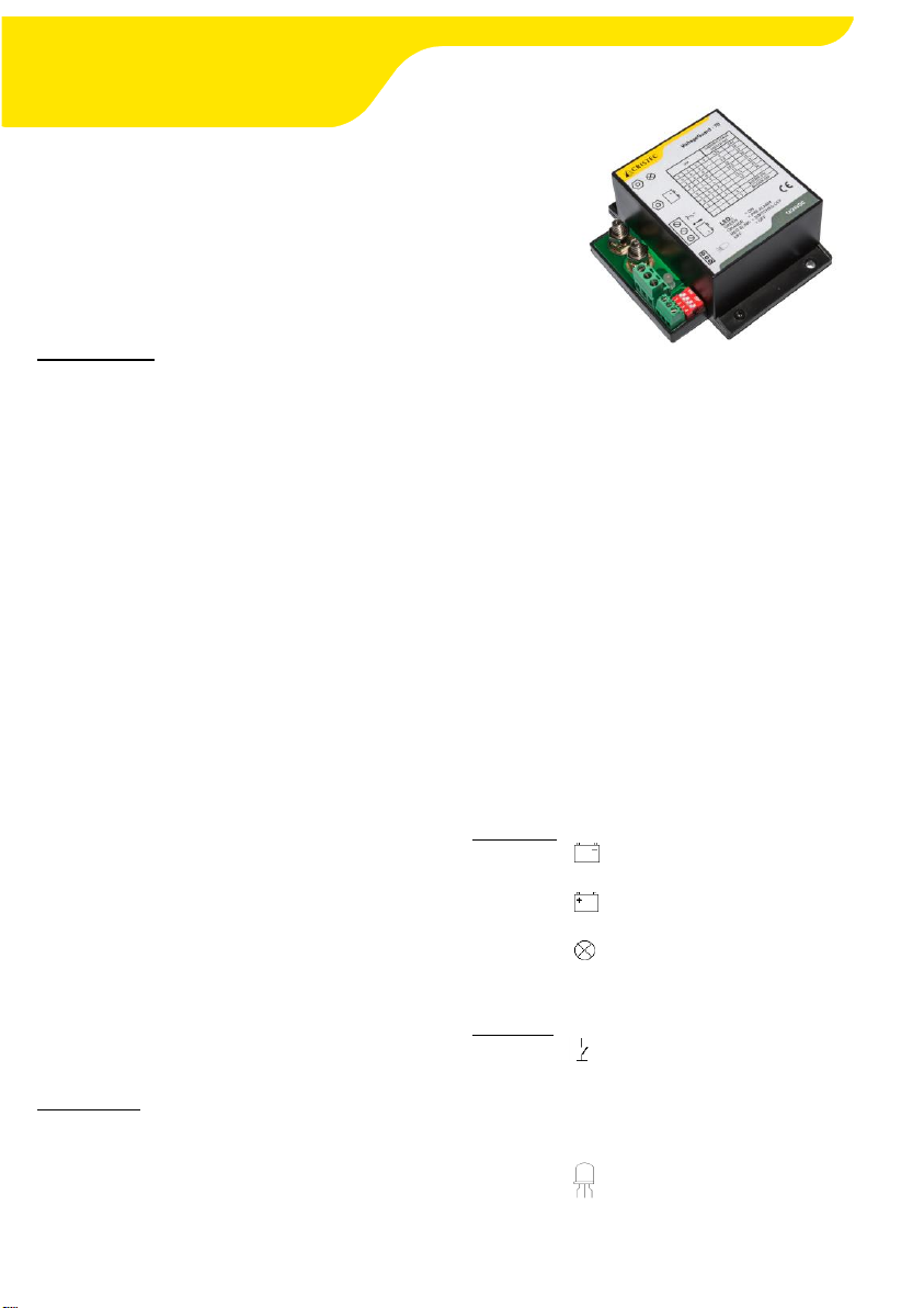
Voltage Guard – 70
www.cristec.fr
The best solution to protect your battery
against :
Deep discharge
Overvoltage
Overload
Presentation
The voltage guard protects your battery in order
to increase its duration life.
It provides a constant low voltage, overvoltage
and overload protection.
When you battery reaches the pre-set low
voltage the voltage guard will disconnect
automatically the DC consumers.
DC consumers will be switched on again
automatically when battery voltage increases and
when defined threshold is reached.
The system will operate the same say way for
over-voltage.
Low voltage threshold can be selected from
external DIP switches. The over-voltage value is
fixed.
The system can be used as manual main switch.
The output is turned off when the switch is
closed.
In this mode the voltage guard will only operate
as battery low voltage protector.
The voltage guard has an integrated buzzer and
LED to monitor its operating state.
It is compliant with all Lead battery types : wet,
sealed, gel, AGM, Calcium, etc.
Installation
The voltage guard has to be installed on a solid
surface and in a dry and well ventilated place.
Never use the voltage guard where there is any
danger of explosive gas.
Connection and possible additional protections
shall be made in compliance with local and
concerned application regulations.
Appropriate terminal shall be used to avoid bad
connection.
Fasten the bolts tightly but not over tighten
them.
Use wiring with the appropriate diameter.
Make sure the battery is fused with the right
value. This fuse can be 70A maximum, limited by
the voltage guard.
Connect the voltage guard according the wiring
diagram as shown below.
Standard :
Connect the terminal to the ground of the
installation.
Connect the terminal to the positive pole of
the battery.
Connect the terminal to the consumers +
terminal.
Optional :
Connect the terminal to a switch to ground to
use main switch function.
Connect the ! terminal to an external alarm.
This signal switches to ground in case of a low
battery (maximum alarm load 1A).
Connect the terminals to an external three
colour LED if desired.
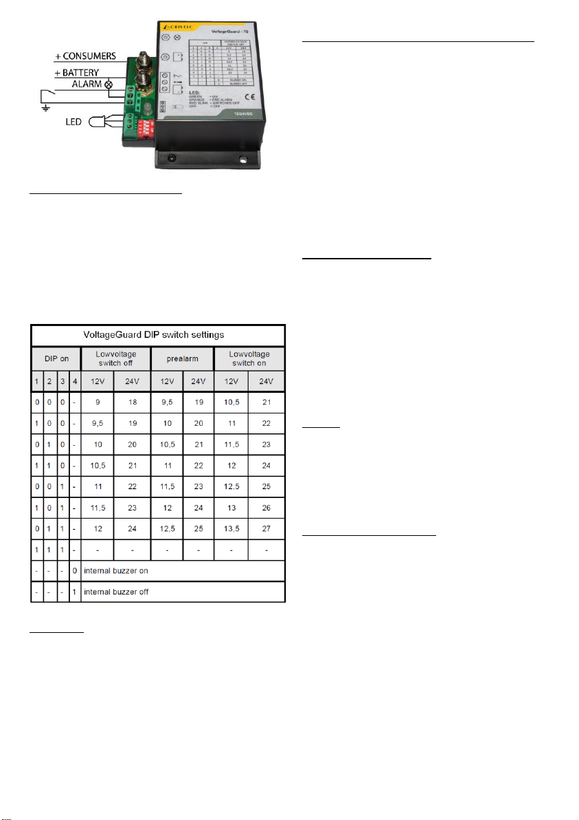
Low voltage cut-off setting
The low voltage setting can be adjusted by the
dip switches according to the table below. The
voltage guard is permanently switched on when
DIP switches 1, 2 and 3 are on. In this case the
low voltage protection is disabled. The voltage
guard works only between 8VDC and 31VDC. Use
DIP switch 4 to enable or disable the internal
buzzer.
Power up
When the power is supplied to the voltage guard
an internal self-test is done. At this moment the
voltage guard determines the nominal system
voltage. In this situation the status LED will flash
once red-green and a beep can be heard.
At a power up voltage below 16V, the voltage
guard sets itself to 12V system voltage. If the
power up voltage is higher than 16V, the voltage
guard sets itself to 24V system voltage.
Using the voltage guard as a main switch
If a panel switch is connected according to the
drawing, the main switch function can be used.
The output is turned off when the switch is
closed. The status LED is off and flashes four
times a minute. The normal voltage guard
function is activated when the switch is opened.
Normally in this case the status led is lid green
and the output is switched on. Depending on the
battery voltage the led status can be different.
Without using the switch input, the voltage guard
will just function as a low voltage protection for
your battery.
Explanation status LED
Green : the battery voltage is ok. Output is
switched on.
Green blinking : flashing four times per minute,
optional panel switch is closed and the
consumers are switched off.
Orange : the battery voltage is lower than the set
prealarm.
Red blinking : Output is switched off because of
high or low voltage or overload.
Buzzer
The internal buzzer sounds by variable intervals
before reaching the shut off point. The interval
between the sounds will be shorter with every
repetition. Pauses between alarm pulses: 600s 300 s - 150s - 75s - 38s - 19s - 9s.
Technical specifications
Rated current (constant) : 70 A
Max current (10s @ 20C°) : 140 A
Voltage : 12 and 24 VDC
Input voltage range : 8 - 31 VDC
Consumption : > 2mA (LED Off)
Presentation : Plastic housing with external
fixings – IP51
Connection : on threaded roads
Dimensions (l x h x e) : 100 x 89.2 x 43 mm
Weight : 0.21 Kg
Operating temperature : from -10°C to +60°C
Storage temperature : from -20°C to +85°C
12V low voltage adjustment : 9 - 12 VDC
12V overvoltage threshold : 15.5 VDC
24V Low voltage adjustment : 18 - 24 VDC
24V overvoltage threshold : 31 VDC
 Loading...