

Page 1

FICHA TECNICA DE:
RADIO APRISA 4RF
Page 2
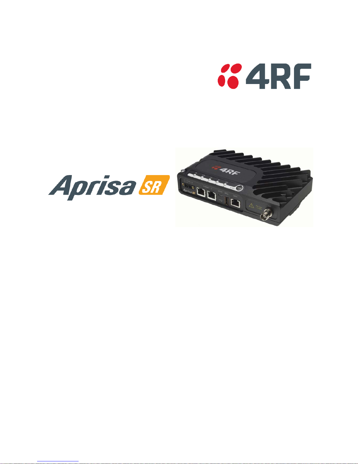
Product Description
Page 3

2 |
Aprisa SR Product Description
Compliance General
The Aprisa SR digital radio predominantly operates within frequency bands that require a site license be
issued by the radio regulatory authority with jurisdiction over the territory in which the equipment is
being operated.
It is the responsibility of the user, before operating the equipment, to ensure that where required the
appropriate license has been granted and all conditions attendant to that license have been met.
Changes or modifications not approved by the party responsible for compliance could void the user’s
authority to operate the equipmen t.
Equipment authorizations sought by 4RF Communications are based on the Aprisa SR radio equipment
being installed at a fixed location and operated in point-to-multipoint mode within the environmental
profile defined by EN 300 019, Class 3.4. Operation outside these criteria may invalidate the
authorizations and / or license conditions.
The term “Radio” with reference to the Aprisa SR User Manual, is a generic term for one end station of a
point-to-multipoint Aprisa SR network and does not confer any rights to connect to any public network or
to operate the equipment within any territory.
Compliance ETSI
The Aprisa SR radio is designed to comply with the European Telecommunications Standards Institute
(ETSI) spec if ica tions as follows:
Radio perform ance EN 300 113-2
EMC EN 301 489 Parts 1 & 5
Environmental EN 300 019, Class 3.4
Safety EN 60950-1:2006
Frequenc y ban d Channel size Power input Notified
body
136-174 MHz 12.5 kHz 12 VDC
400-470 MHz 12.5 kHz 12 VDC
Page 4
| 3
Aprisa SR Product Description
RF Exposure Warning
WARNING:
The installer and / or user of Aprisa SR radios shall ensure that a separation distance
as given in the following table is maintained between the main axis of the terminal’s
antenna and the body of the user or nearby persons.
Minimum separation distances given are based on the maximum values of the
following meth odologi es :
1. Maximum Permissible Exposure non-occupational limit (B or gene ral public) of
47 CFR 1.1310 and the methodology of FCC’s OST/OET Bulletin number 65.
2. Reference levels as given in Annex III, European Directive on the limitation of
exposure of the general public to electromagnetic fields (0 Hz to 300 GHz)
(1999/519/EC). These distances will ensure indirect compliance with the
requirements of EN 50385:2002.
Frequenc y (MHz) Maximu m Power
(dBm)
Maximum Antenna
Gain (dBi)
Minimum Separa tion
Distance
(m)
136 + 37 15 2.5
174 + 37 15 2.5
330 + 37 15 2.5
400 + 37 15 2.5
470 + 37 15 2.3
520 + 37 15 2.2
850 + 37 28 7.7
960 + 37 28 7.2
Page 5

Contents | 5
Aprisa SR Product Description
Contents
1. Introduction ................................................................................ 7
The 4RF Aprisa SR Radio ......................................................................... 7
Product Overview ................................................................................ 8
Network Coverage and Capacity ........................................................ 8
Remote Messaging ......................................................................... 8
Repeater Messaging ....................................................................... 9
Product Features ................................................................................ 10
Functions .................................................................................. 10
Performance .............................................................................. 10
Usability ................................................................................... 10
Architecture...................................................................................... 11
Security ........................................................................................... 12
Interfaces ......................................................................................... 13
Antenna Interface ........................................................................ 13
Ethernet Interface ....................................................................... 13
USB Interfaces ............................................................................ 13
RS-232 Interface .......................................................................... 13
Product Options ................................................................................. 14
Dual Antenna .............................................................................. 14
Mounting .......................................................................................... 15
DIN Rail Mounting ........................................................................ 15
Rack Shelf Mounting ..................................................................... 16
Wall Mounting ............................................................................. 17
2. Specifications ............................................................................ 18
RF Specifications ................................................................................ 18
ETSI Compliant ............................................................................ 18
Frequency Bands .................................................................. 18
Channel Sizes ...................................................................... 18
Product Range ..................................................................... 18
Transmitter ......................................................................... 19
Receiver ............................................................................ 19
Modem .............................................................................. 20
Data Payload Security ............................................................ 20
Interface Specifications ........................................................................ 21
Ethernet Interface ....................................................................... 21
RS-232 Asynchronous Interface ......................................................... 21
Power Specifications ............................................................................ 22
Power Supply .............................................................................. 22
Power Consum pt ion ...................................................................... 22
Power Dissipation ........................................................................ 22
General Specifications .......................................................................... 23
Environmental ............................................................................ 23
Mechanical ................................................................................ 23
ETSI compliance .......................................................................... 23
Page 6

6 | Contents
Aprisa SR Product Description
3. Management ............................................................................. 25
SuperVisor ........................................................................................ 25
Viewing the Aprisa SR Terminal Settings .............................................. 25
Configuring the Aprisa SR Terminal Details ........................................... 26
Configuring the Aprisa SR RF Netwo rk Details ....................................... 26
Configuring the Aprisa SR Radio Settings ............................................. 27
Command Line Interface ....................................................................... 28
Management Display Panel ..................................................................... 29
LED Display Pa ne l ............................................................................... 30
Normal Operation ........................................................................ 30
Software Upgrade ........................................................................ 30
Test Mode ................................................................................. 31
4. Applications .............................................................................. 32
Basic point-to-multipoint application ........................................................ 32
Advanced point-to-multipoint application with repeater ................................. 33
Multi-interface point-to-multipoint application ............................................ 34
5. Architecture ............................................................................. 35
Product Description ............................................................................. 35
Frame ...................................................................................... 35
MAC Header ........................................................................ 35
Network Header ................................................................... 36
Payload .................................................................................... 36
Auxillary Frame ........................................................................... 36
Physical Layer ............................................................................. 37
Data Link Layer / MAC layer ............................................................ 37
Channel Access .................................................................... 37
Hop by Hop Transm i ssi on ......................................................... 37
Network Layer ............................................................................ 38
Packet Routing ..................................................................... 38
Product Operation............................................................................... 39
Carrier Sense Disabled ................................................................... 39
Carrier Sense Enabled ................................................................... 40
Product Architecture ........................................................................... 43
Radio Block Diagram ..................................................................... 44
Modem Block Diagram ................................................................... 44
6. Contact Us ................................................................................ 45
Page 7
Introduction | 7
Aprisa SR Product Description
1. Introduction
The 4RF Aprisa SR Radio
The 4RF Aprisa SR is a point-to-multipoint digital radio providing secure narrowband wireless data
connectivity fo r SCADA, infrastructure and telemetry applications.
The radios carry a combination of serial packet data and Ethernet data between the Base Station,
Repeater Stations and Remote Stations.
The Aprisa SR is configurable as a point-to-multipoint Base Station, a Remote Station or a Repeater
Station.
Page 8

8 | Introduction
Aprisa SR Product Description
Product Overview
Network Coverage and Capacity
In a simple po i nt -to-multipoint network, an Aprisa SR, configured as a base station, will communicate with
multiple remote units in a given coverage area. With a link range of up to 60 km a typical deployment will
have 30 – 50 remote stations attached to the base station. However, geographic features, such as hills,
mountains, trees and foliage, or other path obstructions, such as buildings, tend to limit radio coverage.
Additionally, geography may reduce network capacity at the edge of the network where errors may occur
and require retransmission. However, the Aprisa SR uses Forward Error Correction (FEC) which greatly
improves the sensitivity performance of the radio resulting in less retries and minimal reduction in
capacity.
Ultimately , the overall perfo rmance of any spec i fi c network will be defin ed by a range of factors including
the geographic location, the number of remote stations in the base station coverage area and the traffic
profile across the network. ). Effective network design will distribute the total number of remote stations
acr oss the available base stations to ensure optimal geographic coverage and network capacity.
R emote M essa ging
Base stations are fitted with omni-directional antennas and the remote stations use directional Yagi
antennas for higher gain. On start-up the base stat ion transmits a registration message which is recognised
by the remote stations which respond with their own registration message. This allows the base station to
record the details of all the remote stations active in the network.
There are two message types in the Aprisa SR network, broadcast messages and unicast messages.
Broadcast messages are transmitted by the base station to the remote statio ns and unicast messages are
transmitted by the remote station to the base station.
All the remote stations, within the coverage area, will receive the messages broadcast from the base
station, but only the radio the message is intended for will action the message. Only the base station can
receive the unicast messages transmitted from the remote station. Unicast messages are ignored by other
remote stations which may be able to receive them. The Aprisa SR network is not designed for remote
stations to communicate with other remote stations.
Page 9

Introduction | 9
Aprisa SR Product Description
R epeat er Mess agin g
The Aprisa SR uses a routed protocol throughout the network whereby messages contain source and
destination addresses. Upon registration, the radios populate an internal neighbor table to identify the
radios in the network. The remote stations will register with a base station, or a repeater, and the
repeater registers with a base station. In networks with a repeater, the repeater must register with the
base station before the remotes can register with the repeater.
Additionally, all messages contain a ‘message type’ field in the header and messages are designated as
either a ‘broadcast’ message, originating from a base station, or a ‘unicast’ message, originating from a
remote station.
In a network with a repeater, or multiple repeaters, the base station broadcasts a message which contains
a message type, a source address and a destination address. The repeater receives the message and
recognizes it is a broadcast message, from the message type and source address and re-broadcasts the
message across the network. All remote stations in the coverage area will receive the message but only
the radio with the destination address will act upon the message.
Similarly, the remote station will send a unicast message which contains a message type (unicast) a source
address and a de stination address (the base station). The repeater will receive this message; recognize
the message type and source address and forward it to the destination address.
It is this methodology which prevents repeater-repeater loops. If there is repeater (A) which, in some
circumstances, is able to pick up the RF signal from another repeater (B), it will not forward the message
as it will only forward broadc ast messages from the base station (reco gnised by the sourc e address). For
unicast messages the repeater (A) will recognize that the message (from repeater (B)) is not from a
remote with which it has an association and similarly ignore the message.
Page 10

10 | Introduction
Aprisa SR Product Description
Product Features
Functions
• Point-to-Point (PTP) or Point-to-Multipoint (PMP) operation half duplex
• Licensed frequency bands:
VHF 136-174 MHz
UHF 330-400 MHz
†
UHF 400-470 MHz
UHF 450-520 MHz
†
UHF 850-960 MHz
†
• Channel sizes:
6.25 kHz
†
12.5 kHz
25 kHz
†
• Typical deployment of 30 Remote Stations from one Base Station with a practical limit of a few
hundred Remote Stations.
• Dual antenna option for external duplexers or filters (half duplex operation)
• Ethernet data interface plus RS-232 asynchronous data i nter face.
• Data encryption and authentication.
• Complies with international standards, including ETSI RF, EMC, safety and environmental
standards.
†
Future Product Release
Performance
• Long distance operation (typically 30 km radius).
• High transmit power.
• Low noise receiver.
• Forward Error Correction.
• Electronic tuning over the frequency band.
• Thermal management for high power over a wide temperature range.
Usability
• Configuration / diag nosti cs via fro nt panel Management Port USB interface, Ethernet interface.
• Remote station configuration / diagnostics over the radio link.
• LED display for on-site diagnost ics.
• Optional management display for advanced on-site configuration.
• Firmware upgrade and diagnostic reporting via the Host Port USB flash drive .
• Simple installation with integrated mounting holes for wall, DIN rail and rack shelf mounting.
Page 11

Introduction | 11
Aprisa SR Product Description
Architecture
The Aprisa SR Architecture is based around a layered TCP/IP protocol sta ck:
• Physical
Proprietary wire le s s
Standard RS-232 and Ethernet
• Link
Proprietary wireless (channel access, ARQ, segmentation)
Standard Eth ernet
• Network
Standard IP
Proprietary automatic radio routing table population algorithm
• Transport
Standard TCP, UD P
• Application
Proprietary management application software
Page 12

12 | Introduction
Aprisa SR Product Description
Security
The Aprisa SR provides security features to implement the key recommendations for industrial control
systems. The security provide d builds upon the best in class from multiple standards bodies, including:
• IEC/TR 62443 (TC65) “Industrial Communications Networks – Network and System Security”.
• IEC/TS 62351 (TC57) “Power System Control and Associated Communications – Data and
Communicat ion Se curity” .
It also adds addit io n al security features through Layer 3 network integration.
The security features implemented are:
• Licensed radio spectrum protects against interference.
• Proprietary physical layer protocol and modified MAC layer protocol based on standardized IEEE
802.15.4.
• Data payload security:
CCM Counter with CBC-MAC integrity (NIST special publication 800-38C).
• Data encryption:
Counter M od e Encryption (CTR) using Advanced Encryption Standard (AES ).
• Data authentication:
Cipher Block Chaining Message Authentication Code (CBC-MAC) using Advanced Encryption
Standard (AE S).
• Secured management interface protects configuration.
• Address filtering enables traffic source authorization
†.
• Distributed Layer 3 firewall protects remote nodes
†.
• Segregated traffic flow enables node isolation, with VLAN and Layer 3 subnets
†.
†
Future Product Release
Page 13

Introduction | 13
Aprisa SR Product Description
Interfaces
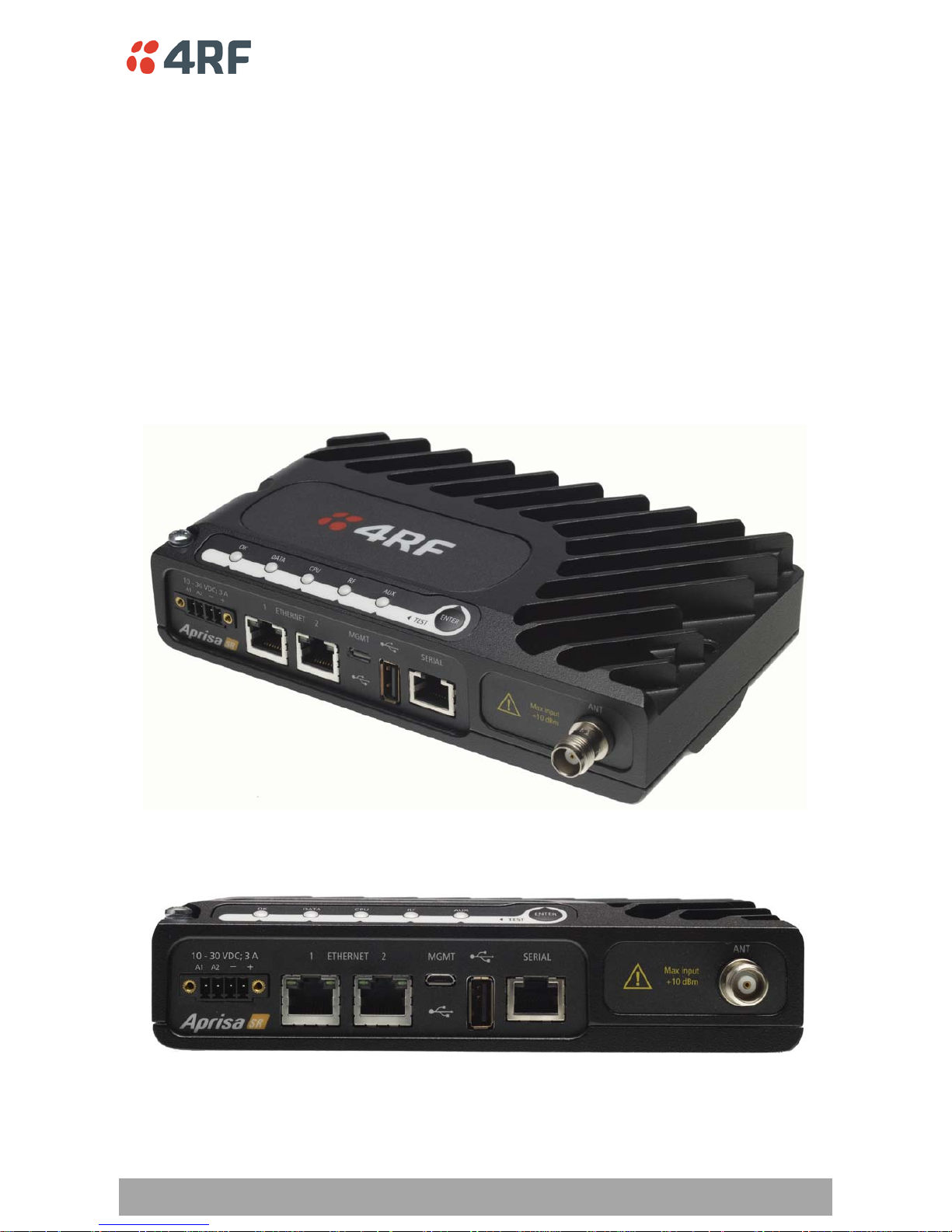
Antenna Interface
• 1 x TNC, 50 ohm, female connector
Single Antenna Option
• 2 x TNC, 50 ohm, female connectors
Dual Antenna Option
Ethernet Interface
• 2 x ports 10/100 base-T Ethernet layer 2 switch using RJ-45.
Used for Ethernet user traffic and product management.
USB Interfaces
• 1 x Management Port using USB micro type B connector.
Used for product configuration with the Command Line Interface (CLI).
• 1 x Host Port using U S B standard type A connector.
Used for softwa re upg ra de and diagnostic reporting.
RS-232 Interface
• 1x RS-232 asynchronous port using RJ-45 connector.
Used for RS -232 async user traffic only.
Page 14
14 | Introduction
Aprisa SR Product Description
Product Options
Dual Antenna
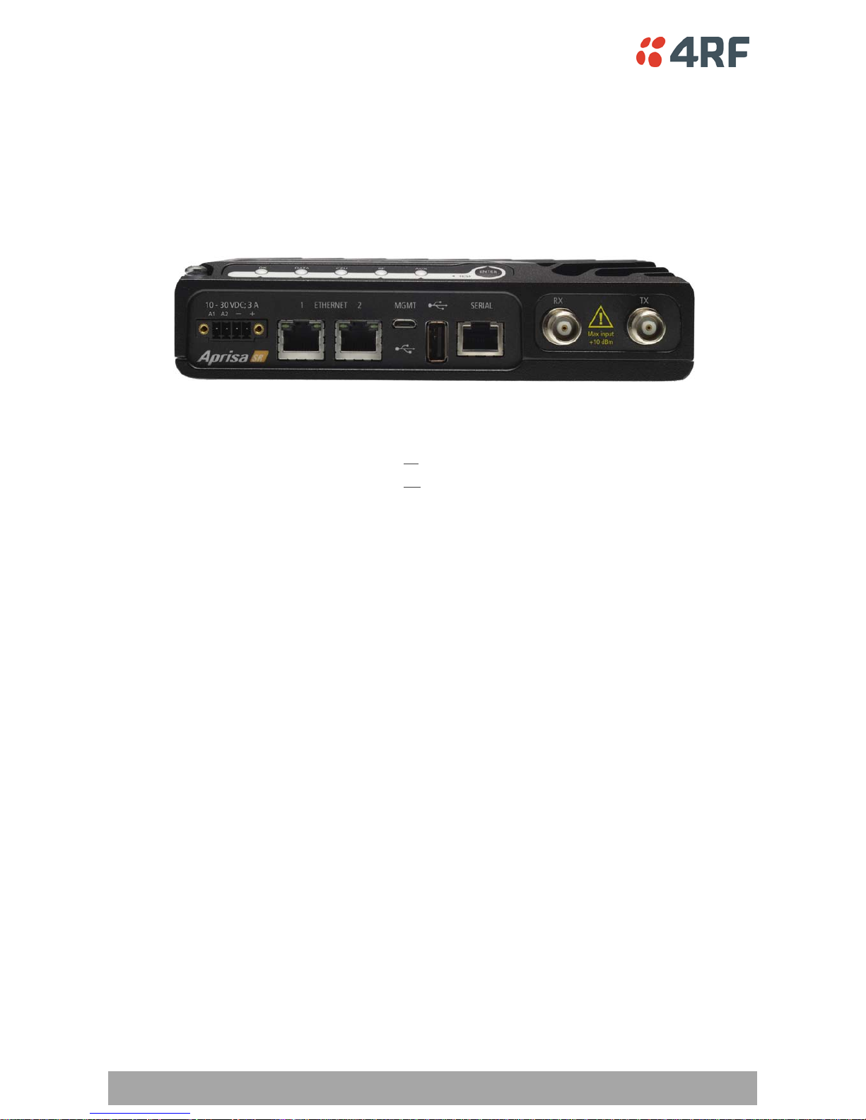
The standard Aprisa SR uses a one o r two frequency ½ duplex transmission mode which eliminates the
need for a duplexer. However, a Dual Antenna option is available for separate transmit and receive
antenna connection to support external duplexers or filters. The transmissi on remain s half duplex.
Antenna Option Par t Num b e r
Single Antenna APSR-N400-012-
SO
Dual Antenna
-12-ETAA
APSR-N400-012-DO -12-ETAA
Page 15
Introduction | 15
Aprisa SR Product Description
Mounting
The Aprisa SR has four threaded holes (M4) in the enclosure base and two holes (5.2 mm) through the
enclosure for mounting.
Mounting options include:
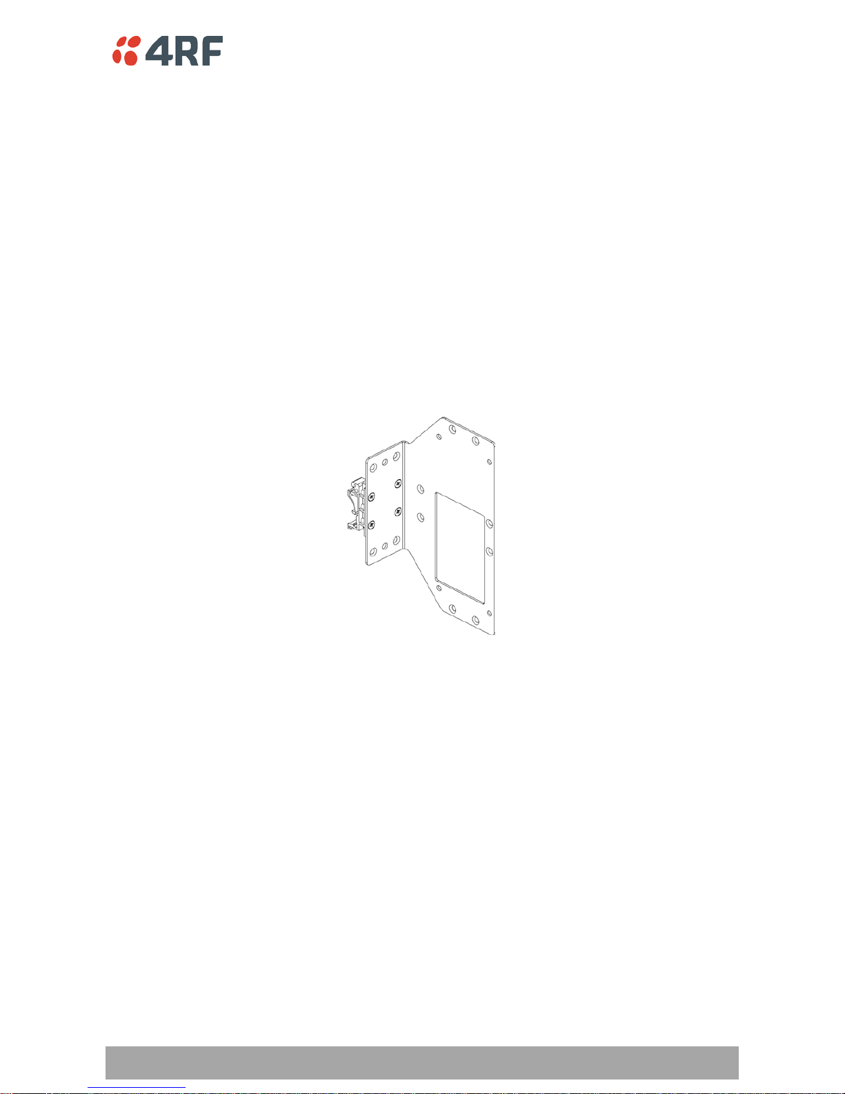
• DIN rail mounting with the Aprisa SR DIN Rail Mounting Bracket
• Rack shelf mounting
• Wall mounting
• Outdoor enclosure mounti ng
DIN Rail Mounting
The Aprisa SR has an optional accessory part ‘4RF Aprisa SR Acc, Mounting, Bracket, DIN Rail’.
Page 16
16 | Introduction
Aprisa SR Product Description
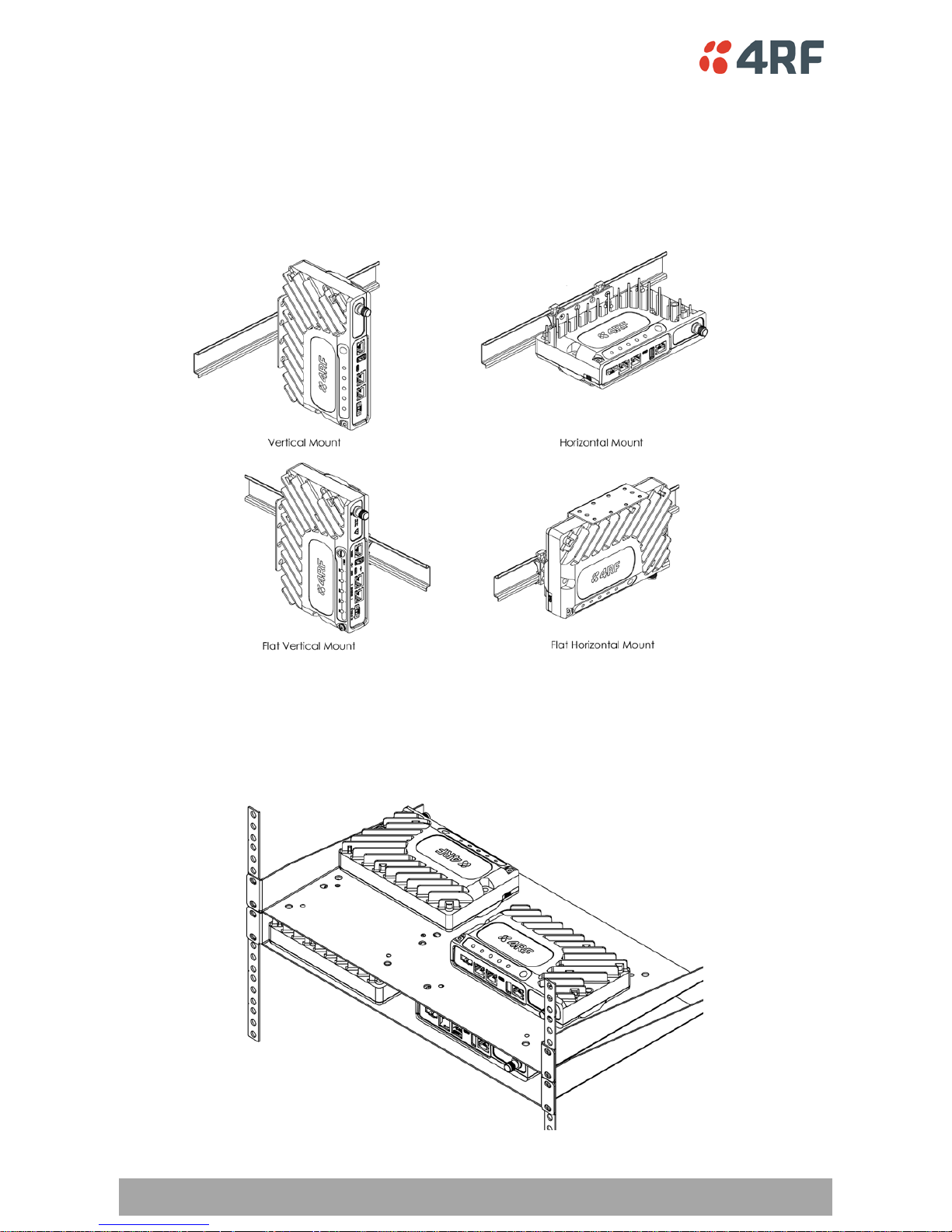
The Aprisa SR DIN rail mounting bracket can be mounted in four positions on a horizontal DIN rail:
• Vertical Mou nt (ve rtical enclosure pe rpendicular to the mount )
• Horizontal Mount (horizontal enclosure perpendicular to the mo unt).
• Flat Vertical Mo unt (vertical enclosure parallel to the mount)
• Flat Horizont a l Mo unt (h orizontal enclo sure pa ra llel to the mount)
Rack Shelf Mounting
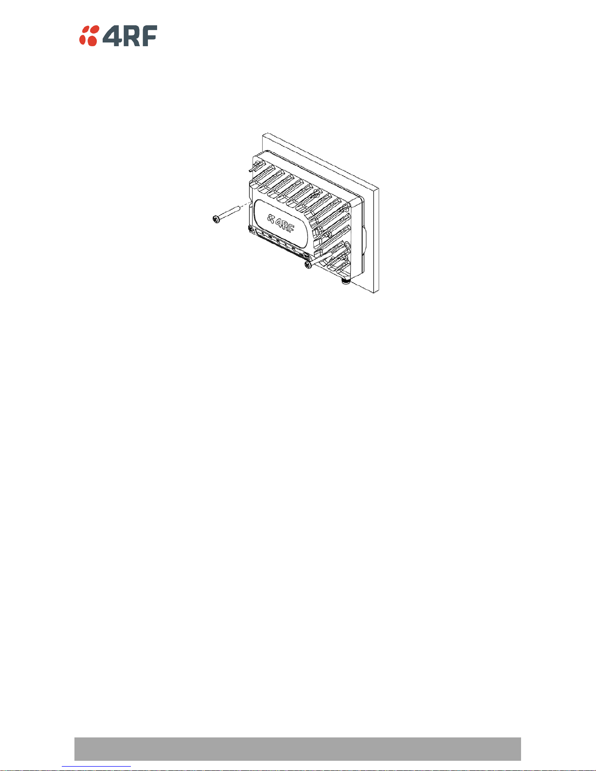
The Aprisa SR can be mounted on a rack mount shelf using the four M4 threaded holes in the Aprisa SR
enclosure base. The following picture shows Aprisa SR mounted on 1 RU rack mounted shelves.
Page 17
Introduction | 17
Aprisa SR Product Description
W all Moun ting
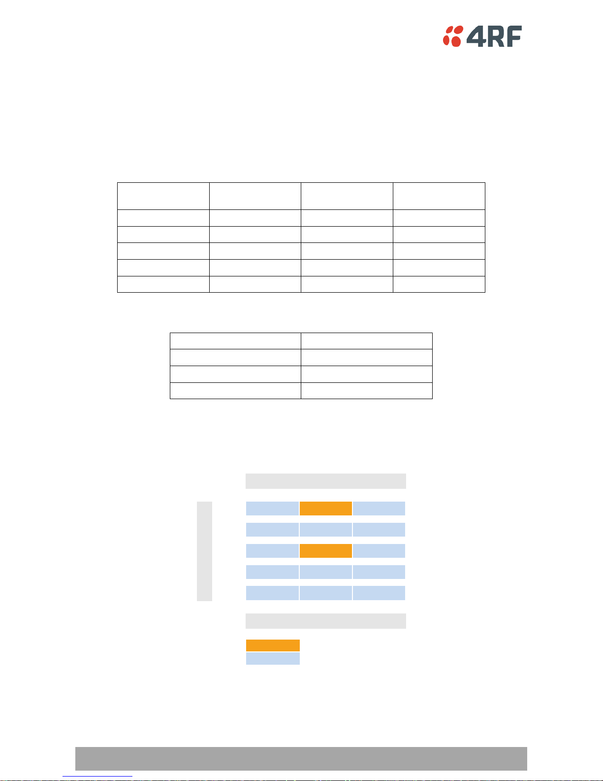
The Aprisa SR can be mounted on a wall using the two holes through the enclosure (5.2 mm diameter).
Typically, M 5 sc rews longer than 35 mm would be used.
Page 18
18 | Specifications
Aprisa SR Product Description
2. Specifications
RF Specif ications
ETSI Compliant
Frequency Bands
Broadcast Band Freque ncy Band Frequency Tuning
Range
Synthesizer Step
Size
VHF 136 MHz 136-174 MHz 3.125 kHz
UHF 330 MHz † 330-400 MHz 6.250 kHz
UHF 400 MHz 400-470 MHz 6.250 kHz
UHF 450 MHz † 450-520 MHz 6.250 kHz
UHF 900 MHz † 850-960 MHz 6.250 kHz
Channel Sizes
Channel Size Gross Radio Capacity
6.25 kHz † 4.8 kbit/s
12.5 kHz 9.6 kbit/s
25 kHz † 19.2 kbit/s
†
Future Product Release
Product Range
6.25 12.5 25
136
330
400
450
900
4.8 9.6 19.2
Current P r oduc t Release
Fut ur e P r oduc t Release
Frequenc y B and ( M Hz )
Gross Radio capacity (kbit/s)
Channel Size (kHz)
Page 19

Specifications | 19
Aprisa SR Product Description
Transmitter
Power ou tp ut 0.1 to 5.0 W (+20 to +37 dBm, in 1 dB steps)
Adjacent channel power < - 60 dB C
Transient adjacent channel power < - 50 dB C
Spurious emissions < - 37 dB m
Attack time < 1.5 ms
Release time < 1.5 ms
Data turnaround time < 10 ms
Frequency stability ± 1 ppm
Frequency aging < 1 ppm / annum
Synthesizer lock time < 1.5 ms (5 MHz step)
Receiver
6.25 kHz † 12.5 kHz 25 kHz †
Receiver Sensitivity BER < 10-2 –119 dBm –117 dBm –114 dBm
BER < 10-3 –114 dBm
BER < 10-6 –110 dBm
Adjacent Selectivity > 60 dB > 60 dB > 70 dB
Co-channel rejectio n > –12 dB
Intermodulation response
rejection
> 70 dB
Blocking or desensitization > 84 dB
Spurious response rejection > 75 dB
Page 20
20 | Specifications
Aprisa SR Product Description
Modem
Modulation 4-CPFSK
Forward Error Correc tion ¾ Trellis code
Data Payload Security
Data payload security CCM* Counter with CBC-MAC
Data encryption Counter Mod e Encryption (CTR) using Advanced
Encryption Sta n da rd (AES) 128, 192 or 256
Data authentication Cipher Block Chaining Message Authentication
Code (CBC-MAC) using Advanced Encryption
Standard (AES) 128, 192 or 2 56
†
Future Product Release
Page 21
Specifications | 21
Aprisa SR Product Description
Interf ace Specifications
Ethernet Interface
The Ap risa SR radio features an integrated 10Base-T/100Base-TX layer-2 Ethernet switch.
To simplify network s etup, each port suppo rts auto-negotiation and auto-sensing MDI/MDIX. Operators can
select from the following preset modes:
• Auto neg o tiate
• 10Base-T half or full duplex
• 100Base-TX half or full duplex
The switch is I EEE 8 02.3-compa tible. It passes VLAN ta g ged traffic.
General Interface RJ-45 x 2 (Integrated 2-port switch)
Cabling CAT-5 UTP, supp orts auto MDIX (Sta ndard Ethernet)
Maximum line length 100 metres o n c a t-5 or better
Bandwidth allocation
The Ethernet capacit y maximu m is d etermined by the
available radio link capacity.
Maximum transmission unit Option setting o f 1522 or 1536 octets
Address table size 1024 MAC addresses
Ethernet mode
10Base-T or 100 Base-TX
Full dupl ex o r hal f duplex
(Auto-negotiating and auto-sensing)
Diagnostics Left Green LED
Off: no Ethernet signal received
On: Ethernet signal received
Right Green LED
Off: Indicates no data traffic present on the interface
Flashing: Indicates data traffic present o n t he interface
RS-232 Asynchronous Interface
The Aprisa SR radio’s ITU-T V.24 compliant RS-232 interface is configured as a Cisco® pinout DCE. The
interface terminates to a DTE using a straight-through cable or to a DCE with a crossover cable (null
modem).
The interface uses two handshaking control lines between the DTE and the DCE.
General Interface ITU-T V.24 / EIA/T IA RS-232E
Interface directi o n DCE only
Maximum line length 10 metres
Async
parameters
Standard mode data bits 7 or 8 bits
Standard mode parity Configu ra bl e f or None, Even or Odd
Standard mode stop bits 1 or 2 bits
Interface baud rates
300, 1200, 240 0, 4800, 9600, 19200, 38400, 57600 and
115200 bit/s
Control signals DCE to DTE CTS, RTS, DSR, DTR
Page 22
22 | Specifications
Aprisa SR Product Description
Power Specifications
Power Supply
Nominal voltage +13.8 VDC (negative earth)
Input voltage range +10 to +30 VDC
Maximum pow er input 30 W
Connector
Phoenix Contact 4 pin male screw fitting
MC 1.5/ 4-GF-3.5
Power Consumption
Mode Power Consu m p t ion
Transmit / Receive < 22.5 W for 5W transmit power
< 15.0 W for 1W transmit power
Receive only < 6 W full Ethernet traffic activity
< 4.5 W no Ethernet traffic activity
Power Dissipation
Transmit Power
Power
Dissipation
1W transmit power < 14.0 W
5W transmit power < 17.5 W
Page 23

Specifications | 23
Aprisa SR Product Description
General S p ecifications
Environmental
Operating tempera ture range -40 to +70˚ C
Storage temperature ra ng e -40 to +80˚ C
Operating humidity Maximum 95% non-condensing
Acoustic noise emission No audible noise emission
Mechanical
Dimensions Width 177 mm
Depth 110 mm (126 mm with TNC connector)
Height 41.5 mm
Weight 720 g
Colour Matt black
Mounting
Wall (2 x M5 screws)
Rack shelf (2 x M4 screws)
DIN rail bracket
ETSI compliance
Radio EN 300 113
EMI / EMC EN 301 489 Parts 1 & 5
Safety EN 60950
Environmental ETS 300 019 Class 3.4
Page 24
Management | 25
Aprisa SR Product Description
3. Management
SuperVisor
The Aprisa SR c ontains an embedde d web serv er applicatio n (SuperVisor) to enable element management
with any major web browser (such as Mozilla Firefox, Microsoft® Inte rnet Explorer).
SuperVisor enables o perators to configure and manag e the Aprisa SR base station radio and repeater /
remote station radios over the radio link.
The key features of SuperVisor are:
• View and set standard radio configuration parameters, including frequencies, transmit power,
channel access, serial, Ethernet and USB port settings
• Set terminal operating mode, whether base station, remote station or repeater station
• Set and view security parameters, including keys
• Display performance and alarm information, including RSSI, alarm status, time-stamped events,
alarm parameters
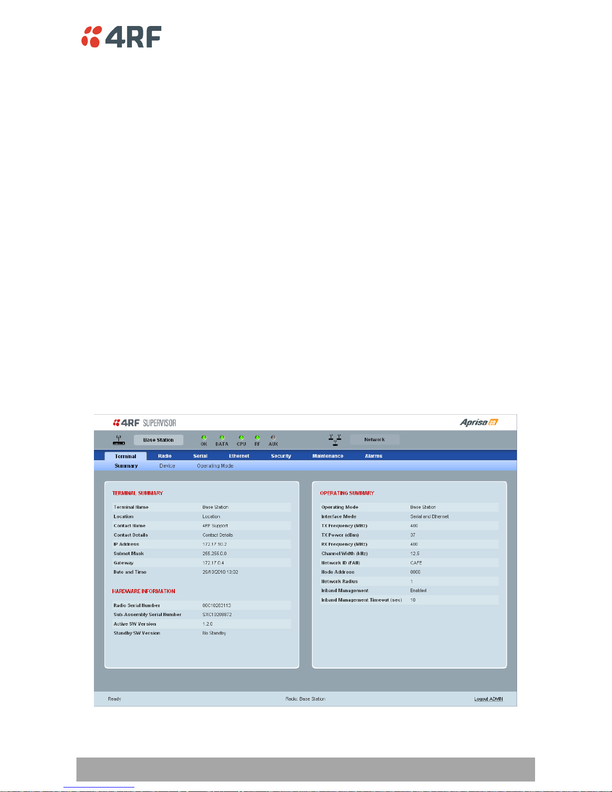
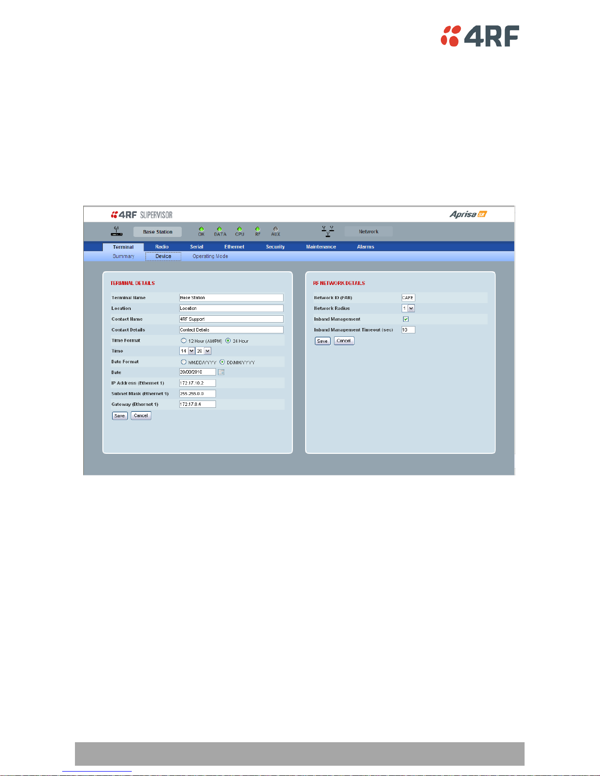
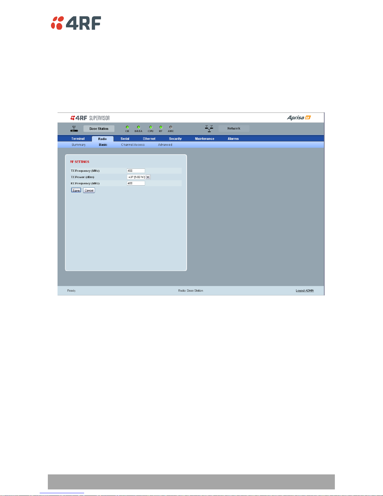
The followi ng are four examples of Supe rVi sor sc reens:
Viewing the Aprisa SR Terminal Settings
The SuperVisor software enables opera tors to view the terminal settings:
Page 25
26 | Management
Aprisa SR Product Description
Configuring the Aprisa SR Terminal Details
The SuperVisor software enables opera tors to set the terminal details including:
• Terminal Name
• Location
• Contact Name
• Contact Deta ils
• Current Date
• Ethernet port IP Address / Subnet M a s k / Gate way Address
Configuring the Aprisa SR RF Network Details
The SuperVisor software enables opera tors to set the RF Network Details including:
• Network ID (FAN)
(Field Area Network)
– four hex chars
– network ID of this base station node and its remote nodes
• Node Address
– four hex chars
– base station = 0000
– remote stations = 0001 to FFFD
• Network Radius
– sets the maximum number of hops in this network
• Inband Management
- enables Inband Management of Re motes / Repeaters
• Inband Management Timeout (sec)
- sets the Inband Management timeout period
Page 26
Management | 27
Aprisa SR Product Description
Configuring the Aprisa SR Rad io Setti ngs
The SuperVisor software enables opera tors to set the radio settings including:
• Transmit frequency MHz
• Transmit power dBm / watts
• Receive frequency MHz
• Channel type – link capacity vs channel size
Page 27
28 | Management
Aprisa SR Product Description
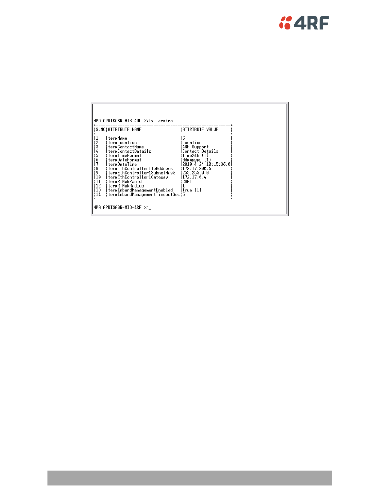
Command Line Interface
The Aprisa SR has a Command Line Interface (CLI) which provides basic product setup and configurati on.
This interface can be accessed via an Etherne t Port (RJ-45) or the Management Port (USB micro type B).
The Terminal menu is shown in the followin g picture:
Page 28

Management | 29
Aprisa SR Product Description
Managemen t Display Panel
The Aprisa SR has an optional Management Display Panel which provides on-site management and
diagnostics without the n eed fo r PC.
The features include:
• Displaying and changing frequen cies
• Enabling and disabling user interfa ces
• Displaying alarms
• Displaying performance data
• Performing upg ra de s
• Performi n g on site tests
†
Future Product Release
Page 29
30 | Management
Aprisa SR Product Description
LED Display Panel
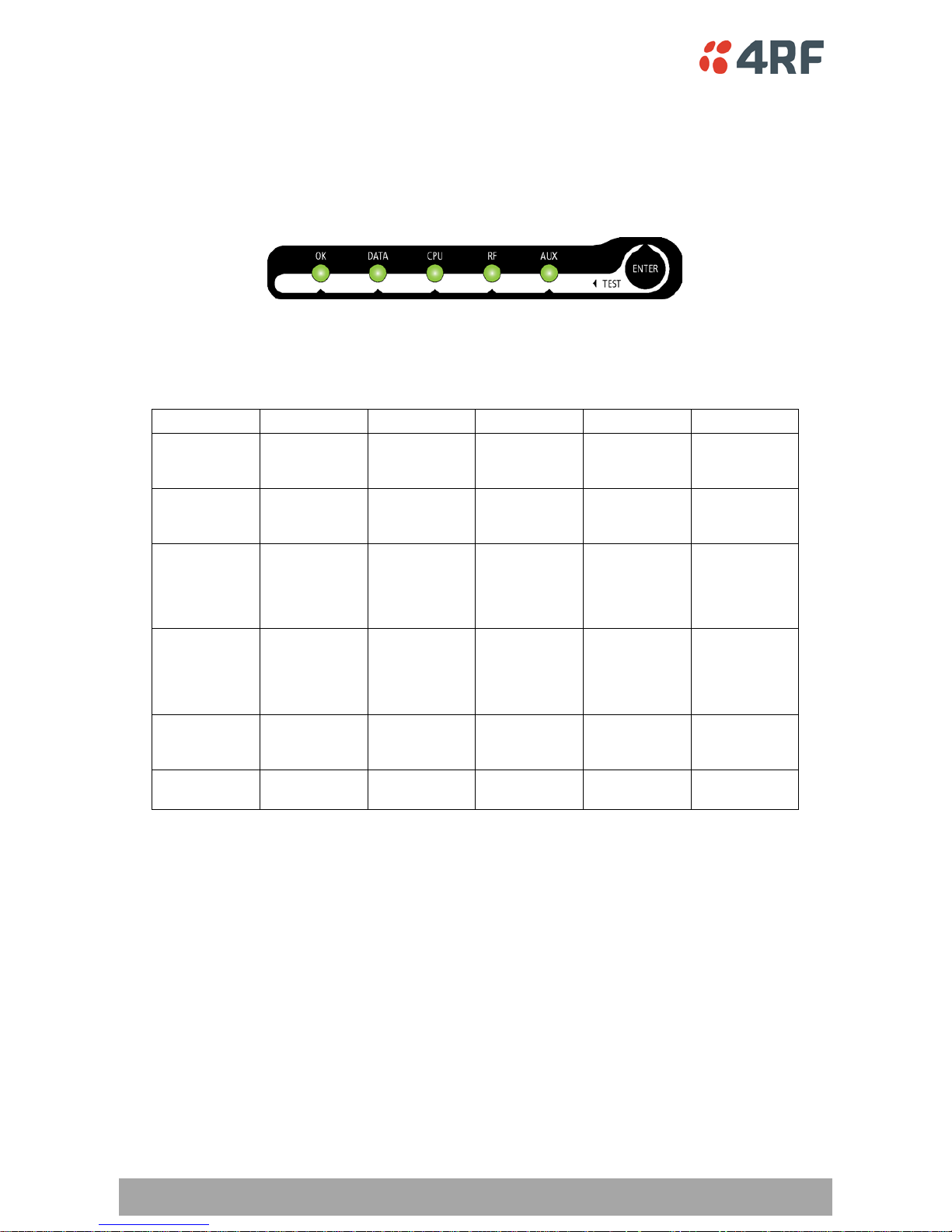
The Aprisa SR has an LED Display pan el which provides o n-site alarms / diagnostics without the need for
PC.
Normal Op era tion
In normal radio ope ration, the LEDs indicate the following conditions:
OK DATA CPU RF AUX
Solid
Red
RF path
transmit fail
alarm
Flashing
Red
Radio not
connected to a
Base Station
Radio
uncalibrated
alarm
Solid
Orange
RF path minor
alarm
Duplicate IP
address
condition
detected in
network
Flashing
Orange
Tx Data or Rx
Data on the
USB
management
port
Device detect
on the USB
host port
RF path TX is
active
Copy of Alarm
History file to
the USB drive
is in progress
Flashing
Green
Tx Data or Rx
Data on the
serial port
RF path RX is
active
Solid
Green
Power on and
functions OK
All interface
ports are OK
Processor Block
is OK
RF Path is OK
Software Upgrade
During a software upgrade, the LEDs indicate the following conditions:
• Software upgrade started - the OK LED flashes orange
• Software upgrade progress indicated by running AUX to DATA LEDs
• Software upgrade completed successfully - the OK LED solid orange
• Software upgrade failed - any LED flashing red during the upgrade
Page 30
Management | 31
Aprisa SR Product Description
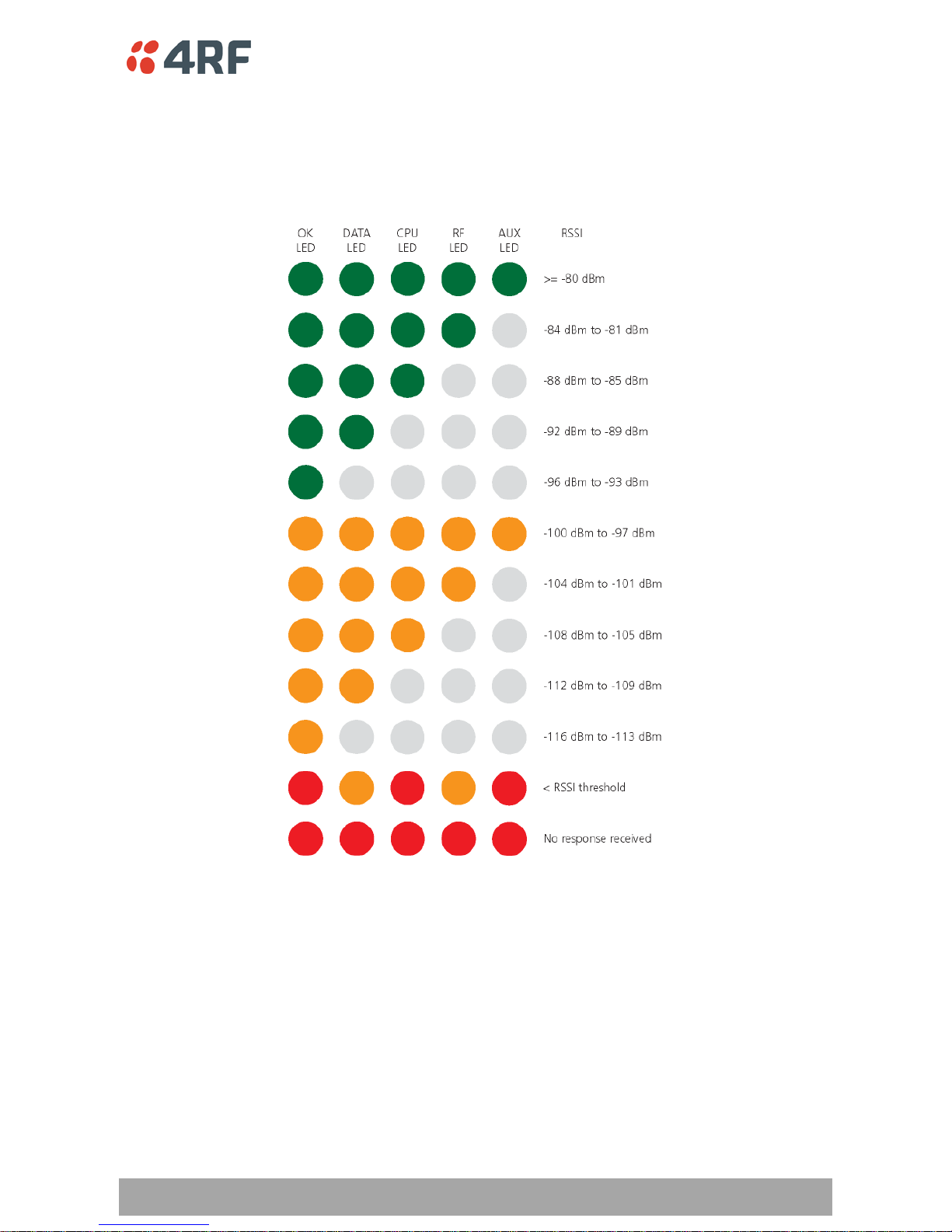
Test Mode
In Test Mode, the LED Display pa nel presents a real ti me visual displa y of the RSSI. This can be used to
adjust the antenna for optimum signal streng th.
Page 31
32 | Applications
Aprisa SR Product Description
4. Applications
This section describes sample Aprisa SR radio applications.
The followi ng appli cations are descr i be d:
• Basic point-to-multipoint application
• Advanced poin t-to-multipoint application with repeaters
• Multi-interface point-to-multipoint application
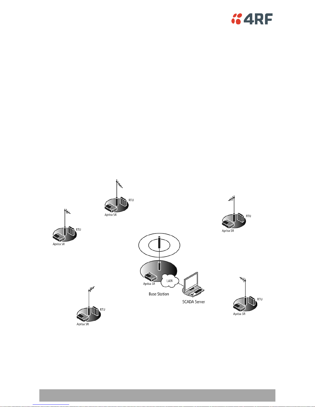
Basic point -to-multipoint application
Single base station with Ethernet SCADA data inputs to multiple g eograph ically remote s ites wi t h Et h e rne t
RTUs requiring control and data acquisition.
The base station receives Ethernet frames from the SCADA server LAN and broadc asts all Ethernet f rames
to all remote stations
Each remote site receives Ethernet frames from the RTU and unicasts over the air to the base station.
The base station uses an omni directional antenna to provide wide coverage and the remote stations are
fitted with directional Yagi antennas to provide higher gain.
Page 32
Applications | 33
Aprisa SR Product Description
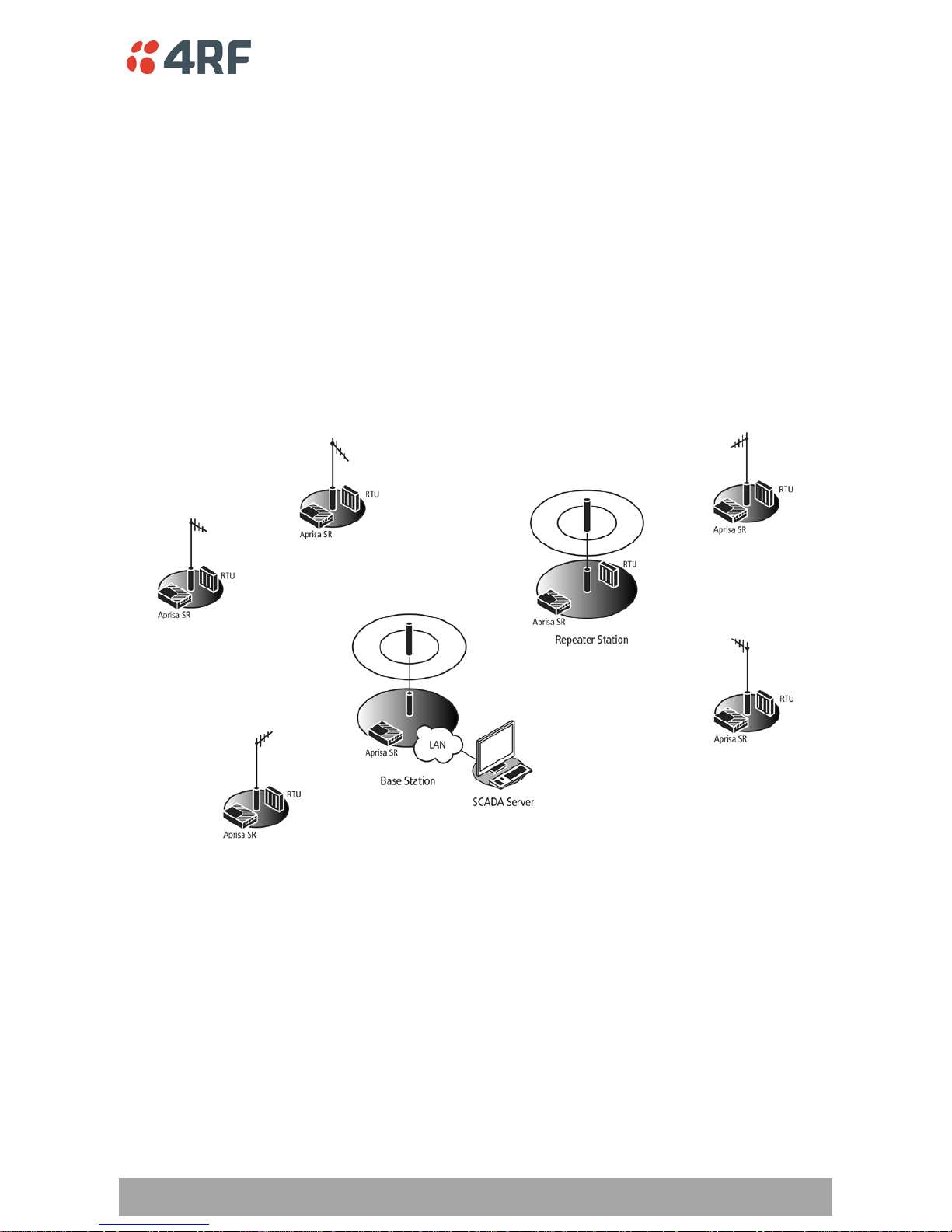
Advanced point-to-multipoint applicat ion with rep e ater
Single base station with Ethernet SCADA data inputs to multiple g eograph ically re mote s ites with Et h e rne t
RTUs requiring control and data acquisition. A repeater is deployed to service remote sites beyond the
reach of the base station.
The base station receives Ethernet frames from the SCADA server LAN and bro adcasts all Et hernet frames
to the repeater and it s remote stations.
Three remote sites have direct radio communication with the base station but the other two remote sites
operate via the repeater site.
Each remote site receives Ethernet frames from the RTU and unicasts over the air to the repeater / base
station.
The base station and the repeater station use an o mni directional antenna to provide wide coverage and
the remote stations are fitted with directional Yagi antennas to provide higher gain.
Page 33
34 | Applications
Aprisa SR Product Description
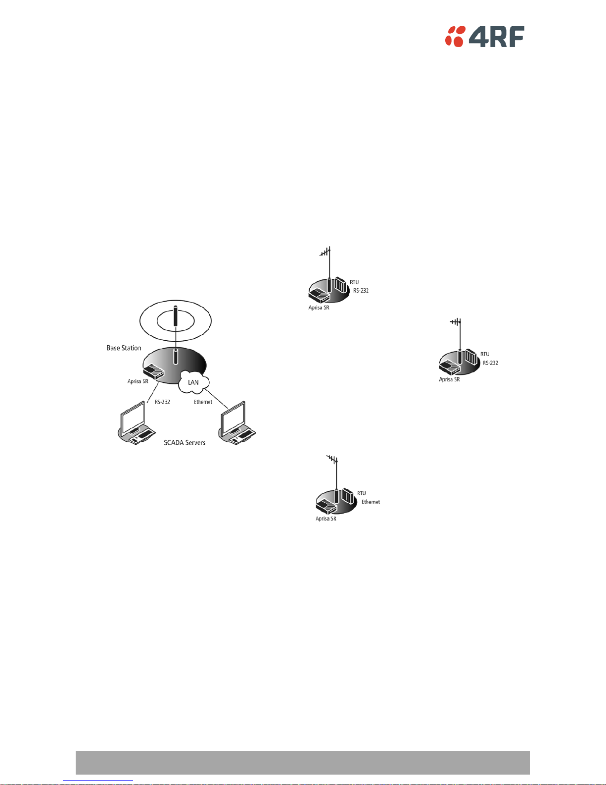
Multi-interface point-to-mu l tipoint application
Single base station with Ethernet and RS-232 SCADA data inputs to multiple geo graphically remote sites
with Ethernet and RS-232 RTUs requiring control and data acquisition.
The base station receives Ethernet / RS-232 frames from the SCADA servers and broadcasts all frames to
all remote stations
Eac h remot e site receives Ethernet / RS-232 frames from the RTU and unicasts over the air to the base
station.
The base s tatio n us es an omni directional antenna to provide wide coverage and the remote stations are
fitted with directional Yagi antennas to provide higher gain.
Page 34
Architecture | 35
Aprisa SR Product Description
5. Architecture
Product Description
There are three components to the wireless interface: the Physical Layer (PHY), the Data Link Layer (DLL)
and the Network Layer. These three layers are required to transport data across the wireless channel in
the Point-to-Multipoint (PMP) configuration. The Aprisa SR DLL is largely based on the 802.15.4 MAC layer
using a proprietary implementation.
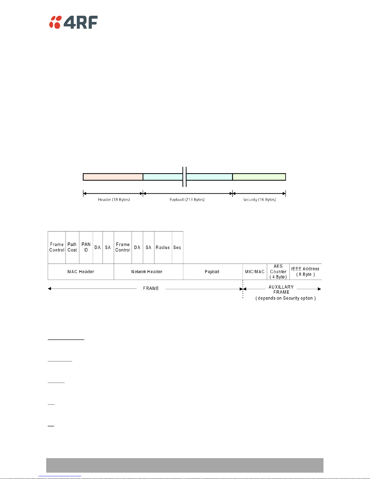
An example wireless protocol frame structure is illustrated below. This uses maximum security of
16 Bytes. The length of the header varies depending on whether the user data must be segmented. User
data will be segmented if it is larger than the wireless packet payload length. In this case, this limit is
213 Bytes. If the user data packet is larger than this, then the header increases to 20 Bytes to account for
the transport of the required segmentation and reassembly data.
This frame structure consists of:
Frame
MAC Header
The frame control field is used to maintain coexistence with IEEE 802.15.4 and ZigBee standards.
Frame Control
This field is used only during route discovery, but is present in all data frames.
Path Co st
The FAN ID may be any value between 0x0001 and 0x7fff, and represents the FAN.
FAN ID
The Destination A ddress fi eld defines the destination o f the next ho p, or 0xfff f f or br oadcast s.
DA
The Source Address field defines the source of this hop.
SA
Page 35

36 | Architecture
Aprisa SR Product Description
Network Header
The frame control field at the Network Header allows the Daintree SNA to interpret the fields correctly. In
addition, the ‘discover route’ field, in bits 6-7 determines if a unibroadcast should discover a route. Bit 15
is used to indicate an ACK is requested.
Frame Control
The Destination Add ress field in the Network Header defines the ultimate destination (not current hop).
DA
The Source Addre s s field in the Network Header defines the original source (not current hop).
SA
The Radius fie ld is de cremented each hop unti l it r eache s 0 .
Radius
The sequence number uniquely identifies the packet.
Seq
Payload
Based on the security configurati on, the payload could be either encrypted or un-encrypted.
Auxillary Frame
The Auxillary Frame fields are dependant on the security configuration chosen.
A 0-16 byte register for the Message Authentication Code.
MIC/MAC
A 4 byte counter reuired for encryption.
AE S Counter
An 8 byte IEEE MAC address.
IEEE Address
Page 36

Architecture | 37
Aprisa SR Product Description
Physical Layer
The Aprisa SR PHY uses a one or two frequency ½ duplex transmission mode which eliminates the need for
a duplexer.
Remote nodes are predominantly in receive mode with only spo radic burs ts of transmit data . This reduc es
power consumption.
The Aprisa SR is a packet based radio. Data is sent over the wireless channel in discrete packets / frames,
separated in time. The PHY demodulates data within these packets with coherent detection.
The Aprisa SR PHY provides carrier, symbol and frame synchronisation predominantly through the use of
preambles. This preamble prefixes all packets sent over the wireless channel which enables fast
synchronisation.
Data Link Layer / MAC layer
The Aprisa SR PHY enables multiple users to be able to share a single wireless channel; however a DLL is
required to manage data transport. The two key components to the DLL are channel access and hop by
hop transmission.
Channel Access
Channel access is realized in the Aprisa SR using Carrier Sense Multiple Access (CSMA). In this mode, a
pending transmission requires the channel to be clear. This is determined by monitoring the channel for
other signals for a set time prior to transmission. This results in reduced collisions and improved channel
capacity.
There are still possibilities for collisions with this technique e.g. if two radios simultaneously determine
the channel is clear and transmit at the same time. In this case an acknowledged transaction may be used.
The transmitter requests an ACK to ensure that the transmission has been successful. If the transmitter
does not receive an ACK, then random backoffs are used to reschedule the next transmission.
There are a number of parameters that can be altered for the channel access such as back off times,
number of retries etc. To enable the most efficient use of the channel these parameters will differ for
each network (largely dependent on number of radios in the network).
Hop by Hop Transmission
Hop by Hop Tran smission is rea lized in the Apris a SR by adding a MAC addres s header to th e packet. For
802.15.4, there are 2 addresses, the source and destination addresses.
Page 37

38 | Architecture
Aprisa SR Product Description
Network Layer
Packet Routing
Packet routing is realized in the Aprisa SR by adding a network address header to the packet. This contains
source and destination addresses. For the Network Layer, there are 2 addresses, the address of the
originating radio and the address of the terminating radio (i.e. end to end network). This is required for
routing pac kets across multiple ho ps e.g . PM P wit h repeaters.
The Aprisa SR uses an automated method for performing address assignment and routing information.
There are two types of packets: u nicast and bro adcast. Only the base station sends broadcasts which are
received by all remote stations. User packets are not interpreted as the radio link is transparent.
Traffic
Data originating on the Base Station is broadcast to all Repeater Stations and Remote Stations.
Data originating on a Remote Station is unicast to the Base Station only. This can be via multiple Repeater
Stations.
Data originating on a Repeater Station is unicast to the Base Station only.
Data originating on a serial port is terminated on a serial port and data originating on an Ethernet port is
terminated on an Ethernet port only.
User Traffic
User traffic is prioritized depending on the Serial and Ethernet Data Priority options.
If the Serial and Ethernet Data Priority options are equal, then first come first served is invoked.
Repeater stations repeat traffic also on a first come first served basis.
Management Traffic
Ethernet Management Traffic has the same priority as Ethernet User Traffic but if the radio is not licensed
for Ethernet, the Ethernet Data P r iority i s set to Low.
Page 38
Architecture | 39
Aprisa SR Product Description
Product Operation
Carrier Sense Disabled
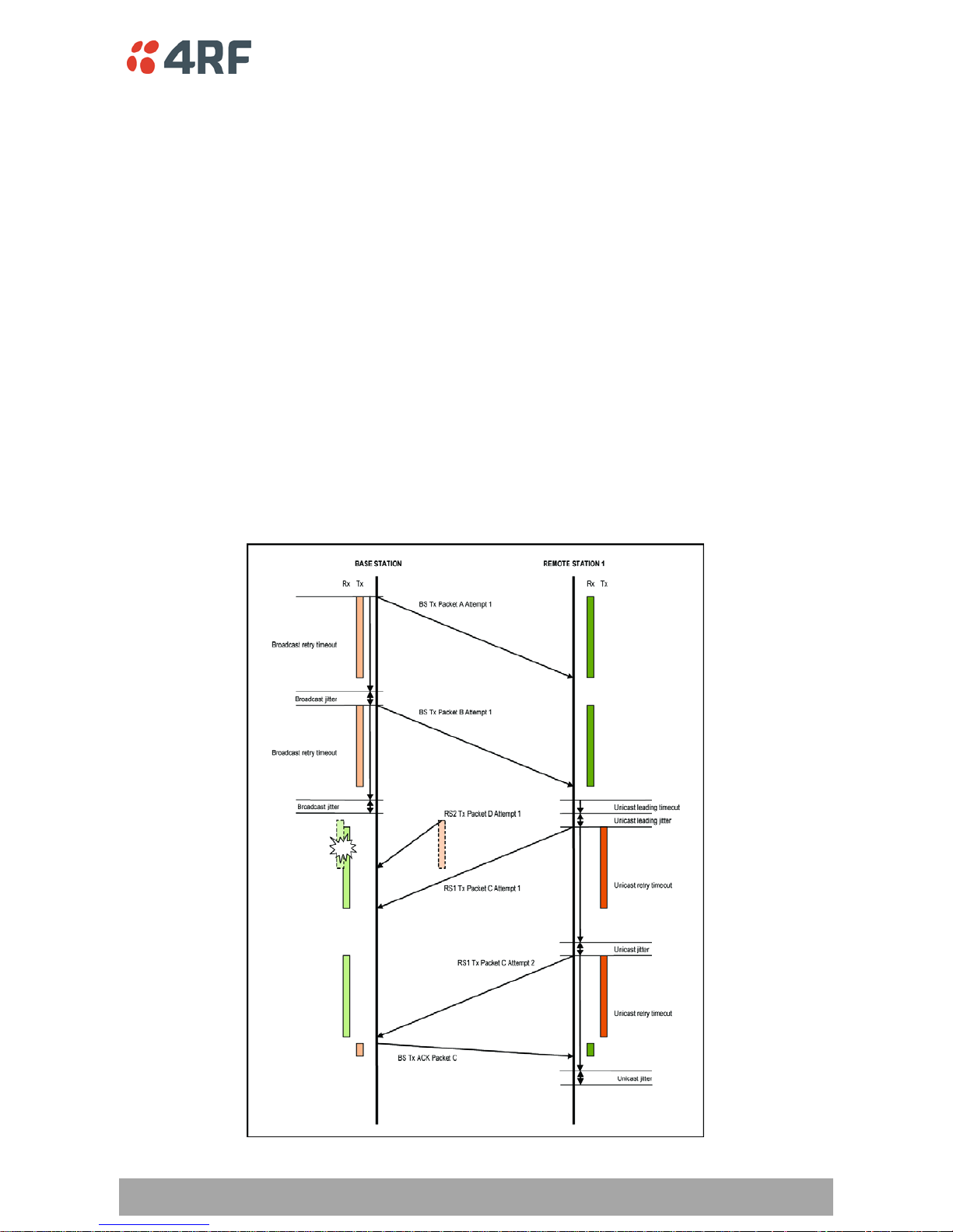
The following timing diagram illustrates two transactions with Carrier Sense disabled on the Remote
Stations.
1. The Base Station broadcasts 2 packets to all Remote Stations.
The Base Station uses default settings e.g. 1 attempt. In this example, the 2
nd
packet (packet B) arrives
over the wired interface at the Base Station for transmission over the air before the 1
st
packet (packet A)
has left . The 2
nd
packet is queued. The timing diagram illustrates that the retry timer is used to schedule
the 2
nd
packet in the same way as a 2nd attempt would be queued.
2. Remote Station 1 attempts to send a packet (packet C) to the Base Station without the use of carrier
sense.
In this case, a second Remote Station (Remote Station 2) also attempts to send a packet (packet D) to the
Base Station at approximately the same time. In this case the 2 packets collide and the Base Station does
not reply with an ACK. The Remote Station unicast retry timer times out and the 2
nd
attempt is sent. This
attempt is successful and an ACK is received.
In this case, channel access is ALOHA.
Page 39
40 | Architecture
Aprisa SR Product Description
Carrier Sense Enabled
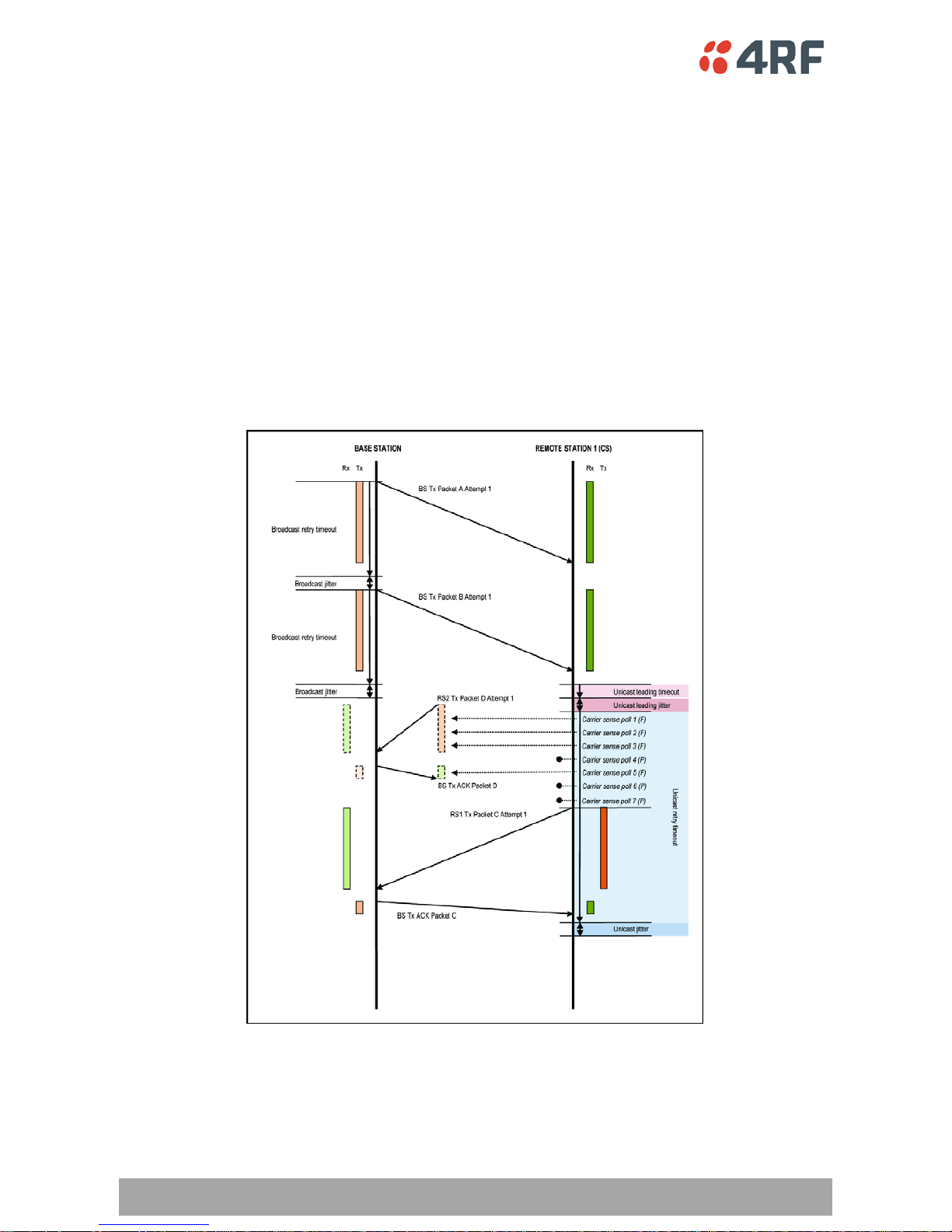
The following timing diagram illustrates the same transactions with Carrier Sense enabled on the Remote
Stations. Transmit packets are depicted as orange blocks and received packets are depicted as green
blocks.
1. The Base Station broadcasts 2 packets to all Remote Stations.
In this case, the transactions are identical to the previous example.
2. Remote Station 1 attempts to send a packet (packet C) to the Base Station with the use of carrier
sense.
Here the Remote Station detects that the channel is being used by Remote Station 2. The carrier sense
polls the channel and requires 2 consecutive channel clear assessments before the channel is accessed.
This enables the carrier sense system to detect a possible ACK. This is illustrated above with one of the
carrier sense polls (poll 4) passing as it dete ct s th e gap bet ween packet D and its associa ted ACK.
Page 40
Architecture | 41
Aprisa SR Product Description
Repeater Timing for Base Station to Remote Station Transactions
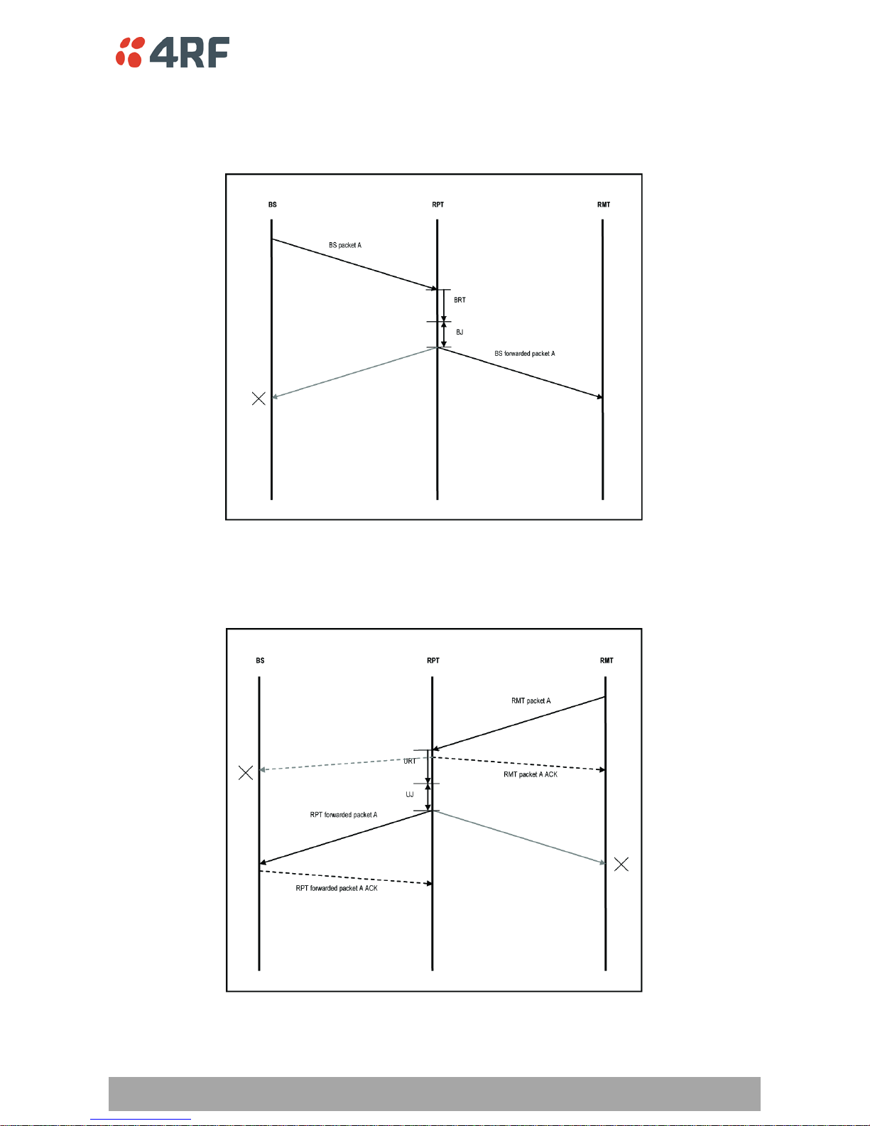
The following timing diagram illustrates repeater timing for Base Station to Remote Station transactions.
Packets are scheduled by the Broadcast Retry Timeout and Broadc a st Jitter parameters.
Repeater Timing for Remote Station to Base Station Transactions
The following timing diagram illustrates repeater timing for Rem ote Station to Base Station transactions.
Packets are scheduled by the Unicast Retry Timeout and Unicast Retry Jitter parameters.
Page 41
42 | Architecture
Aprisa SR Product Description
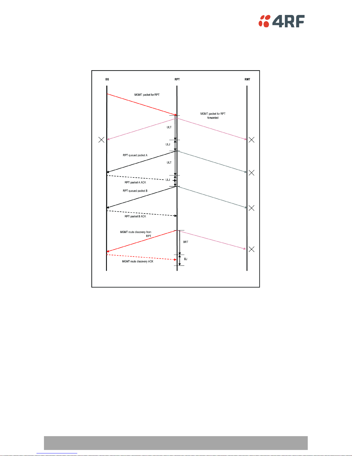
Repeater Timing for Queued Packets at the Repeater Station
The following timing diagram illustrates repeater timing for queued packets at the Repeater Station.
Packets are scheduled by the Unicast Leading Timeout and Unicast Leading Jitter parameters.
Page 42

Architecture | 43
Aprisa SR Product Description
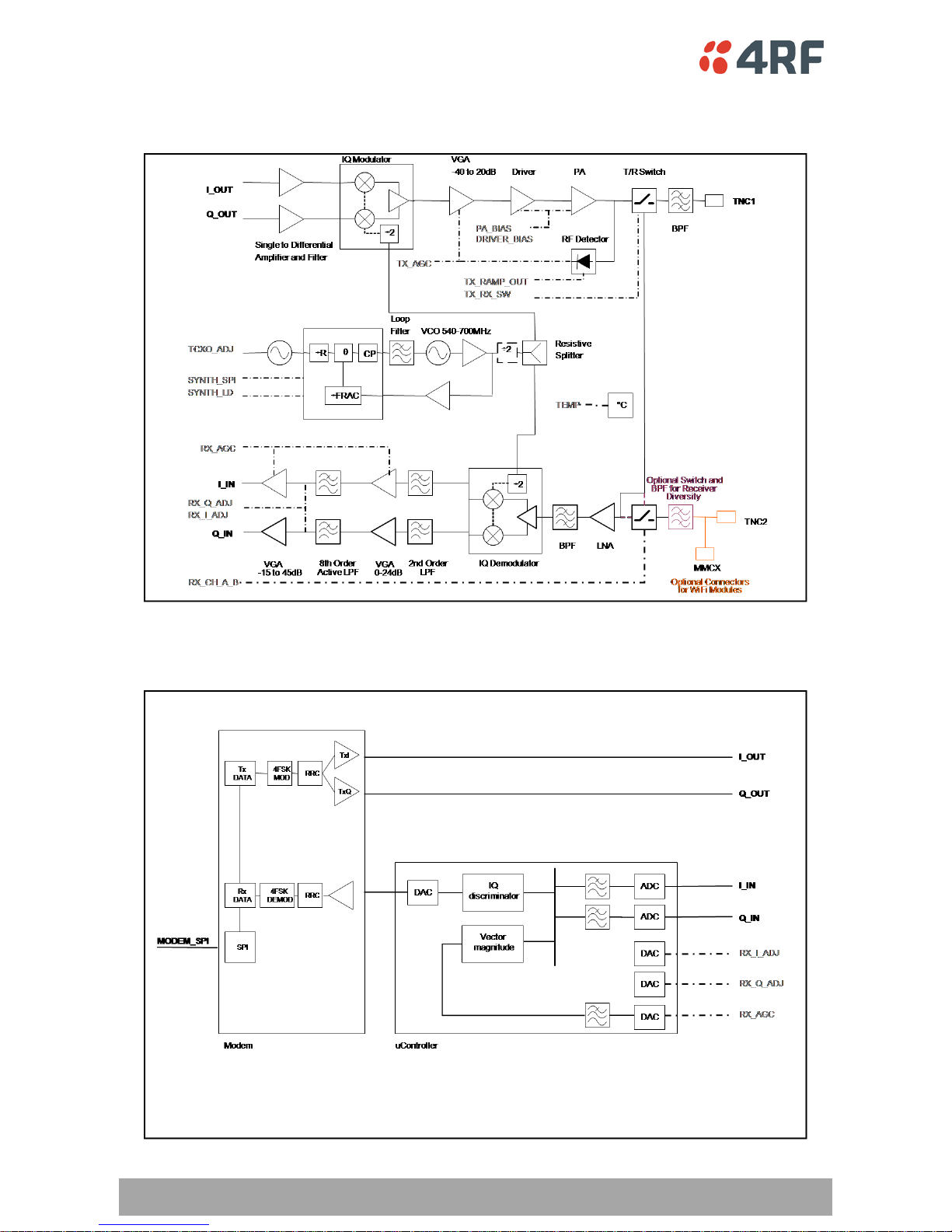
Product Architecture
The following are the key components of the Aprisa SR design:
High performance ΣΔ fractional-N synthesizer
• 2x output frequency VCO for minimal pulling during transmit
• Wideband design electronically tunes over entire band
• Tx and Rx LO operate on the same frequency, reducing the tuning range of the VCO and
therefore better noise performance
• Proven ul tr a low noise te c h nology – 50dB SNR easily achieved
Direct IQ modulation
• Simple IQ modulat io n line up reduces part count and improves MTBF
• No mixing stages so no spurious responses present at the transmitter output
Tx turn-on time limited primarily by PA rampi n g
• Robust, closed-loop power control – fast, accurate power ramp up and down
MOSFET PA device
• High efficiency (>60% PAE at 8 W)
• Very low thermal resistance (2.5°C/W)
Di rect IQ do wn-conversion
• Excellent Intermodulation distortion characteristics as channel filter can be placed directly
after the mixer without impa cting noise figure
• High Q active channel filtering helps achieve selectivity performance
• Low parts c ou n t and no cry sta l filters help to keep receiver performance extremely stable over
temperature
Integrated heat sink
• Limits number of mechanical interfaces
• Fin design optimized for natural convection
Monitoring and software control
• Temperatu re control loop shuts down transmitter when the temperature exceeds continuous
ope ration at 7 0°C
• Monitoring of RSSI and PA current help to make sure the RF hardware is functioning to
specification
Page 43
44 | Architecture
Aprisa SR Product Description
Radio Block Diagram
Modem Block Diagram
Page 44

Contact Us | 45
Aprisa SR Product Description
6. Contact Us
 Loading...