

Crimestopper Security Products CS-2008PC User Manual

CS-2008PC SecurLinc™
INSTALLATION & OPERATING INSTRUCTIONS
*NOTE: There are several features of the CS-2008PC system that can only be accessed and/or programmed
by using optional SecurLinc™ PC software and data cable via the system’s expansion port via a Personal
Computer: An expansion kit is available which includes Software, PC linc cable and a power supply (SLA-50)
• Assigning the amount of time for a “Timed” Auxiliary output channel.
• Assigning Self-start temperature and voltage-drop thresholds (when using the remote start expansion
module).
• “Secure Disarm” using a 4-press transmitter button sequence.
• Inputs & Outputs testing and diagnostics of main system
• Inputs & Outputs testing of Data Linc expansion modules i.e. Remote Start, 2-Way pager, & Aux. channel
module.
• Quick & Easy option programming
• Erasing transmitter codes
• Adjusting Glow plug delay time, Voltage Drop Threshold
ADVANCED REMOTE CONTROL ALARM SYSTEM
BEFORE BEGINNING, check all vehicle manufacturer cautions and warnings regarding electrical service (AIR
BAGS, ABS BRAKES, ENGINE COMPUTERS, BATTERY etc.).
WE RECOMMEND the use of a VOLT/OHM METER to test and verify wiring circuits. Test lights or illuminated
probes can cause damage to on-board computer or engine management systems.
DO NOT exceed maximum output ratings or damage may occur. Electrical current limits for this alarm are
listed where applicable on the system diagram (Pg. 16). If you are unsure about the current load, of a specific
circuit on your vehicle, measure the load first with an amp-meter before connecting.
WE RECOMMEND that the MAIN SYSTEM FUSE be REMOVED before jump starting, using a battery
charger, or changing the battery. A voltage surge or high boost condition could damage alarm circuits.
DO NOT ROUTE ANY WIRING THAT MAY BECOME ENTANGLED with brake, and gas pedals, steering
column, or any other moving parts in the vehicle.
TECH SUPPORT
Mon-Fri 8:00 AM-4:30 PM Pacific Time
(800) 998-6880
Website: www.crimestopper.com
Email: email@crimestopper.com
REV. A 02/2003 SW:
PRE-INSTALLATION CAUTIONS & WARNINGS
This device complies with FCC Rules part 15.
Operation is subject to the following two conditions: 1)
This device may not cause interference, and (2) this
device must accept any interference that may be
received, including interference that may cause
undesired operation. The manufacturer is not

Pre-Installation Cautions & Warnings…….…………………………………………………………..………………1
Control Module & Component Mounting…………………..……………………….………………………..…….2-3
Wiring Descriptions.…………………………………………………………….……………………….……….…...3-4
System Wiring Diagrams #1 & #2……………………………………………………………….…………….…….5-6
Shock Sensor & LED / Valet POD……………………………………………………………………………………..7
Power Door Lock Wiring & Diagrams…………………….………..……………………………….………………8-9
Remote Transmitter Programming…………………………………………………………………………..………10
2-Vehicle Programming………………………………………………………………………………………..………10
Option Programming…………………………………..………….……………………………….…………….…10-13
Option Reset (Restore Defaults…………………….……………….……………………………….…………….…14
Customized Personal Override Code………………………….……………………………….……………………14
Secure Disarm Feature…………………….…………………….……………………………….……………………14
Hands-Free Transmitter (Optional)……………………………………………………………..………..………15-16
Carjack Protection Features…………………………………………………………………………………….…….16
Remote Control Diagram………………………………………………………………………………………………17
Alarm Operation……………………………………………………………………………………………….…….17-19
Remote Less Disarm “Beach Mode”…………………………………………………….…………………….…….19
Prior Intrusion Alert (Diagnostic)……….……………………………………………………………………..……..19
CONTROL MODULE MOUNTING
DO NOT Mount the control unit or wiring harness where they can become entangled with moving parts
such as brake/gas/clutch pedals, or the steering column! The alarm control module should be mounted in
a concealed location. The Placement of the module will affect the distance from which the remote transmitter
can control the unit. The antenna wire should be routed away from any metal if possible. Do not alter the
length of the antenna wire or route it with other wires. Do not ground the antenna wire. Fasten the module to
a bracket or wire harness using the cable ties provided.
Underdash Mounting: If you are locating the control unit underdash, mount it as high as possible, not easily
located by an intruder.
Driver’s Side Underdash mounting provides an easy location for wiring most of the system’s connections,
however this is a common location for an intruder to check for an alarm after breaking into the vehicle. The left
side of the vehicle may contain more metal and or wiring that will create interference and decrease the
operating range of the system.
Passenger Side underdash is a good location, however some extra wiring may be needed to extend wires
across from the driver’s side.
Under-seat / Center Console mounting is also a possibility, but NOT RECOMMENDED. The system’s
transmitter range will be reduced by the metal structures of the seat or center console and the unit may also be
exposed to moisture from spilled drinks etc. Moisture or water damage is not covered under the warranty and
will be subject to repair charges. Under seat or console mounting will create more difficulty if you need to
access the unit for service or want to add-on features or connections later. Use this location as a last resort.
TABLE OF CONTENTS

SIREN: Mount the siren under the hood to an inner fender-well, wheel-well, or other body surface with the
open end facing downward. Run the red siren wire through the firewall using a rubber grommet. Ground the
black to the body metal near the siren or you can use one of the siren’s mounting screws for a ground.
LED/VALET POD: This system includes a unique assembly that houses the LED and the
VALET/PROGRAMMING button. See page 7.
Dual-Stage Shock Sensor: Mount shock sensor with wire ties to an under dash wire harness or fasten with
screws to firewall or side paneling. Use the adjustment screw to set the sensitivity of the sensor. One screw
adjusts both levels.
WIRING
PIN 1: BLACK WIRE: INPUT FROM VALET SWITCH
Connect to the 2-pin blue Valet Button harness to the 2-pin socket in system’s the main wire loom
PIN 2: BLUE WIRE: (-) HOOD/TRUNK TRIGGER INPUT
Input trigger for a grounding hood and/or trunk pin switches. Connect to a hood and/or trunk pin switch that
reads ground when open. If no existing switches or circuits are available, install new grounding pin switches if
desired. To avoid water leakage and failure resulting from rust, DO NOT mount switches in water pathways.
PIN 3: WHITE/RED WIRE: (-) AUX REMOTE OUTPUT #2 (Optional, Programmable)
Connect to the negative activation circuit of an auxiliary device or accessory. This output can be configured for
PULSED, TIMED, or LATCHED. See Programming Options Section for more information.
PIN 4: VIOLET WIRE: (+) DOOR TRIGGER INPUT
Connect to Positive type door switches that show +12 Volts when the door is open and Ground when the doors
are closed. Positive type door switches are found on many Ford, Lincoln and Mercury vehicles.
PIN 5: YELLOW WIRE: IGNITION SWITCHED “ON” +12 VOLTS INPUT
Connect to an Ignition Wire (or Fuse in the fuse box) that shows +12 Volts power when the key turned “On”,
when the car is “Cranking”, and when the car is running.
PIN 6: BLUE/BLACK: SENSOR #2 INPUT
Connect to the trigger wire of an optional second alarm sensor. The system main wiring loom is preassembled with an extra 4-pin sensor connector for the additional sensor. (Pre-wired Sensor #2 harness
colors: Red: 12+, Black: Ground, Blue: Pre Warn, Blue/Black: Trigger input)
PIN 7: GREEN WIRE: (-) DOOR TRIGGER INPUT
Connect to Negative type door switches that read ground when a door is opened and 12 volts when all doors
are closed or connect to the circuit that triggers the vehicle’s dome light.
PIN 8: ORANGE: SHOCK SENSOR INPUT
Connects to the trigger wire of the dual-stage shock sensor sensor. The system main wiring loom is preassembled with a 4-pin sensor connector for the shock sensor. Simply mount the shock sensor, plug in, and
adjust. (Pre-wired Shock sensor harness colors: Red: 12+, Black: Ground, Blue: Pre Warn, Orange Trigger
input)
PIN 9: BLUE WIRE: (-) PRE-WARN INPUT
Warn-away input for both Shock Sensor and Sensor #2. Pre-wired to 4 pin mini harnesses, no connection
required.
PIN 10: BLACK WIRE: CHASSIS GROUND
This BLACK WIRE must be connected to the CHASSIS METAL of the VEHICLE. Scrape away any paint or
debris to ensure a good connection. Use a star washer to ensure a good ground connection. Keep the
Ground wire short.
PIN 11: BROWN WIRE: (+) SIREN OUTPUT (3 Amp Max.)
Connect to the RED wire coming from the siren in the engine compartment.
COMPONENT MOUNTING

WIRING
PIN 12: ORANGE WIRE: NEGATIVE ARMED OUTPUT – Starter Disable (500mA Ground, Optional)
This wire becomes a (-) Ground output when system is armed. This output can be used for optional
accessories such as window roll up modules, scanner LED’s, voice modules, etc.
PIN 13: BLUE: NEGATIVE UNLOCK OUTPUT / POSITIVE LOCK OUPUT.
PIN 14: GRAY WIRE: (-) AUX REMOTE OUTPUT #1 (Optional, Programmable)
Connect to the negative activation circuit of a power trunk, hatch, or auxiliary device. This output can be
configured for PULSED, TIMED, or LATCHED. See Programming Options Section for more information.
PIN 15: GREEN: NEGATIVE LOCK OUTPUT / POSITIVE UNLOCK OUPUT.
PIN 16: BLUE/WHITE WIRE: (-) PASSENGER DOOR UNLOCK OUTPUT (Optional, requires relay)
Connects to unlock circuit for passenger door(s) when using separate driver’s door unlock option. See
SEPARATE DRIVER’S DOOR UNLOCK WIRING for configuration options.
PIN 17: BROWN/WHITE WIRE: (-) HORN HONK / CHIRP OUTPUT (Optional, may require a relay)
Connect to the Negative Horn Trigger wire for a horn honk during an alarm trigger. Horn activation wire is
usually located near the steering column. If the Horn circuit requires +12Volts, then a relay is required.
RELAY WIRING: Connect the Brown/White wire to terminal 85 of a relay. Connect terminals 86 and 87 to +12
Volts constant power. Connect terminal 30 to the Positive horn activation circuit.
PIN 18: BLACK/YELLOW WIRE: (-) AUX REMOTE OUTPUT #3 (Optional, Programmable)
Connect to the negative activation circuit of an auxiliary device or accessory. This output can be configured for
PULSED, TIMED, or LATCHED. See Programming Options Section for more information.
PIN 19: RED/BLACK WIRE: LED OUTPUT
Connect to the 2-pin Red LED harness to the 2-pin socket in system’s the main wire loom
PIN 20: BLACK/WHITE WIRE: DOME LIGHT ILLUMINATION OUTPUT 10A On-Board Relay (+ or -)
Connect this wire to the vehicle’s dome light activation circuit (May also be connected at the same point as the
Door Pin Switch input). This output will turn on the vehicle’s dome light when the system is disarmed using the
remote control. The +/- polarity of this output of this wire can be changed moving a jumper inside the control
module housing. DEFAULT output is Negative.
PIN 21: WHITE WIRE: FLASHING PARKING LIGHT OUTPUT 10A On-Board Relay (+ or -)
Connect this wire to the vehicle’s parking light circuit. The +/- polarity of this output of this wire can be
changed moving a jumper inside the control module housing. DEFAULT output is Positive.
PIN 22: RED WIRE: +12V POWER INPUT (15 Amp Fuse)
Connect to a +12 Volt source with the supplied fuse and fuse-holder. We recommend the Battery positive
terminal.
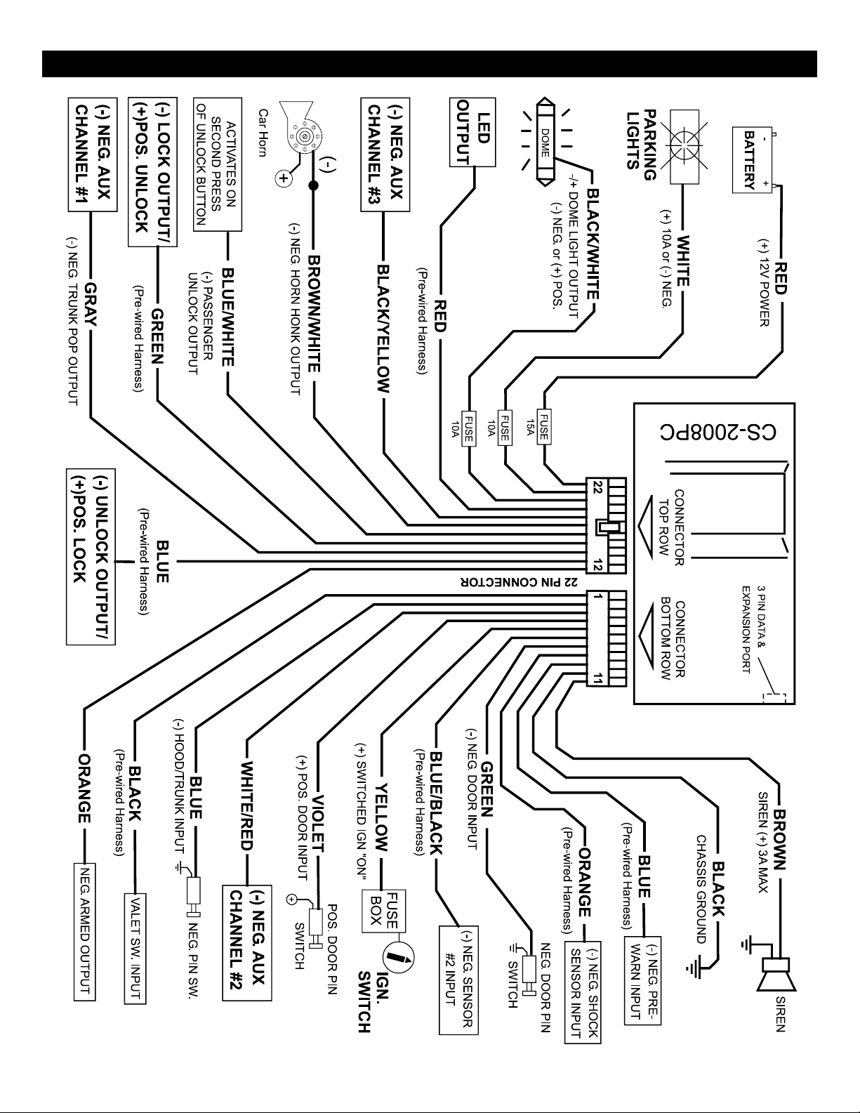
SYSTEM WIRING DIAGRAM #1
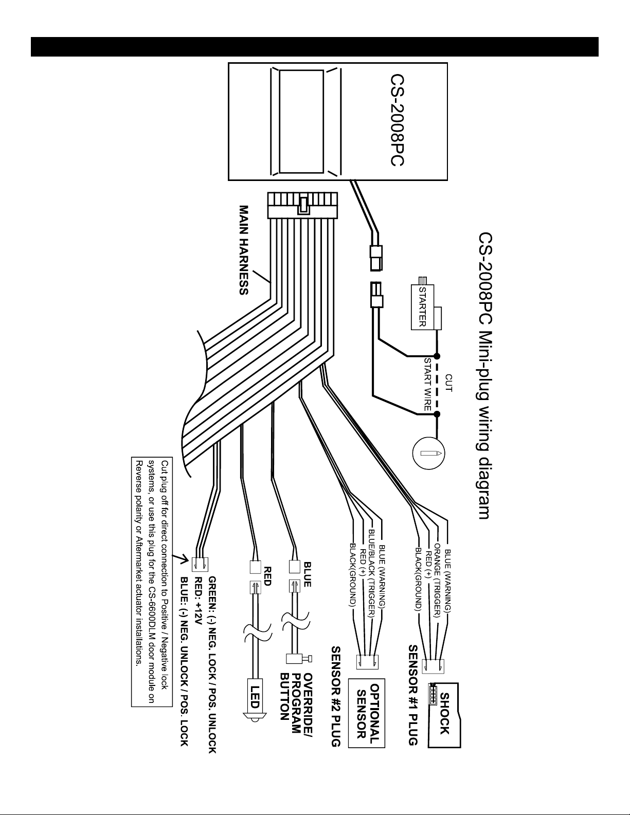
SYSTEM WIRING DIAGRAM #2
 Loading...