

Crimestopper Security Products CS-2004TW2 User Manual
CS-2004TW1 with 2-Way AM/FM LED Pager/Remote & 1-Way ‘Sidekick’ Remote
CS-2004TW2 with 2-Way AM/FM LCD Pager Remote & 1-Way ‘Sidekick’ Remote
CS-2004DC II with two 1-Way Remotes
INSTALLATION & OPERATING INSTRUCTIONS
CONGRATULATIONS on your choice of a Security System by Crimestopper Security Products Inc. This booklet
contains the information necessary for installing, using, and maintaining your 2004TW1/2 or 2004DC II alarm
system. If any questions arise, contact your installation dealer or Crimestopper Security Products Inc. at the Tech
Support number below.
This installation book is designed for the installer or individual with an existing understanding of automotive electrical
systems, along with the ability to test and connect wires for proper operation. To ease installation, we suggest that
you READ THIS MANUAL before beginning your installation. This book is provided as a GENERAL GUIDELINE
and the information contained herein may differ from your vehicle.
*IMPORTANT INFORMATION: Primary and Optional Features
-PRIMARY: These are features that must be connected in order for the system to operate properly i.e. Siren,
L.E.D., Power, Ground, Door Pin, Flashing Lights etc.
-OPTIONAL: There are features to be connected only if desired or agreed upon by the customer and the installing
dealer (i.e. Door Locks, Starter Disable, Hood/Trunk Protection and Auxiliary Remote Outputs etc.). These features
may also require additional parts and/or labor fees. Consult with your installer beforehand to be sure of what is
going to be installed with your particular system.
TECH SUPPORT
(800) 998-6880
Hours: M-F 8:00AM-4:30PM
Pacific S td. Time
REV F 5.26.2005
authority to operate the equipment.
SERIES II
This device complies with FCC Rules part 15. Operation is subject to the following two
conditions: 1) This device may not cause interference, and (2) this device must accept any
interference that may be received, including interference that may cause undesired
operation. The manufacturer is not responsible for any radio or TV interference caused by
unauthorized modification to this equipment. Such modification could void the user's

TABLE OF CONTENTS
Installation Cautions & Warnings…….………………………………………………………..…………………………………...………………2
Control Module / Component Mounting….………………………..………………………………………………………………….…………..3
Wiring……..…………………………………………………………..……………………………………………………………………………….3-7
Power Door Lock Wiring...…………………………………….…………………………………..……………..……..…………………………8-9
Starter Disable Wiring…………………………..…..………………………………………………………………………………………..……..10
System Wiring Diagram………………….………………..………………….…………………………………………………………….………11
CS-2004TW1/2 Antenna Diagram………...…………………………………………………………………………………….………….…...…12
Option Programming……………..……………………………………………………………..…………………………….……..…….……13-15
Programmable Option Reset……………………….....……….…………….……………………………………………….…………………...16
CS-2004TW1/2 & CS-2004DCII Remote Programming…………………..….…..…………………………………………….…....…….16-17
Remote Operation………………………………………,…………………….………………..….……………………………………….……...18
Transceiver/Pager Remote……………………………,…………………….………………..….……………………………………….……...19
Low Battery Warning – LCD Remote……………………………………………………………………………………………………………20
Setting the Clock (2-Way LCD Remote)………………………………………………………………………………………………………..20
LCD Panel Functions Shown..…………………,…………………….………………..….……………………………..……….………….20-21
Operation…………………………………………………,…………………….………………..…………………………………….….……21-24
2 Vehicle Operation…………………………………,…………………….………………..….…………………………..………….……........25
Carjack Operation…………………………………………………………….…………………..……………………….…..…………………..26
INSTALLATION CAUTIONS & WARNINGS
BEFORE BEGINNING, check all vehicle manufacturer cautions and warnings regarding electrical service (A IR
BAGS, ABS BRAKES, AND BATTERY).
TO PREVENT A POSSIBLE DEAD BATTERY remove vehicle dome light fuse while working on the vehicle. MAKE
CERTAIN TO RE INSTALL FUSE PRIOR TO TESTING FOR DOOR TRIGGERS.
DO NOT EXCEED MAXIMUM OUTP UT RATINGS! - SERIOUS DAMAGE MAY OCCUR. LIMITS FOR ALARM
FUNCTIONS ARE LISTED WHERE APPLICABLE.
2

REMOVE MAIN SYSTEM FUSE(S) before jump starting the vehicle or charging the battery at high boost. DAMAGE
MAY OCCUR TO S YSTEM IF PROPER PRECAUTIONS ARE NOT OBSERVED.
DO NOT ROUTE ANY WIRING THAT MAY BECOME ENTANGLED with brake, and gas pedals, steering column,
or any other moving parts in the vehicle.
CONTROL MODULE / COMPONENT MOUNTING
DO NOT Mount the control unit or wiring harness in the engine compartment or anywhere they can become
entangled with moving parts such as brake/gas/clutch pedals, or the steering column. The alarm control module
should be mounted in a concealed location. The antenna wire should be routed away from any metal if possible.
Do not alter the length of the antenna, ground it, or route it with other wires.
SIREN MOUNTING: Mount the siren under the hood to fender-well or other body surface with the open end facing
downward. Run the red siren wire through the firewall using a rubber grommet. Ground the black wire to the body.
LED: Mount the LED in a visible location on the dashboard or console.
Shock Sensor: Mount the included shock sensor with wire ties to an under dash wire harness or fasten with screws
to firewall or side paneling.
Override/Program Button: Mount the Override/Program push-button in a hidden but accessible location. It is used
for emergency disarm without the use of the transmitter and for programming certain features.
WIRING
RED WIRE: +12V POWER INPUT (15 Amp Fuse)
Connect to a +12 Volt source with the supplied fuse and fuse-holder. We recommend the connection to be at the
Vehicle’s Battery Positive Terminal.
BLACK WIRE: CHASSIS GROUND
THIS WIRE MUST BE CONNECTED TO THE CHASSIS METAL OF THE VEHICLE. Scrape away any paint or dirt
to ensure a good connection.
YELLOW WIRE: IGNITION SWITCHE D “ON” and “START” +12 VOLTS
Connect to a (+) Ignition wire that shows +12 Volts when the key is in both the “ON” and “Cranking” positions.
ORANGE WIRE: (-) NEGATIVE ARME D OUTPUT
This wire becomes a Negative Ground output when system is armed. This output can be used for additional starter
disable relays or to activate other devices such as scanner LED’s, window modules, voice modules etc.
+
+12 V
PINK
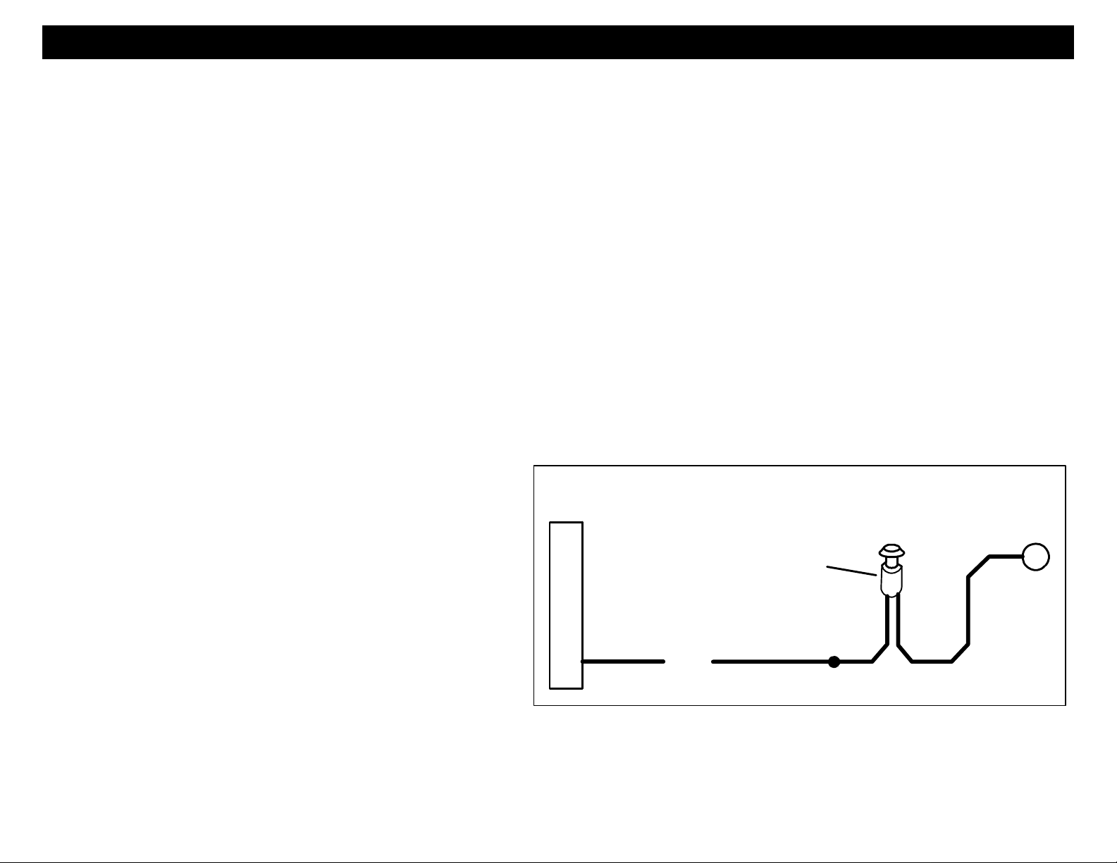
OPTIONA L CAR JACK WIRING: SWITCH
HIDDEN BUTTON or
TOGGLE SWITCH
(Not Included)
WIRING
WHITE WIRE: +12V FLASHING PARKING LIGHT OUTPUT (10A)
Connect to the switched parking light wire at back of light switch or connect directly to one of the parking lights at the
front of the vehicle. E uropean vehicles may require additional parts due to separate left and right circuits.
BROWN WIRE: (+) SIREN OUTPUT (3 Amp Max.)
Connect to the siren’s RED wire. Connect the Siren’s Black Ground wire to the chassis close to the siren.
BLUE WIRE: (-) HOOD/TRUNK TRIGGER
The Blue wire is used for a grounding hood pin switch, trunk pin or both. Connect to existing hood and trunk pin
switches that read ground when open. If no existing switches are available, install new pin switches if desired.
GREEN WIRE: (-) DOOR TRIGGER
Connect to Negative type door switches that read ground when a door is opened and 12 volts when all doors are
closed. In the case of isolated door triggers, you may need to run additional wires from other doors OR go directly
to the dome light.
VIOLET WIRE: (+) DOOR TRIGGER
Connect to P ositive type door switches that show +12 Volts when the door is open and Ground when the doors are
closed.
PINK WIRE: (+) CARJACK INPUT
Connect to a push button, toggle switch, or to a +12
Volt source to selectively activate Car Jack protection
features - See diagram on next page for example
wiring configuration. This wire is used to activate a
passive carjack trigger even if the Carjack features
are not turned on in the programming options. A
Carjack countdown will begin under the following
conditions: Ignition is ON (vehicle is running), the
button or toggle switch is pressed, and a door opens
& closes. Upon these 3 events, in that order, the
alarm will start a Carjack countdown. See “Carjack protection” section on page 19.
4
WIRING
GRAY WIRE: (-) NEG. INPUT [COIL] FOR ON-BOARD 15A RELAY (Term #85, Step #1)
This input controls the function of an on-board relay. Connect to any desired Auxiliary or Optional wire from the
Brown 3-pin output harness. Connect the Gray wire to the Orange/Black for Dome light illumination, Brown/Black
for Auxiliary 1 or Red/Black for Auxiliary 2 function. (See diagram, next page)
WHITE/RED WIRE: (+/-) INPUT SOURCE FOR ON-BOARD 15A RELAY (Term #87, Step #2)
Connect to a +12 Volt source or Chassis Ground depending on the polarity of the circuit you are going to auxiliary
circuit or function you are going to activate with the Black/W hite output wire. Connect to +12V for Positive Circuits
or Chassis Ground for Negative circuits. This wire must be the same polarity as the Black/White wire. (See
diagram, next page).
BLACK/WHITE WIRE: (+/-) OUTPUT FROM ON-BOARD 15A RELAY (Term #30, Step #3)
Connect this wire to your Auxiliary device or Function. The function of this output depends on the connection of the
Gray wire and the polarity of this output matches the White/Red wire. (See diagram below)
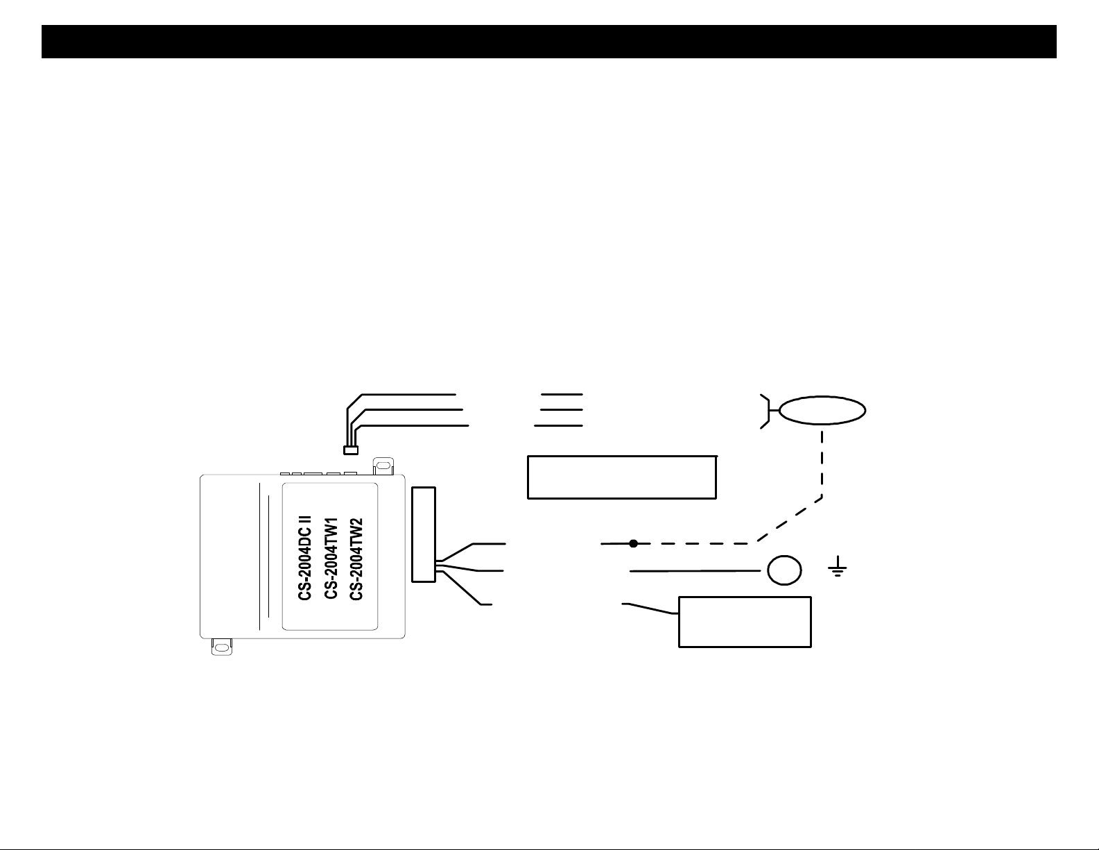
Orange/Black
Brown/Black
Red/Black
(-) Neg. Domelight Illumination
(-) Neg. Auxiliary Channel #1
(-) Neg. Auxiliary Channel #2
Choose One
Gray (Term #85)
White/Red (Term #87)
+12V or
Black/White (Term #30)
Dome light Illumination
Aux. #1, Aux. #2 or
15A Relay Output:
Auxiliary 15A On-Board
relay wiring
INPUT
SOURCE
BROWN/WHITE: (-) HORN HONK OUTPUT (Optional, May require a relay)
Connect to the Negative Horn Trigger wire usually located at or near the steering column. If the vehicle horn circuit
requires +12V, then a relay is required. RELA Y WIRING: Connect the Brown/White wire to terminal 85, connect
relay terminals 86 and 87 to +12V constant power. Connect terminal 30 of the relay to the +12V positive
device/circuit to be activated.
5

WIRING
MINI PLUGS:
2-PIN PLUG (SMALL): LED INDICATOR (RED FLASHING LIGHT)
2-PIN PLUG (LARGE): PROGRAM/OVERRIDE PUSH BUTTON
4-PIN SENSOR PLUG:
RED WIRE: SENSOR +12V POWER
BLACK WIRE: SENSOR GROUND
BLUE WIRE: NEG. W ARN AWAY
WHITE W IRE: NEG. TRIGGER
3-PIN BLUE SENSOR #2 PLUG: (For adding additional
PIN 1: SENSOR +12V POWER single stage sensors)
PIN 2: NEGATIVE (-) TRIGGER
PIN 3: SENSOR GROUND
3-PIN BROWN AUXILIARY/DOME OUTPUT P LUG:
ORANGE/BLACK WIRE: (-) DOME LIGHT ILLUMINATION OUTPUT (Optional)
Provides a Negative Output for 30 seconds upon disarming or until ignition is turned on whichever comes first. Use
this wire for illuminated entry into your vehicle. Connect to the Gray wire if you choose to use the on-board relay, or
this wire can be connected to an external relay [if the on-board auxiliary relay is being used for another function]. If
using on-board relay, see pages 4 & 5, or for external relay see following information:
Negative Dome Light System: Connects to terminal 85 of a relay. Connect terminals 86 +12V Constant.
Connect terminal 87 to Chassis Ground and Connect Terminal 30 to the Negative dome light activation circuit.
Positive Dome Light System : Connects to terminal 85 of a relay. Connect terminals 86 & 87 to +12V fused
Constant. Connect terminal 30 to the Positive dome light activation circuit.
NOTE: Dome light Illumination cancels the active rearm feature.
TIP: The Sensor supplied with
this system does not require
any additional wiring, simply
mount the sensor in a suitable
location, plug in, and adjust to
the desired levels of
sensitivity. The Black dial is
for Pre-warn level and White
dial is for Shock trigger.
6

WIRING
BROWN/BLACK WIRE: (-) AUX. OUTPUT #1 OR M.A.P.-Mobile Accessories Protection (Optional)
This is a programmable output wire that can operate two different ways:
1. (DEFAULT Operation) A Remote Auxiliary Output that provides a ½ Second (-) Negative pulse when Button
#3 is pressed and released to open a power trunk or hatch release. Connect to the Brown/Black wire if you
choose to use the on-board relay, or this wire can be connected to an external relay [if the on-board auxiliary
relay is being used for another function]. If using on-board relay, see pages 4 & 5, or for external relay see
following information: Connect Brown/black to terminal 85 of a relay to operate AUX device or function.
Connect terminal 86 or the relay to +12 Volts constant. Connect terminal 87 to +12Volts or Ground depending
on the type of circuit needed. Use Terminal 30 to activate the AUX function or device.
2. (MAP Operation) Provides a continuous (-) Negative output when the alarm system is put into VALET PARK
MODE. This can be used to interrupt the accessory wire of the vehicle, preventing unauthorized use of the
vehicle’s audio or entertainment systems when VA LET PARK MODE is ON, hence the name “MAP – Mobile
Accessory Protection”.
86 85
87
3087A
START
IGN
ACC
OFF
FM
105.5
wire of mobile accessories such as Audio system
Connect relay as shown to interrupt the power
RADIO, etc.
Brown/Black
MOBILE ACCESSORY PROTECTION
or Video monitors. The Alarm will disconnect
these accessories when in VALET PARK MODE.
CUT
Relay not included
KEY
SIDE
WHITE/RED WIRE: (-) REMOTE OUTPUT #2 (Optional)
This wire provides a momentary (-) Negative auxiliary Output when Button #4 is pressed and held for at least 2
seconds. Connect to the Gray wire if you choose to use the on-board relay, or this wire can be connected to an
external relay [if the on-board auxiliary relay is being used for another function]. If using on-board relay, see pages
4 & 5, or for external relay see following information: Connect this wire to terminal 85 of a relay to operate an AUX
device or function. Connect terminal 86 or the relay to +12 Volts constant. Connect terminal 87 to 12V olts or
Ground depending on the type of circuit needed. Use terminal 30 to activate the AUX function or device. This
output is momentary and will stay active as long as the transmitter button is held down.

POWER DOOR LOCK WIRING
6-PIN DOOR LOCK PLUG 18 GA. (Optional / ON-Board Relays):
VIOLET: DOOR LOCK Relay Term. #87: Normally Open [Polarity Input for Lock relay]
WHITE: DOOR LOCK Relay Term. #30: Common [Lock Output]
GRAY: DOOR LOCK Relay Term. #87A: Normally Closed
VIO/WHT: DOOR UNLOCK Relay Term. #87: Normally Open [Polarity Input for Unlock relay]
GREEN: DOOR UNLOCK Relay Term. #30: Common [Unlock Output]
BLUE: DOOR UNLOCK Relay Term. #87A: Normally Closed
DETERMINING DOOR LOCK TYPE: We recommend determining the type of locking system the vehicle has
before connecting any wires. Incorrect connection may result in damage to the alarm and/or vehicle locking system.
This door lock information is provided as a guide. Your vehicle may differ.
Negative Trigger (-): Many Imports; Late model Ford & General Motors
Negative trigger door lock systems send a Negative (Ground) pulse to existing factory relays to lock and unlock the
vehicle doors.
Positive Trigger (+): Many General Motors; Chr ysler / Dodge / Plymouth
Positive trigger door lock systems send a Positive (+12V) pulse through factory relays to lock and unlock doors.
Reverse Polarity: Many Ford/Lincoln/Mercury/Dodge/Chr ysler/Plymouth and early 90’s GM Trucks
Reverse Polarity systems use no relays, but instead the door lock/unlock motors are controlled directly from the lock
and unlock switches in the door. The lock and unlock wires rest at Negative Ground when not in use. W hen the
lock or unlock button is pressed, one of the circuits is “Lifted” and replaced with +12V causing a lock or unlock.
Single Wire (Dual Voltage): Late model Chrysler/Dodge/Plymouth Vehicles, some 2000-UP GM
Dual Voltage systems have lock/unlock switches that send varying amounts of Positive voltage OR Negative ground
current to the SAME wire for both lock and unlock. W hen the vehicle’s Body Computer Module (BCM) or door lock
module senses different voltages on this wire, the system will either lock or unlock. Single wire door lock systems
require relays and resistors.
Databus Systems (2003 GM Trucks & SUV’s, ‘99-04 Jeep Grand Cherokee)
Databus systems send low current “Data messages” to the door lock controllers in order to lock and unlock the
vehicle. To install aftermarket systems in these vehicles, an interface module is required that converts the regular
lock/unlock pulses into “Data messages” to allow locking & unlocking. Interface modules are sold separately.
8
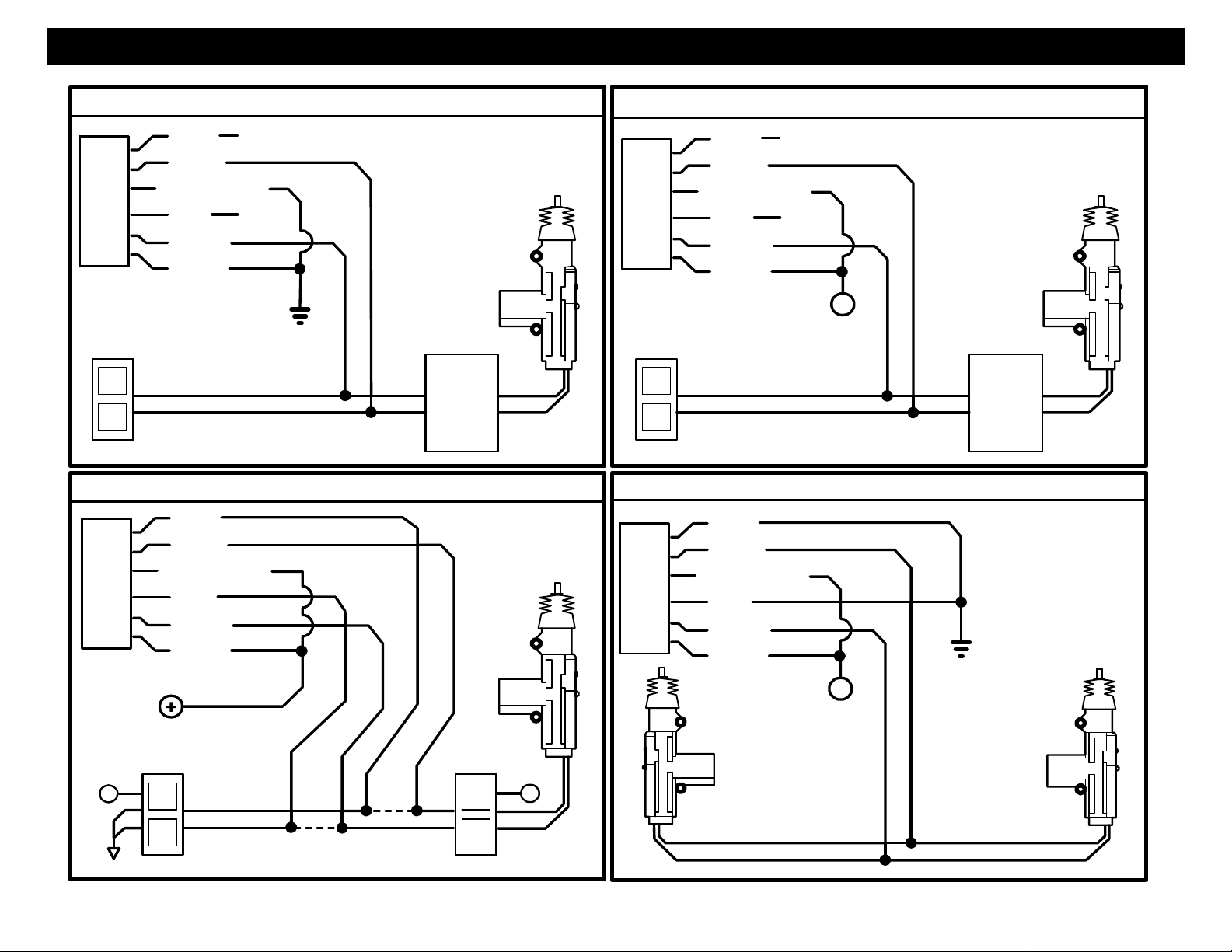
POWER DOOR LOCK DIAGRAMS
UL
REVERSE P OLARITY DOOR LOCK WIRING
+
L
NEGATIVE TRIGGER DOORLOCK WIRING
UL
L
NOT USED
UNLOCK WIRE
CUT
LOCK WIRE
CUT
FACTORY
LOCKING
RELAYS
UL
L
+
AFTERMARKET MOTOR DOOR LOCK WIRING
UL
L
POSITIVE TRIGGER DOORLOC K WIRING
FUSED
+12V
+
UNLOCK WIRE
LOCK WIRE
FACTORY
LOCKING
RELAYS
X =
BLUE
GREEN
GRAY
WHITE
VIOLET
VIOLET/WHITE
X
X
NOT USED
X =
BLUE
GREEN
GRAY
WHITE
VIOLET
VIOLET/WHITE
X
X
FUSED
+12V
BLUE
GREEN
GRAY
WHITE
VIOLET
VIOLET/WHITE
FUSED
+12V
+
BLUE
GREEN
GRAY
WHITE
VIOLET
VIOLET/WHITE
UNLOCK WIRE
LOCK WIRE
9
 Loading...