

CrimeStopper SV-9156CT, SV-9154, SV-9164, SV-9156, SV-9162 User Manual
...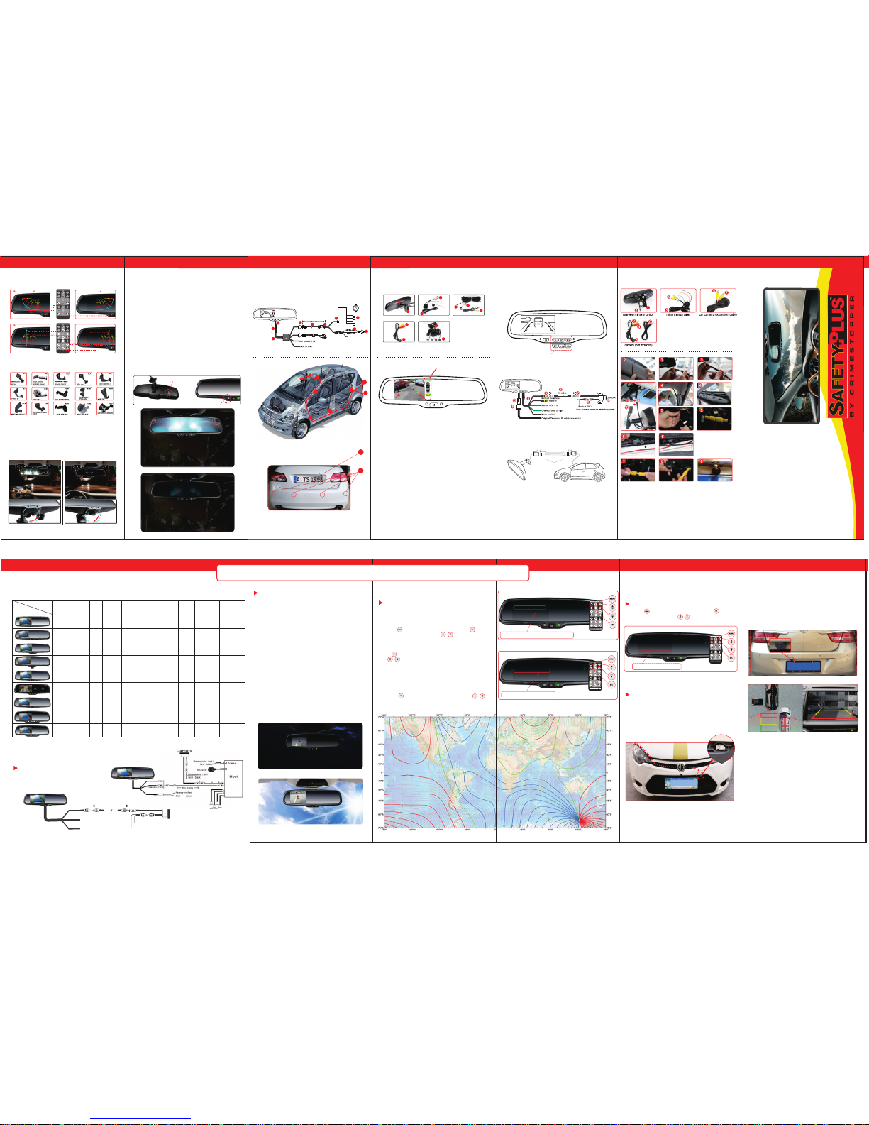
OE-S TYLE D HIGH BR I GHTNES S RE AR VIE W MIR R OR MONITOR
OEM MARKET MOUNT
••• •••••••
••••••••
••••••••••
Check Surrounding for safety
Long press to set guide line
•••••••• ••••
••••••
••• •••••••• •••••
••• •••••••
••••••••
••••••••••
Check Surrounding for safety
Long press to set guide line
•••••••• ••••
••••••
••• •••••••• •••••
Right guid eline ro ta on
Le
guidelin e move Right guid eline m ove
Le gu ideli ne rota on
MANUAL DIMMING
when th e mirro r detect s the hig h beam li ght fro m
the com ing car at t he back , you jus t need to a djust a
switc h so that th e mirro r's ang le has be en chan ged,
which c an avoid t he high b eam lig ht in you r eyes.
Turn off
Turn on
AUTO DIMMING
The auto-dimming of our mirror works automacally
when you start the engine, then the indicator light also
lights. The light sensor in the back of the rearview mirror
will always detect the ambient light. The auto-dimming
doesn't work in the broad day for the adequate daylight.
However, when night falls and the ambient light is below
5lux, the auto-dimming starts to work and automacally
dims to eliminate the glare of rearward-approaching
vehicles. Furthermore, the degree of brightness of the
auto-dimming glass depends on the level of the light.
The stronger the light from the back of the car is, the
darker the glass is. Hence it protects drivers from
becoming dizzy and avoids car accident.
the light sensor from the back of
mirror detects the ambient light
front light sensor detects the light
from rearward-approaching vehicles.
Auto-dimming bleaching state
Auto-dimming working state
PARKING SENSOR
Video in
PUSH OUT
OPEN
ECU
5
3
Rearview mirror monitor
Mirror monitor cable
Extension cable
3
1
Camera
1
3
5
7
11
2
4
6
3
2
4
5
6
7
11
9
10
5
9
8
10
9
10
8
8
11
Parking sensor
Green to back
10
11
Top view di splay st yle
10P
in come from mirror
10Pin 16Pin
16Pin come from your veh
icle
Jumper harness
from your vehicle
USER MANU AL
◆
SV- 9154
SV-9 156
SV-9 157
SV-9 164
SV-9 153
◆◆◆
◆
SV-9 161
◆
SV-9 156CT
◆
Use Backup Camera only (1-1)
Connect Red wire to Reverse Light (+12V),
Black to Ground.
WIR ING OPT IONS
1-1
Black to GND
Red to ACC +12
Back up to camera
5M cable
CAMERA
Black to GND
Red : camera power to reversin g power
1-2
SPEC IFICAT IONS
Red wire to Acc Power and Black wire to Ground.
1.Under power-on condion: when reverse gear is engaged, the system
automacally switches from video sources (such as GPS) to backup
camera video, and when not engaged , it switches back automacally.
Refer to Oponal Wiring Diagram 1-2.
2.Under power-off condion: When reverse gear is engaged, the system
automacally switches to the camera signal and displays backup video.
When not engaged, it switches off automacally.
3.PWR Button on middle of the Mirror
1) Camera mode ( in reverse ), this button is used to adjust the
backlight of the monitor.
2) Video mode, this button is used to turn monitor on/off.
Use Backup camera and Video input (1-2)
SUPER HIGH BRIGHTNESS SCREEN WITH
AUTO ADJUSTMENT
When video from backup camera is displayed on the screen, the screen will
automacally adjust brightness with the ambient light. It can ensure that
you can see the screen clearly under sunshine when the light is super
bright; the screen also can automacally become dimmer, which is enough
to protect you from the sudden light from the turned-on screen at night.
weak light
super bright
ABOUT TEMPERATURE
How to set
ABOUT COMPASS
Digital Compass Calibraon
Temperature sensor installaon
Locate the temperature sensor between the front of the radiator and the
front bumper
Locate edge of sheet metal or plasc shield, and slide metal clip over
edge unl secure.
Sensor should be in the flowing of fresh air. Do not locate it next to a
heated engine part.
12
14
16
18
22
26
24
12
14
16
18
22
24
26
28
34
44
54
66
2
4
6
8
-2
-4
-6
-8
-12
-14
-16
-18
-12
-14
-16
-2
-4
-6
-8
2
4
6
8
12
14
16
18
22
24
26
-2
-4
-6
-8
-12
-14
-16
-16
2
4
6
8
12
14
16
18
• • • • • •
• •••• •• •••••
Brazil
Peru
Chile
Aryentina
• •• •• •• •••• •
• •• •••• •• •
South Africa
Australia
Britain
Franch
Spain
Germany
sweden
印度
los Angel es
A
-18
-22
-24
-26
-28
-32
-34
-36
-38
This compass can be calibrated by driving your vehicle in several
complete circles. A quick guide is stated as below. If the vehicle's
compass headings become inaccurate, the compass can be manually
calibrated by
2. Press to select the “CALIBRATION”, the default mode is “OFF”,
press , select the “AUTO” 2-2
3. Drive your vehicle in at least 2 circles' counterclockwise, allowing 45
seconds to complete one circle
4. For best calibraon, keep your circle radius close to 5 meters and
speed less than 10km.
WHAT TH E REGUL AR GUID E LINE I S
Regular guide line is fixed. But installaon sites of cameras are different
as well as car size. The fixed guide line is not accurate enough for drivers.
There will be a great difference between regular and fixed guide lines and
car's real guide lines, especially when camera is mounted on the le or
right side of car backside. It may cause accidents.
According to the site of standard reference line, we can put reference
objects such as desks in the back area of car. Compared with the marked
reference objects, we can adjust the sites and angle of two guide lines
displayed on the monitor. You will get the accurate and safety guide lines
once they coincide with the reference objects.
Long press setng button is to enter into “guide line adjustment” mode.
The upper half of the remote is to adjust le guide line while the bottom
half of the remote is to adjust the right one. The up, down, le and right
buttons are to adjust the locaon of guide lines. The clockwise rotaon
contra rotaon buttons are to adjust the angle of guide lines. It is easy to
operate and calibrate.
HOW TO ADJUST THE GUIDE LINE
4.3”
TFTLCD
480(H)
×272(V)
Screen
Size
16 : 9 16.7M
8W
DC 12V
VIDEO-IN to GPS
/DVD (default)
CAMERA to
backup camera.
PAL/AUTO/NSTC
Mode number
Color
Depth
Pixel
Pitch (mm)
Power
Consumption
Working
Voltage
Video
Input
Signal System
Display
Screen
Aspect
Resolution
Mode l
Description
SV-915 4
SV-915 6
SV-915 7
SV-915 6CT
SV-915 3
3.5”
4.3”
4.3”
4.3”
TFTLCD
TFTLCD
TFTLCD
TFTLCD
320(H)
×240(V)
480(H)
×272(V)
480(H)
×272(V)
480(H)
×272(V)
4: 3
16 : 9
16 : 9
16 : 9
16.7M
16.7M
16.7M
16.7M
4W
8W
8W
8W
DC 12V
DC 12V
DC 12V
DC 12V
VIDEO-IN to GPS
/DVD (default)
CAMERA to
backup camera.
VIDEO-IN to GPS
/DVD (default)
CAMERA to
backup camera.
VIDEO-IN to GPS
/DVD (default)
CAMERA to
backup camera.
VIDEO-IN to GPS
/DVD (default)
CAMERA to
backup camera.
5. 5. Press to select the “CALIBRATION”, press ,
select the “OFF”
SE T T I N G
CO M PA S S Z O N E
CAL I B R AT IO N
FR O N T S E NS R O
BAC K S EN S O R
TE M P U N I T
00
OF F
01
01
o
F
2-1
COMPASS ZONE 00
1.Pres s the ente r into “S ET TIN G” men u, and pr ess but ton
to choos e the “AN GLE ”. you can pre ss to ad just th e angle . 2-1
(Using t he map be low to fi nd your ge ograp hic loc ation, n ote the z one
that you ar e locat ed)
SE T T I N G
CO M PA SS Z ON E
CAL I B R AT IO N
FR O N T S E NS R O
BAC K S EN S O R
TE M P U N I T
00
AUT O
01
01
o
F
CALI BRATI ON
AUTO
2-2
1.Pres s the ente r into “S ET TIN G”me nu, and p ress but ton to
o
o
choose t he “T EMP UNI T”.pre ss you ca n switc h F to C 3-1
SE T T I N G
ANG L E
CAL I BR AT I O N
FRO NT S EN S R O
BAC K S EN S O R
TE M P U N I T
00
AUT O
01
01
o
F
TEMP UNIT
O
C
3-1
SV-916 1
4.3”
TFTLCD
480(H)
×272(V)
16 : 9 16.7M 8W DC 12V
VIDEO-IN to GPS
/DVD (default)
CAMERA to
backup camera.
SV-916 4
4.3”
TFTLCD
480(H)
×272(V)
16 : 9 16.7M 8W DC 12V
VIDEO-IN to GPS
/DVD (default)
CAMERA to
backup camera.
PAL/AUTO/NSTC
PAL/AUTO/NSTC
PAL/AUTO/NSTC
PAL/AUTO/NSTC
PAL/AUTO/NSTC
PAL/AUTO/NSTC
SV-916 2
SV-916 3
4.3”
4.3”
TFTLCD
TFTLCD
480(H)
×272(V)
480(H)
×272(V)
16 : 9
16 : 9
16.7M
16.7M8W8W
DC 12V
DC 12V
VIDEO-IN to GPS
/DVD (default)
CAMERA to
backup camera.
VIDEO-IN to GPS
/DVD (default)
CAMERA to
backup camera.
PAL/AUTO/NSTC
PAL/AUTO/NSTC
OE-S TYLE D HIGH BR I GHTNES S RE AR VIE W MIR R OR MONITOR
There are two styles of OnStar connectors that are compatible
with the factory rear view mirror. These connectos are a 10-pin
and 16-pin connector. Our OnStar mirror's connector is 10 pins
which will match the original 10-pin OnStar connector. If your
vehicle has the 16-pin connector, we have an adapter that will
convert the 16-pin connector to a 10-pin connector
Note: OnStar and BlueLink systems are the patent and trade
mark of the GM and Hyundai Corporations
Controls for GM OnStar and Hyundai BlueLink systems
GM OnStar and Hyundai Bluelink
Rear View Mirrors
SV-9 162◆SV-9 163
◆
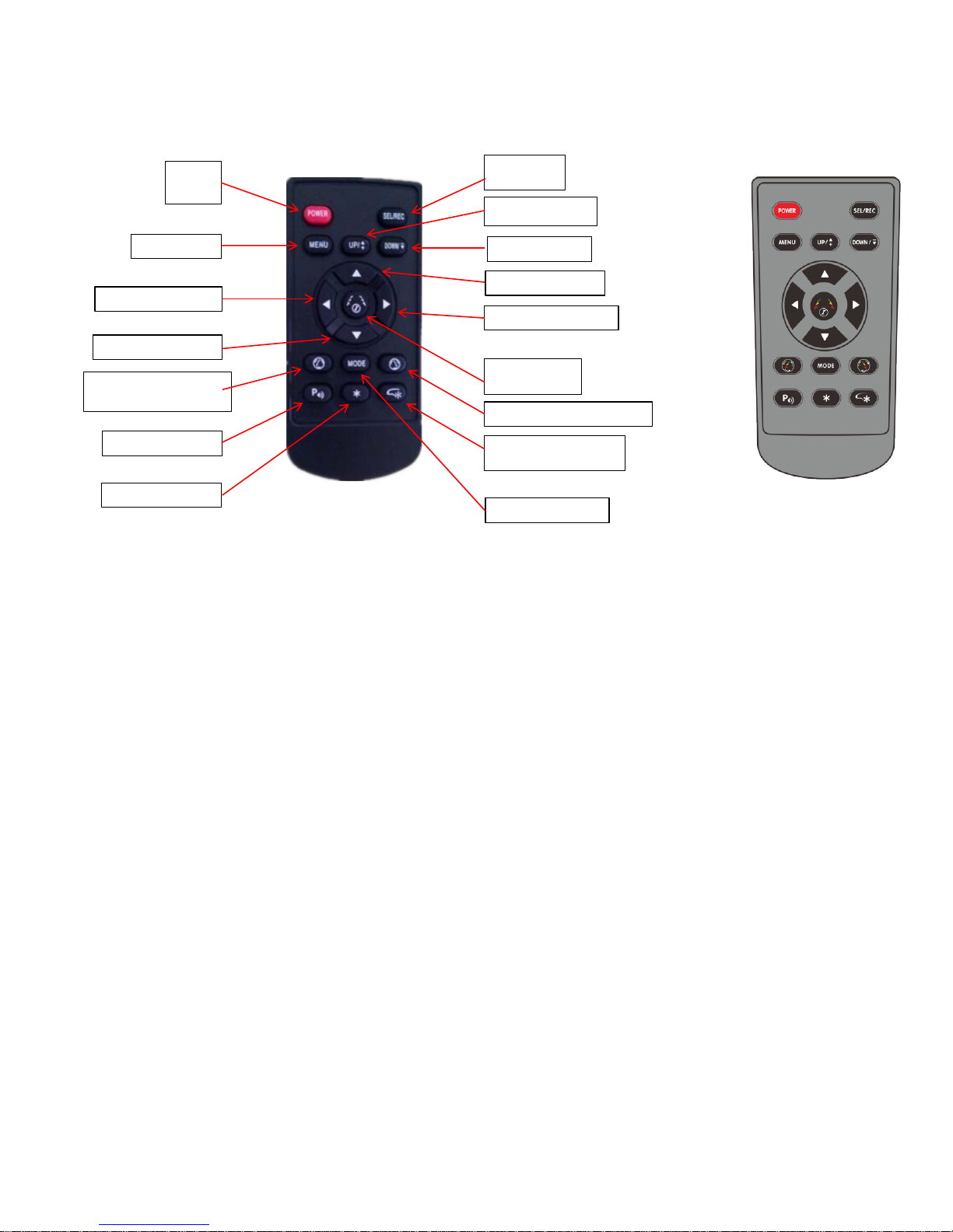
Pls be noted that the remote instruction is not for one single model, but for multi-models.
Power
Menu
selection
Guideline
button
Instruction for New Remote
Increase setting
Menu setting
Guide line moves left
Guideline moves down
Guideline moves
anticlockwise
the ON/OFF for
DVR video switched
Decrease setting
Guideline moves up
Guideline moves right
adjustment
Guideline moves clockwise
on/off for 2.7" AUTO
DIMMING DVR monitor
DVR mode switched
 Loading...