

CrimeStopper SP-302 Operating Instructions Manual

SP-302
2-WAY PAGING ALARM SYSTEM
OPERATING INSTRUCTIONS
INTRODUCTION
CONGRATULATIONS on your choice of a Remote Alarm System by Crimestopper Security Products Inc. This
booklet contains the information necessary for installing, using, and maintaining your alarm system. If any
questions arise, contact your installation dealer or Crimestopper Security Products Inc. at the Tech Support
number below.
*IMPORTANT INFORMATION: Primary and Optional Features:
-PRIMARY: These are features that must be connected in order for the system to operate properly; i.e. the
Siren, L.E.D., +12V Power, Ground, Door pin, Flashing lights Override/Program/Valet Button etc.
-OPTIONAL: These are features to be connected if desired or agreed upon by the installing dealer. These
features may also require additional parts and/or labor fees. Consult with your installer beforehand; i.e. Door
Locks, Starter disable, Hood/Trunk trigger, and Auxiliary Remote Outputs etc.
This installation book is designed for the installer or individual with an existing understanding of automotive
electrical systems, along with the ability to test and connect wires for proper operation. To ease installation, we
suggest that you READ THIS MANUAL before beginning your installation. This book is provided as a GENERAL
GUIDLINE and the information contained herein may differ from your vehicle.
TECH SUPPORT
Mon-Fri 8:00 AM-4:30 PM Pacific Time
(800) 998-6880
REV. 10-2012
This device complies with FCC Rules part 15. Operation is subject to
the following two conditions: 1) This device may not cause interference,
and (2) this device must accept any interference that may be received,
including interference that may cause undesired operation. The
manufacturer is not responsible for any radio or TV interference caused
by unauthorized modification to this equipment. Such modification
could void the user's authority to operate the equipment.

TABLE OF CONTENTS
Operation Cautions & Warnings……..…………..…………………………………………………………….………2
Using The 2-Way Pager…………….....…………..……………………………………………………………….….3-4
Setting the Clock and Beep or Vibrate Selection….…………………………………………………..….....…...4-5
1-Way Sidekick and Battery Replacement…………………………………………………………..………….…...6
Quick Chart Button Functions…..……………..……………….…….………………….…….…………...…………7
.
Operating Instructions………………………..……………….…….………………….…….…………...………...8-11
Alarm Trigger Diagnostics.………………..……………….…….………………….…….…………...………..……12
Car Jack Protection..…………..…………..……………………………………………...…………………..……..…13
Transmitter Programming.………………………………….…………………………….……………...…………....14
2 Vehicle Programming…………..…………..………………….…………………………….…………….……..…..15
Data Port Interface…………………………………………………………………………………………………....…16
OPERATION CAUTIONS & WARNINGS
CRIMESTOPPER SECURITY PRODUCTS, INC. and its VENDORS shall not be liable for any accident
resulting from the use of this equipment. This system is designed to be professionally installed into a car or
vehicle in good running order. Items, such as parking brake, door switches, and all engine safety features,
must be in perfect working condition.
DAMAGE resulting from misuse or negligence is NOT covered under warranty and will be subject to repair
and / or replacement charges.
IT IS ABSOLUTELY THE OWNER’S SOLE RESPONSIBILITY TO: A) Understand the operation of this system
and its safety features. B) Check for proper operation of these safety features prior to accepting delivery of the
vehicle from the installation facility. C) Check and maintain the condition of the vehicle and all items relative to
the proper operation of this system and its safety features.
2
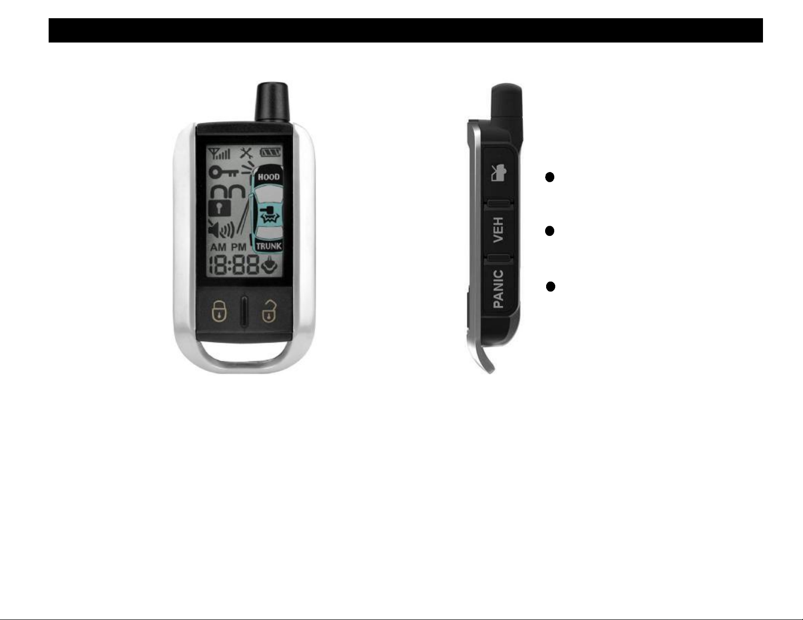
USING THE 2-WAY PAGER TRANSMITTER
AUX Outputs thru Data
Valet Mode
(Tools)
Transmit Signal
Ignition ON
Lock/Unlock
(Arm/Disarm)
Silent no beeps
CLOCK /
Run Count Down
LOCK / ARM
USB Charger
(Under Side Cover)
Note:
Some Icons on the LCD display only function
on the Combo Alarm with Remote Start
POWER OFF FUNCTION
To turn Power ON, press and hold unlock button 2 seconds.
To turn Power OFF, press and hold unlock button 5 seconds.
LCD SCREEN ICONS
Battery Life
Hood Open
Sensor Warning
(Small Hammer)
Sensor Trigger
(Big Hammer)
Door Open
Trunk Open
Remote Started
UNLOCK / DISARM
SIDE BUTTONS
RELEASE
VEHICLE
SELECT
AUX 1 = Trunk + Lock
AUX 2 = Trunk + Unlock
AUX 3 = Panic + Trunk
AUX 4 = Panic + Lock
This remote can control up to 4 AUX
functions thru data depending on the
vehicle and data module. This is typically
used for operating left and right sliding
doors. (Requires Canbus Data Module)
TRUNK
PANIC
3
USING THE 2-WAY PAGER TRANSMITTER
The 2-Way LCD Pager remote transceiver is used to send and receive information from the vehicle. The Control
Module transmits High Frequency FM signals from the vehicle to your pager over long distances. Your range
will vary depending on location, terrain, and local RF noise/interference. This system is not guaranteed to page
you if you are behind concrete walls, underground, in a large structure, or in an area with high levels of
electronic interference. Handle the pager/remote with care. The LCD display and/or the electronics may be
damaged if subjected to abuse.
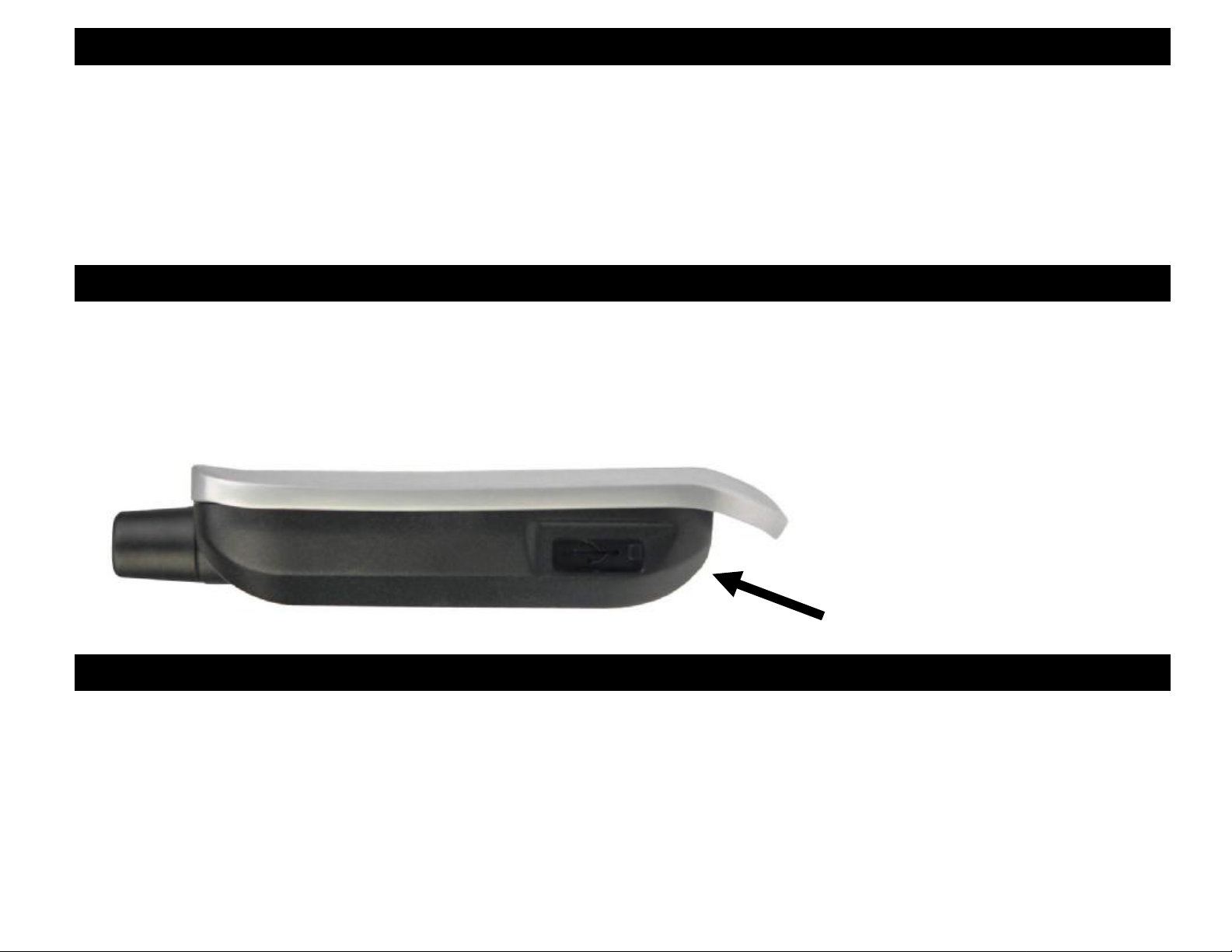
BATTERY CHARGING
The 2-Way LCD remote has a battery charge indicator on top right corner of display. The battery voltage
affects the distance of the remote control. The system comes with a standard Mini USB charging cable
that plugs into the side of remote control. To access to USB plug, slide the cover to the left shown
below.
USB Charging Port
SETTING THE CLOCK (2-WAY- LCD REMOTE)
1. Press VEH Button on the side of the remote control 5 times.
2. The remote will beep and the AM or PM display will begin flashing.
3. Press the Trunk Button to go to the next item – AM - PM - Hour- Minutes.
4. Press the Lock Button to Increase time.
5. Press the Unlock Button to decrease time.
6. Press the PANIC Button to Disable or Enable Beep and Vibration. See next page.
7. Press the VEH Button to Save and Exit Setup or wait 8 seconds, the LCD light will turn off.
4
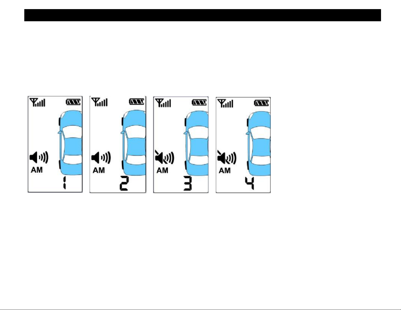
REMOTE BEEP & VIBRATE SELECTION
The LCD pager remote BEEPS and VIBRATES when it receives a signal from the vehicle. The Beeps and
Vibration are selectable (on/off). To enter program mode,
1. Press VEH Button on the side of the remote control 5 times.
2. The remote will beep and the AM or PM display will begin flashing.
3. Press the Panic button to choose the mode of “Beep ON/OFF & Vibrate ON/OFF”.
4. Press the VEH Button to Save and Exit Setup or wait 8 seconds, the LCD light will turn off.
Mode 1: The remote beeps once and vibrates: this indicates “Beep ON & Vibrate ON”.
Mode 2: The remote beeps once without vibration; this indicates “Beep ON & Vibrate OFF”.
Mode 3: The remote only vibrates, without beep; this indicates “Beep OFF & Vibrate ON”.
Mode 4: The remote does not vibrate or beep; this indicates “Beep OFF & Vibrate OFF”.
5
 Loading...