

Crimestopper RS-900 Installation Manual

RS900ER/RS901
SERIES I
REMOTE ENGINE STARTING SYSTEM
INSTALLATION INSTRUCTIONS
This Remote Start Module provides the following features:
SELECTABLE ENGINE SPEED SENSING: TWO PROGRAMMABLE MULTI-
• Tach, Semi-Tachless, & Vacuum FUNCTION OUTPUTS FOR:
• OEM Alarm Disarm
TACH AMPLIFIER: • Throttle Pulse for Carbureted vehicles
• For dirty or low-level tach signals • Starter Disable / Anti-Grind Output
• Remote output for trunk pop
PROGRAMMABLE RUN TIME: • Host alarm sensor disable
• 10, 20, or 40 minutes • Defroster Activation
4 ON-BOARD RELAYS: HOOD / BRAKE SAFETY CIRCUITRY
• Main Ignition (IGN1)
• IGN2 / Accessory VALET MODE / OVERRIDE
• Starter
• Parking Light OEM ALARM / KEYLESS ACTIVATION:
• Lets a Factory Keyless Entry or Alarm
REMOTE KEYLESS ENTRY: AUX output activate the Remote Start
• Controls power door locks
DIESEL START COMPATIBILITY
SECURITY STARTER DISABLE
DELAYED REMOTE CONTROL
TIMED SELF-START MODE: OPERATION:
• Program vehicle to start every • Prevents accidental Remote Starts
1-4 Hours
CODE / TACH LEARNING CIRCUITRY
Some of the features listed above are optional connections, and may require additional parts and labor.
TECHNICAL SUPPORT: 1-800-998-6880
Monday - Friday 8:00am - 4:30pm Pacific Time
Web Site: www.crimestopper.com
E-mail: tech-support@crimestopper.com
CRIMESTOPPER SECURITY PRODUCTS, INC.
1770 S. TAPO STREET, SIMI VALLEY, CA. 93063
This device complies with FCC Rules part 15. Operation is subject to the following two conditions:
(1) This device may not cause harmful interference, and (2) This device must accept any
interference that may be received, including interference that may cause undesired operation. The
manufacturer is not responsible for any radio or TV interference caused by unauthorized
modifications to this equipment. Such modification could void the user’s authority to use the
equipment.

INSTALLATION CONSIDERATIONS / WARNINGS
To ease and reduce installation time, we suggest you consider the following points before starting.
1. Determine most suitable locations for all components to be placed. These components include: the
module itself, override / programming switches, and possible relays.
2. Use a Volt-Ohm meter to test and locate all connections.
3. Record all color codes of vehicle wiring to be used for reference. This will save time by not having to
re-test the same wires over again.
4. Allow enough wire to create a service loop with strain relief, should servicing be required. This will
also allow easier access and mounting.
**FOR SAFETY REASONS, DO NOT INSTALL RS900/901 in vehicles with MANUAL
TRANSMISSIONS.** If accidentally left in gear, a remote started vehicle could become a self-propelled
threat to life and property.
DO NOT extend the RS-900 Remote start ignition harness length. Mount the module so that main
harness reaches all ignition switch wiring. Extending these wires could result in poor performance.
DO NOT route any wiring that may become entangled with brake, and gas pedals, steering column, or
any other moving parts in the vehicle.
DO NOT exceed the rated output current of any circuit on the Remote start module. Failure to observe
this warning will result in damage to the unit.
DO NOT remote start the vehicle in a closed garage. Make sure that the garage door is open or there is
adequate ventilation. Failure to observe this rule could result in injury or death from poisonous Carbon
Monoxide fumes.
Warning: This system DOES NOT HAVE engine over-rev protection. Make certain
vehicle throttle linkage operates properly and does not stick. A stuck throttle will
cause severe engine damage
WIRING INSTRUCTIONS
PROGRAM/OVERRIDE SWITCH: 2 PIN PLUG
This switch is used primarily for programming features of the RS900/901. However, if the Anti-Grind/Starter disable
feature is installed, you MUST INSTALL this switch. This switch will allow the user to override the starter disable in
the event of a non-operating remote control.
8 PIN PLUG:
PIN 1: TAN: MULTI-FUNCTION OUTPUT 1
This output comes pre-programmed to provide a ground pulse to disarm the vehicles' FACTORY anti-theft system
prior to ignition on and 2 seconds after start for Defroster activation. This output can also be changed to operate as
a Remote controlled output for trunk release. See Programming Section.
For OEM Disarm: Connect this wire to the vehicles' anti-theft disarm wire. This wire is usually found coming off the
Driver's door keyswitch or the Factory Anti-theft control module.
For Defroster Activation: Connect this wire to the vehicle's defroster activation switch. It may be necessary to use
a relay. If using both OEM Disarm and Defrost Activation, Use relays to isolate the two circuits from operating
simultaneously, or use diodes to isolate interference.
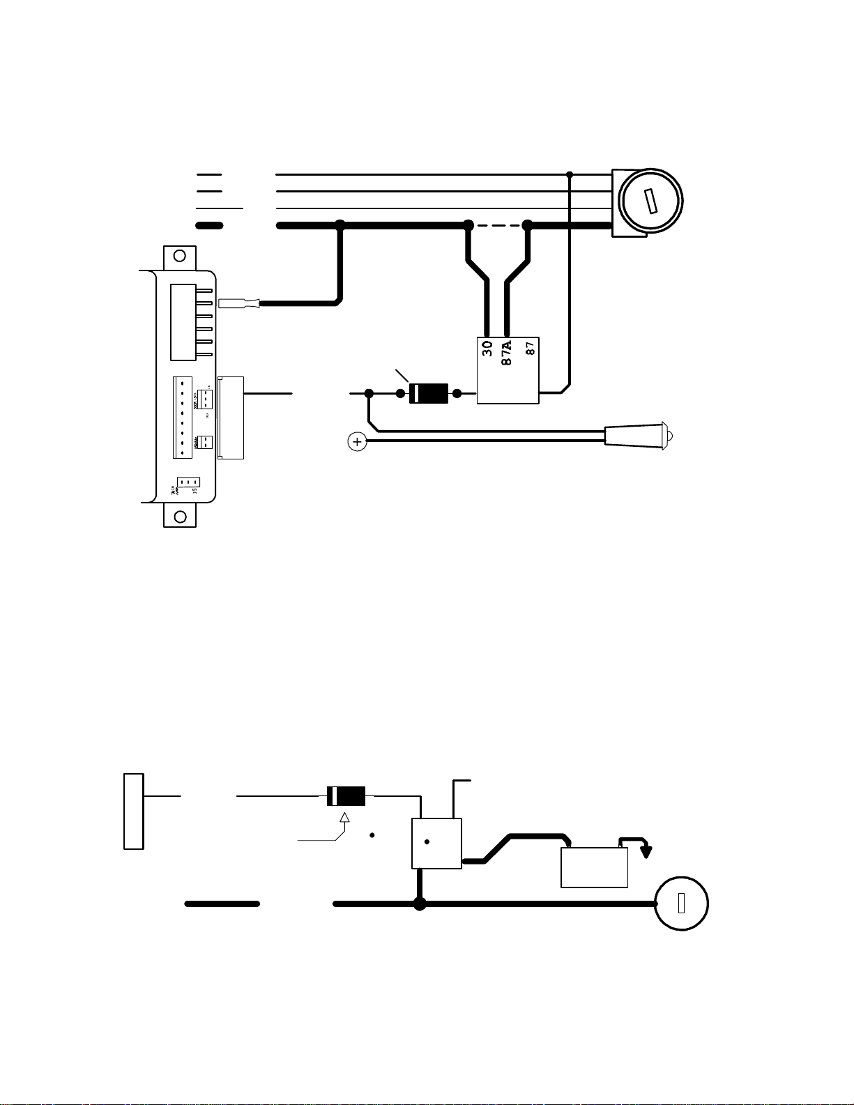
PIN 2: ORANGE: MULTI-FUNCTION OUTPUT 2
Output 2 comes pre-programmed to operate as the Anti-Grind/Starter Disable output. It can also be used for the
sensor disable circuit for a host alarm. This output activates whenever a remote start is requested, and when the
vehicle is remotely locked with the transmitter. Connect this wire to terminal 85 of a relay. See diagram below.
TO
MOTOR
IGN 1
IGN 2
ACC
START
BROWN
OPTIONAL
RELAY
OPTIONAL 1N4001 DIODE
USE WITH LED ONLY
ORANGE
MAKE CERTAIN TO CONNECT "BROWN" START OUTPUT WIRE TO
MOTOR SIDE OF ANTI-GRIND/START DISABLE RELAY.
CUT
OPTIONAL LED
RECOMMENDED
8685
FOR VEHICLES
WITHOUT DOORLOCKS
PIN 3: BLACK: MAIN SYSTEM GROUND
Connect to chassis metal of the vehicle. An existing bolt or screw MAY provide an adequate ground, or drill a small
hole, scrape away paint and attach using a sheet metal screw & star washer. If this wire is not connected OR
connected to a point on the vehicle that provides a poor ground, undesirable and inconsistent operation will occur.
This is a mandatory connection.
PIN 4: YELLOW: IGNITION 1
NEGATIVE (-) OUTPUT FOR RELAY
Use this wire when the vehicle requires a second IGNITION1, IGNITION2, or ACCESSORY wire to be activated.
This occurs commonly in Toyota, and late model GM cars. See diagram below:
YELLOW
INSERT DIODE AS SHOWN
WHEN CONNECTING FOR "IGN 2"
2nd IGN 1
OR
2nd IGN 2
85
86
30 87
CONNECT TO "GRAY IGN 2" WIRE
WHEN WIRING RELAY FOR IGN 2
OR
CONNECT TO BATTERY FOR IGN 1
+
BATTERY
-
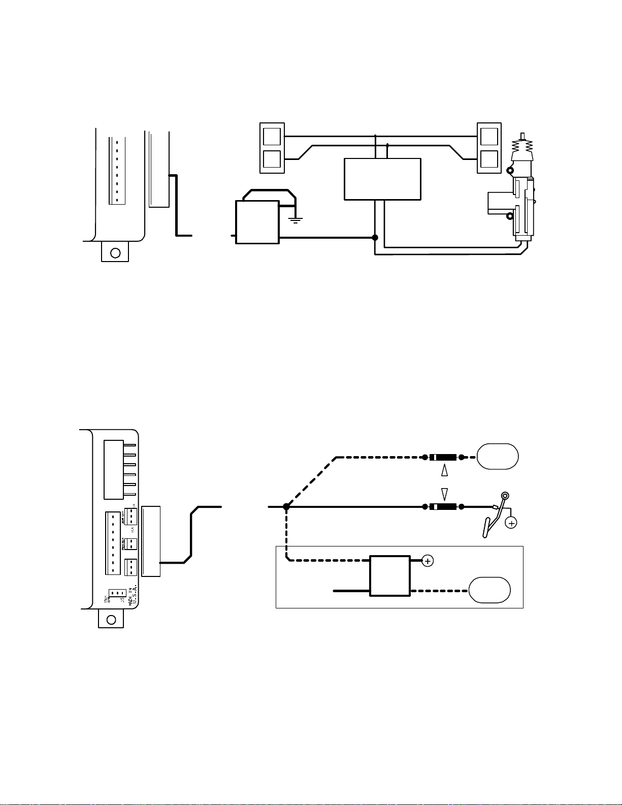
PIN 5: GREEN: (-) START ACTIVATION TRIGGER
This wire allows a host alarm (-) Negative Auxiliary Channel Output to activate a Remote Start or it can be
connected to a Negative wire of a factory keyless entry system. If the Factory Keyless Entry System wire can
produce a Negative output for 1 second or 3 short pulses within 5 seconds, that system could also be used to trigger
a remote start. See diagram below for Factory Keyless interface.
GREEN
85
L
FACTORY
LOCK
RELAYS
87
8630
L
ULUL
+12V LOCK WIRE
PIN 6: GRAY: - HOOD SWITCH
Connect this wire to a switch that is at ground when the hood is open. If an existing switch is not available, then one
must be installed. When this wire is grounded, the remote start is inhibited. This is a mandatory connection!
PIN 7: PURPLE: + BRAKE RESET
Connect PURPLE wire to the side of brake pedal switch that shows +12 volts ONLY when pedal is depressed. This
will turn off the remote start if someone attempts to drive the car without the keys or if the Ignition key is not turned
on all the way. Brake pedal must be pressed for at least 1 second before reset will occur.
DIESEL
WAIT TO START
1N4005
LAMP
WAIT
INSERT DIODES WHEN USING BOTH
PURPLE
30
+IGN
NEGATIVE "WAIT-TO-START" WIRING
85 86
87
1N4005
(-) DIESEL
WAIT TO START
LAMP
WAIT
PIN 8: RED/WHITE: (+/-) TACHOMETER/VACUUM SENSE
This wire MUST BE CONNECTED to the vehicle to sense the engine running. This is so the control module can
control the starter motor to determine when to disengage the starter and to prevent the starter from engaging when
the engine is running.
This system has three methods of sensing an engine running condition:
• True Tach Learning: This is the best and most reliable method.
• Semi-Tachless/Timed Starting: An alternative for vehicles with hard to locate tach sources.
• Vacuum Sensing: When all else fails.

TACH LEARING MODE
The TACH LEARNING MODE is the most reliable and consistent method of engine speed sensing. This wire looks
for the pulsing signal that is created to monitor the engine speed or fire the coil. Most modern ignition systems utilize
a crankshaft sensor to monitor the engine speed. There are 4 different types of signals that may provide adequate
signal for TACH SENSE:
Type 1 - Will be a computer-controlled ignition. On these systems the engine speed reference (tach) may come
from several possible locations. The wire may be found at: Distributor, Ignition Module, Coil Pack, Engine
Computer, or Crankshaft Sensor. THIS WILL BE THE MOST RELIABLE AND CONSISTENT SIGNAL.
Type 2 - Will be a standard ignition coil. Connect the RED/WHITE 22-gauge wire to the negative(-) side of coil.
Note: The coil MAY NOT BE A GOOD LOCATION FOR TACH SOURCE. The coil wire may be too noisy for the
system to detect a clean signal and/or the vehicle uses a Multi-spark ignition system that varies the spark.
Type 3 - Will be computer controlled fuel injection solenoids. This wire can be found at the Injectors in the
engine compartment or at the engine computer.
Type 4 - Will be the Alternator Stator pin on the alternator. This is found on many GM and Ford Diesel trucks
from the mid 1980's through the mid 1990's.
Use the Tach Finder Mode below to locate your tach source wire.
TACH-FINDER MODE
TACH-FINDER MODE is a unique feature to help installers easily identify wires which may be POSSIBLE sources
for an engine speed reference by using the same RED/WHITE wire to probe ANY wiring, WITHOUT RISK TO THE
COMPUTER SYSTEMS.
Tach-Finder may be operated by following the procedure below:
1) OPEN HOOD (ground GRAY hood switch wire) and Start engine.
2) Depress and Hold the BRAKE PEDAL and THEN PRESS THE PROGRAM BUTTON until the parking lights
come on solid.
3) Connect the RED/WHITE tach wire to a scribe or sharp probe. It may be necessary to extend RED/WHITE wire.
Probe the wires that may provide the proper signal. Warning: be certain to protect yourself from electrical
shock!!
4) Start probing wires, When a wire with a pulsing signal is probed, the parking lights will start FLASHING.
5) At this time, turn engine/ignition off. Parking lights will stay ON.
6) Verify tach signal. Turn Ignition ON but DO NOT START ENGINE and probe the same wire.
A) If parking lights start FLASHING, you have found a DATA wire. This wire will tell the system the engine is
running even if it the engine is not running. RESTART ENGINE and Repeat steps 4-6 with another wire.
B) If parking lights stay SOLID then START ENGINE. If park lights stay on SOLID after engine is started,
there is no tach source. Repeat steps 4 through 6 to locate another wire. If park lights start FLASHING
after engine is started, the tach source may be valid.
7) Turn engine OFF, park lights will remain ON. Permanently connect RED/WHITE wire to the located tach lead.
8) Now it is time to PROGRAM the TACH REFERENCE:
A) Start engine (with hood open), parking lights should start flashing.
B) Depress and hold BRAKE PEDAL down.
C) Press and hold PROGRAM SWITCH for 2 seconds. Parking lights will stop flashing while button is
depressed.
D) Turn Ignition OFF, close hood. Parking Lights will still be ON. Tach Programming is now complete.
E) Depress BRAKE PEDAL to clear parking lights.
 Loading...