

CrimeStopper LC-1, LC-3, LC-4, LC-7 Installation Instructions Manual

LC-1 / LC-3 / LC-4 / LC-7
This device complies with FCC Rules part 15. Operation is subject to
the following two conditions: (1) This device may not cause harmful
interference that
may be received, including interference that may cause undesired
operation. The manufacturer is not responsible for any radio or TV
interference caused by unauthorized modifications to this equipment.
ser’s authority to use the
LC-00 (ADD-ON MODULE)
LOW CURRENT
REMOTE START SYSTEM
INSTALLATION INSTRUCTIONS
CONGRATULATIONS on your choice of a “Cool Start” System with Data Port Technology for direct connection to bypass
module by Crimestopper Security Products Inc. This booklet contains the information necessary for installing your remote
starter system. If any questions arise, contact your installation dealer or Crimestopper Security Products Inc. at the Tech
Support number below.
Note: Some features will not be available on units with 1 button, 3 button, and 4 button remotes.
DISCLAIMER:
This installation book is designed for the installer or individual with an existing understanding of automotive electrical
systems, along with the ability to test and connect wires for proper operation. To ease installation, we suggest that you
READ THIS MANUAL before beginning your installation. This book is provided as a GENERAL GUIDELINE and the
information contained herein may differ from your vehicle. Crimestopper Security Products, Inc. and its’ vendors shall not
be liable for any accident resulting from the use of this product. This system is designed to be professionally installed into
a vehicle in which all systems and associated components are in perfect working condition.
TECHNICAL SUPPORT: (800) 998-6880
Monday - Friday 8:00am - 4:30pm Pacific Std. Time
Web Site: www.crimestopper.com
E-mail: tech-support@crimestopper.com
CRIMESTOPPER SECURITY PRODUCTS, INC.
1770 S. TAPO STREET, SIMI VALLEY, CA. 93063
interference, and (2) This device must accept any
Such modification could void the u
REV A 07-2014

TABLE OF CONTENTS
Pre-Installation Considerations….………...……...………………………………………………………………..….………..2
Installation Cautions & Warnings………………………………………………………………………………..….....……..…3
6 Pin Power Plug Wiring………………………………………..………………………………………………………………..3
Parking Light Wiring…………………..………………………………………………………………..………………………...4
12 Pin Low Current Plug Wiring……….………….………………………………...…………………….….……..………..5-7
Power Door Lock Wiring...…………………………………….…………….……..…………...….…………..…..………....8-9
Smart Tachless and Tach Finder Mode………………………………….…………………..…..…….…......……….…10-11
Tach Programming……..…..…….…………………………………………………………………………....….…...............12
Diesel Glow Plug Delay..………………….……………………………...……………………...…..…………..…….………13
Option Programming Table………. …….………….……………………………..……………..…….....….….....……..13-15
Option Descriptions……………..……………………………...………….……….……..…………………………..……16-20
Antenna Diagram……………………….…………………………………………………………..………………………..….20
Transmitter Programming / 2 Vehicle Programming………………………….….…………..………...…..…..……..........21
Manual Transmission Mode……………………….………………………………...…………………….….……..…………22
Wiring Diagram…………………………..…………………………..………………………………..………..….……….…..23
Remote Start Diagnostics.…………….…………………………………………………………..………………………..…..24
Data Port………..……………………….…………………………………………………………..………………………..….24
PRE-INSTALLATION CONSIDERATIONS
BEFORE BEGINNING, check all vehicle manufacturer cautions and warnings regarding electrical service (AIR BAGS, ABS
BRAKES, ENGINE / BODY COMPUTER AND BATTERY).
PLAN OUT YOUR INSTALLATION and determine most suitable locations for all components to be placed. These components
include: the module itself, valet/program button, possible relays, and antenna/receiver (LC-1, LC-3, LC-4 and LC-7 only, the LC00 model does not include antenna or remotes.) Allow enough wire to create a service loop with strain relief, should servicing be
required. This will also allow easier access and mounting.
DAMAGE to the CoolStart unit resulting from incorrect installation or failure to follow guidelines stated in this book will not be
covered under warranty and will be subject to repair or replacement charges.
USE A VOLT OHM METER to test and locate all connections. Test Lights can damage a vehicle’s computer systems.
ADDITIONAL PARTS, which are not included with this unit, may be needed for your particular vehicle. These items may include
extra relays or Anti-Theft System Bypass modules.
2

INSTALLATION CAUTIONS & WARNINGS
DO NOT extend the Remote start ignition harness length. Mount the module so that main harness reaches all ignition
switch wiring. Extending these wires could result in poor or improper performance.
DO NOT route any wiring that may become entangled with brake, gas pedals, steering column or any other moving parts
in the vehicle.
DO NOT exceed the rated output current of any circuit on the Remote start module. Failure to observe this warning will
result in damage to the unit not covered under warranty.
DO NOT remote start the vehicle in a closed garage! Make sure that the garage door is open or there is adequate
ventilation. Failure to observe this rule could result in injury or death from poisonous Carbon Monoxide fumes.
WIRING 6 Pin Power Plug
RED: 12 Volt Power Source 10 Amp
Connect to a constant power source at battery or fuse box when powering the Pink and Pink/white wire. The ignition
switch on many new vehicles have only a 2 or 3 amp power wire so this can not be used. Not necessary to connect
when using a Data Module with a “T” harness plug. The data plug can supply 1 amp to operate the electronics.
BLACK: MAIN SYSTEM GROUND
Connect to chassis metal of the vehicle. An existing bolt or screw may provide an adequate ground, or drill a small hole,
scrape away paint and attach using a sheet metal screw & star washer. This wire must be connected to a proper ground
or undesirable and inconsistent operation will occur. Do not use Factory ground locations.
PINK/WHITE: Programmable Option #4
This is an optional multi-function output wire the can be configured as a Second IGN, ACC or STARTER output. Use
Option #4 to select ACC, IGN or STARTER. The DEFAULT setting is IGNITION.
PINK: Ignition Input/Output 10 Amp Max
This is the ignition source for programming system. This also supplies 12 volts out during Ignition and Start for remote
starting vehicle. Some data modules supply this function so may not be necessary to connect. Consult installation
guide of data module
3
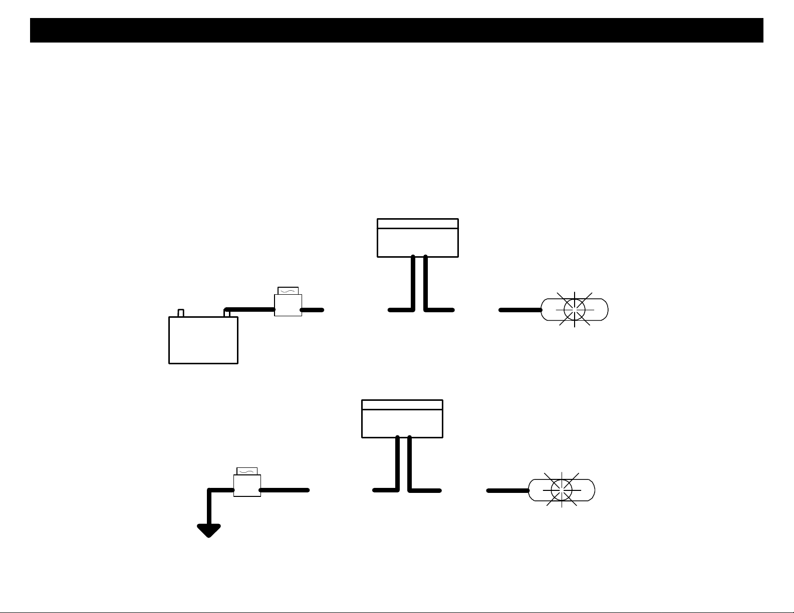
WIRING – Parking Lights
The Parking Light circuit can be connected up as a high current positive or negative trigger. Connect to vehicle
parking light circuit at the back of light switch or if this is not possible, connect directly to one of the parking lights at
the front of the vehicle. If your vehicle has a multiplex lighting system, that will require a resistor connected in series
with the white wire to the light switch. Use the Negative parking light circuit for Multiplex resistor lights.
RED/BLACK: INPUT SOURCE (12 Volts or Ground) 10 Amps Maximum
WHITE: PARKING LIGHT OUTPUT
Positive Parking Lights
(+) Parking Lights
(+)
12 Volt
Battery
10 AMP
FUSE
Red/black
(Lights)
White
Negative Parking Lights
(-) Parking Lights
10 AMP
FUSE
Ground
Red/black
(Lights)
White
4
WIRING Low Current 12 Pin Plug
YELLOW BLACK OUTPUT: Ground Out when Running (-) 500 milliamp
The Ground Out when Running is required by some bypass modules. This wire turns on when the remote start button is
pressed and stays on through the duration of the remote start.
BROWN: (-) AUX OUTPUT (Trunk POP or Dome Light Illumination)
This output is programmable for 2 modes of operation. See Programming Option #9 Section.
1. 30 second Dome Light output.
2. Momentary ½ second output (Default).
Note: Some vehicles like Lexus and Toyota require a 2 to 3 second output for the Trunk Pop to operate.
Option 6-3 (Push and Hold), Allows output to stay on until Transmitter button is released.
TRUNK OUTPUT or DOME LIGHT
+12V CONSTANT
Brown
85
86
30 87
+12V CONSTANT
Trunk Soleniod
OR *
(Default)
-OR-
Dome Light
Circuit
5
* Test activation circuit in vehicle.
Connect to+12V for Positive circuits
or Ground for Negative circuits. Relay
not included.

GRAY: (-) NEGATIVE HOOD PIN SWITCH
Connect the Gray wire to a switch that is at ground when the hood is open. If an existing switch is not available, then we
recommend one to be installed. When this wire is grounded, the remote start is inhibited. The unit will not attempt to start
if hood is open.
ORANGE / WHITE (-) ACC, IGN or AUX 2 OUTPUT (Programmable option 24)
This output is selectable (-) Accessory, (-) Ignition or (-) AUX 2. Default = (-) ACC
BLUE/ORANGE (-) STARTER OUTPUT: Some vehicle require a (-) Start Activation for “Push to Start”.
ORANGE BLACK: (-) OEM DISARM OUTPUT
This wire provides a Ground pulse to disarm the vehicles' Factory anti-theft system prior to a Remote Start. Connect this
wire to the vehicles' anti-theft disarm wire. This wire is sometimes found coming off the Driver's door key switch or at the
Factory Anti-theft control module. This wire may not be needed if Factory Security only requires a door unlock pulse.
ORANGE: (-) OEM REARM OUTPUT or AUX 2 Output (programmable option 25)
This wire is programmable as OEM Rearm or 2nd Aux output. This wire provides a ground pulse to rearm the vehicles'
FACTORY anti-theft system after a timed-out or aborted remote start. Connect this wire to the vehicles' anti-theft rearm
wire or to the door pin circuit depending on your requirements. This wire may be needed to pulse the door pin circuit on
vehicles with retained accessory power.
YELLOW: (-) HORN CHIRP HONK OUTPUT (Programmable 15, 20 or 40 milliseconds, Option 16)
Connect to the LOW CURRENT Negative Horn Trigger wire usually located near the steering column. If the vehicle horn
circuit requires 12V, then a relay is required. RELAY WIRING: Connect the Yellow wire to terminal #85, connect relay
terminals #86 and #87 to 12V constant power. Connect terminal #30 to the 12V positive Horn activation wire.
PINK: NEGATIVE GLOW PLUG (Programmable for fixed time delay, Option 19)
Connect Pink wire to indicator circuit that shows a (-) Signal while the WAIT TO START LAMP is on. When this wire is
used, the system will wait until light turns off before attempting a remote start.
Note: Used for Manual Transmission Door Trigger Input, Option 11
WIRING Low Current 12 Pin Plug
6
WIRING Low Current 12 Pin Plug
RED WHITE: TACHOMETER INPUT
When installing the system in Tach mode, this wire must be connected to a valid source of AC voltage. This wire allows
the unit to sense the engine running and control the starter motor.
PURPLE: (12V) BRAKE RESET
Connect the Purple wire to the side of brake pedal switch that shows 12 volts ONLY when pedal is depressed. This is the
wire that turns off the remote start once the driver’s key is in the Ignition and turned to the ON position.
GREEN (-) START ACTIVATION INPUT or OEM INTERFACE (3 Pulse Start)
Option 17-1 OEM Interface (3 Pulse Start):
This mode allows the system to Remote Start or Stop with 3 successive Lock pulses. There are 2 Modes of operation.
1. Remote Start thru data (green wire not connected). This feature only works on newer CANBUS vehicle using a
Data Module that supports this feature. With this option you can use both the OEM and Crimestopper remote.
2. Connect the Green input wire to the Negative lock signal wire of the factory system. If your Factory OEM system
Option 17-2 Default (-) Neg. Start Activation:
This wire allows an alarm or keyless entry system with a remote Aux channel to activate the Remote Start by sending a
(-) momentary pulse to the Green input wire. This triggers a remote engine start or stop
does not have this type of signal, then a relay is required.
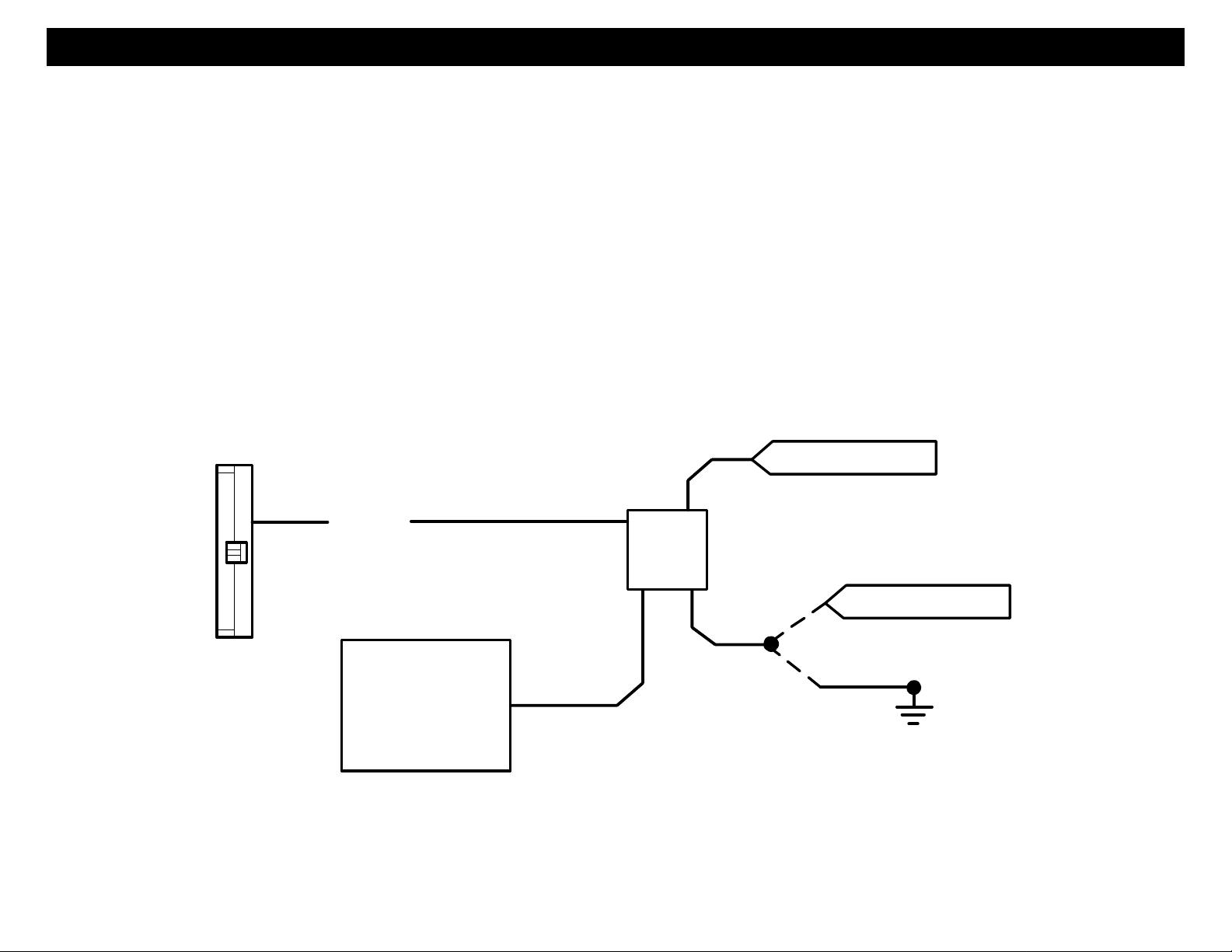
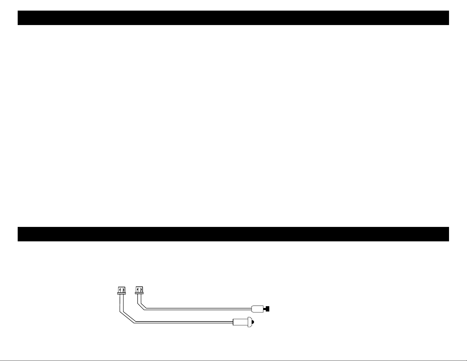
WIRING LED and Valet Switch
PROGRAM OVERRIDE SWITCH: 2 PIN PLUG (REQUIRED FOR PROGRAMMING & LEARNING REMOTES)
This is a multi-function switch used for programming options, transmitters, valet mode.
LED: 2 PIN PLUG
The LED is used for Remote Start Diagnostics and a Valet indicator. It will also Flash for use as security deterrent.
VALET / PROGRAM SWITCH
STATUS LED
7

POWER DOOR LOCK WIRING CONNECTOR
BLUE: (-) Negative pulse for UNLOCK
RED: 12V When using external relays (TERM 86)
GREEN: (-) Negative pulse for LOCK
DETERMINING DOOR LOCK TYPE: We recommend
determining the type of locking system the vehicle has before
connecting any wires. Incorrect connection may result in
damage to the alarm and/or vehicle locking system. Door lock
information is provided as a guide. Your vehicle may differ.
Negative Trigger (-): Many Imports; Late model Ford & General Motors
Negative trigger door lock systems send a Negative (Ground) pulse to existing factory relays to lock and unlock the
vehicle doors.
Positive Trigger (+): Many General Motors; Chrysler / Dodge / Plymouth
Positive trigger door lock systems send a Positive (12V) pulse to existing factory relays to lock and unlock the vehicle
doors.
Reverse Polarity: Many Ford/Lincoln/Mercury/Dodge/Chrysler/Plymouth and early 90’s GM Trucks
Reverse Polarity systems use no relays, but instead the door lock/unlock motors are controlled directly from the lock
and unlock switches in the door. The lock and unlock wires rest at Negative Ground when not in use. When the lock
or unlock button is pressed, one of the circuits is “Lifted” and replaced with +12V causing a lock or unlock to occur.
Single Wire (Dual Voltage): Late model Chrysler/Dodge/Plymouth Vehicles, some 2000 GM
Dual Voltage systems have lock/unlock switches that send varying levels of Positive voltage OR Negative ground
current to the SAME wire for both lock and unlock. When the vehicle’s Body Computer Module (BCM) or door lock
module senses different voltages on this wire, the system will either lock or unlock. Single wire door lock systems
require relays and resistors.
Databus and Canbus Systems (Data Module Required)
Databus systems send low current “Data messages” to the door lock controllers on a network in order to lock and unlock
the vehicle. To install aftermarket systems in these vehicles, an interface module is required that converts the regular
lock/unlock pulses into “Data messages” to allow locking & unlocking. Interface modules are sold separately.
Crimestopper Door Lock Accessories:
CS-6600DLM: Dual-relay plug-in module for Reverse
Polarity, Positive, or Aftermarket Motors.
CS-6500DLI: Plug-in pulse inverter that converts the
Negative outputs of the system to Positive type for Positive
Door Lock systems.
CS-610S1: Aftermarket door lock actuator (motor).
8
 Loading...