

CrimeStopper CS-845RKE Installation & Operating Instructions Manual

REMOTE KEYLESS ENTRY SYSTEMS
INSTALLATION & OPERATING INSTRUCTIONS
CS-845RKE / CS-855RKE
INTRODUCTION
CONGRATULATIONS on your choice of a Remote Keyless Entry System by Crimestopper Security Products
Inc. This booklet contains the information necessary for installing, and using your system. If any questions
arise, contact your installation dealer or Crimestopper Security Products Inc. at the Tech Support number
below.
*IMPORTANT INFORMATION: Primary and Optional Features
-PRIMARY: These are features that must be connected in order for t he system to operate properly i.e. Power,
Ground, Lights, Power Locks, etc.
-OPTIONAL: Optional features are connected only if desired or agreed upon by the installing dealer i.e. Horn
Honk, Dome light illumination, Starter Kill, L.E.D., Trunk Pop, etc. These features may require additional parts
and labor charges. Consult with your installer about these features before installation.
TECH SUPPORT
Mon-Fri 8:00 AM-4:30 PM Pacific Time
(800) 998-6880
www.crimestopper.com
email@crimestopper.com
REV. B 5.01
This device complies with FCC Rules part 15. Operation is subject to the
following two conditions: 1) This device may not cause interference, and (2)
this device must accept any interference that may be received, including
interference that may cause undesired operation. The manufacturer is not
responsible for any radio or T V interference caused by unauthorized
modification to this equipment. Such modification could void the user's
authority to operate the equipment.

INSTALLATION CAUTIONS & WARNINGS
BEFORE BEGINNING, check all vehicle manufacturer cautions and warnings regarding electrical service (AIR
BAGS, ABS BRAKES, AND BATTERY).
DO NOT ROUTE ANY WIRING THAT MAY BECOME ENTANGLED w ith brake, and gas pedals, steering
column, or any other moving parts in the vehicle.
REMOVE MAIN SYSTEM FUSE(S) before jump starting the vehicle or charging the battery at high boost.
DAMAGE MAY OCCUR TO SYSTEM IF PROPER PRECAUTIONS ARE NOT OBSERVED.
COMPONENT MOUNTING
CONTROL MODULE: Locate the module underdash as high as possible. Driver’s Side usually provides an
easy location for the majority of the wiring connections. Keep the module away from moving parts such as
brake/gas/clutch pedals, or the steering column. The Placement of the module will affect the distance from
which the remote transmitter can control the unit. The antenna wire should be routed away from any metal if
possible. DO NOT alter the length of the antenna wire, route it with other wires, or ground the antenna wire.
OVERRIDE / PROGRAM BUTTON: Mount the button in a hidden but accessible location. It is used for
emergency-disarm (when optional starter disable is inst alled) without the use of the transmitter and for
programming certain features.
LED: The red LED provides a useful theft deterrent and serves as the indicator when changing
programming options. Choose a visible location in the dash where running the wire down through the dash
will not create any problems. Always check behind surfaces before drilling any holes!
WIRING
YELLOW WIRE: IGNITION SWITCHED “ON” AND “START” +12 VOLTS
Connect to an ignition wire (or fuse in the fuse box) that shows +12 Volts when the key in both “On” and “Start”
positions.
VIOLET WIRE: (-) PASSENGER(S) DOOR UNLOCK OUTPUT (Optional, requires relay)
Connects to unlock circuit for passenger door(s) when using separate driver’s door unlock option. See DOOR LOCK
WIRING for configuration options.
BLUE WIRE: (-) HORN HONK/CHIRP OUTPUT (Optional, requires relay)
Connects to terminal 85 of a relay. Connect terminal 86 to +12V Constant. Connect terminal 87 to +12V or GROUND
depending on the type of horn activation circuit in the vehicle. Connect terminal 30 to the horn activation circuit.
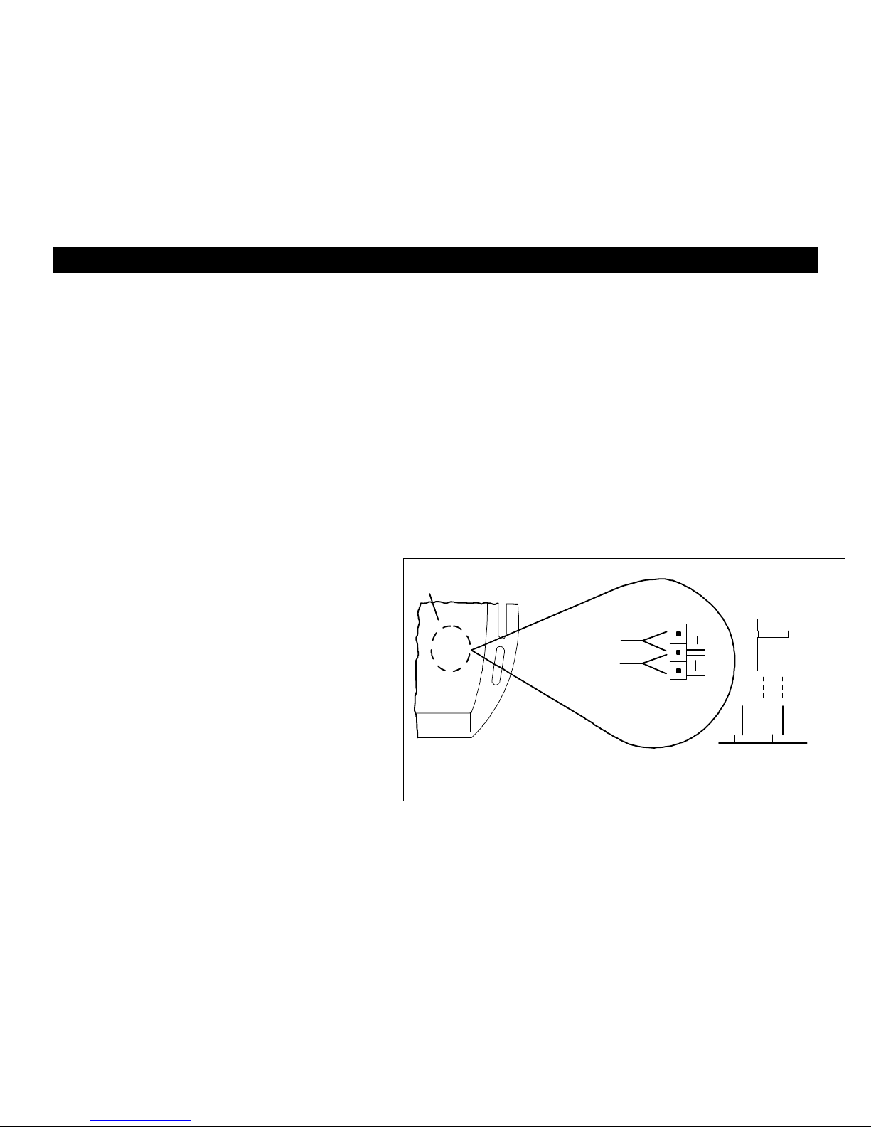
JUMPER
PLUG
SIDE VIEW
JUMPER
PINS
*NEGATIVE DOME
CS855RKE MODULE
POSITIVE DOME
*DEFAULT SETTING IS NEGATIVE
NOTE: DOES NOT APPLY TO CS-845RKE
WIRING
GRAY WIRE: (-) AUXILIARY REMOTE OUTPUT 1 (Optional, requires relay)
Connect to terminal 85 of relay. Connect terminal 86 to constant. Connect terminal 87 to +12V or Ground depending
on the type of circuit that needs to activated. Connect terminal 30 to the device/circuit to be activated. Controlled by
pressing and holding Button (3) Trunk Pop for more than 1 second.
GREEN WIRE: (-) AUXILIARY REMOTE OUTPUT 2 (Optional, requires relay)
This wire connects the same way as Remote Output 1 see GRAY WIRE above. Controlled by Pressing and Holding
Button (1) Lock for more than 1 second.
ORANGE WIRE: NEGATIVE ARMED OUTPUT
This wire provides a GROUND output when system is locked with the remote transmitter. This output can used for an
starter disable relay or a device such as a window roll-up module. For a Starter Disable Circuit, a relay is required.
(Not included) Cut starter wire and connect to terminals 87A and 30 on relay. Connect orange wire to 85 and connect
86 to an IGNITION source that has voltage in the ON and CRANKING position. See Wiring Diagram.
BLACK WIRE: SYSTEM CHASSIS GROUND
THIS WIRE MUST BE CONNECTED TO CHASSIS METAL OF THE VEHICLE. Scrape away any paint or dirt from
the connection point to ensure a good connection. Keep ground wire short and try not to use factory ground locations.
BROWN WIRE 845RKE: (-) DOME LIGHT
ILLUMINATION OUTPUT (Optional, may require
external relay): Connects to Dome light activation
circuit for Negative dome light systems or to terminal
85 of an external relay for Positive circuits.
BROWN WIRE 855RKE: (+ or -) DOME LIGHT
OUTPUT (On-Board Relay): Connect to dome light
activation circuit for Negative type circuits. For
Positive type circuits, open the control module and
switch jumper the plug as shown in illustration >>>.
RED WIRE: +12V POWER INPUT (15 amp fuse)
Connect to +12 Volt source with supplied fuse &
holder. Recommended location for this connection
is at the vehicle battery positive terminal.
WHITE WIRE: +12V FLASHING PARKING LIGHT OUTPUT
Connect to switched parking light wire at back of light switch. If this is not possible, connect directly to one of the
parking lights at the front of the vehicle. European vehicles require separate right and left circuits. Use a dual relay or
2 diodes to separate the output signal.
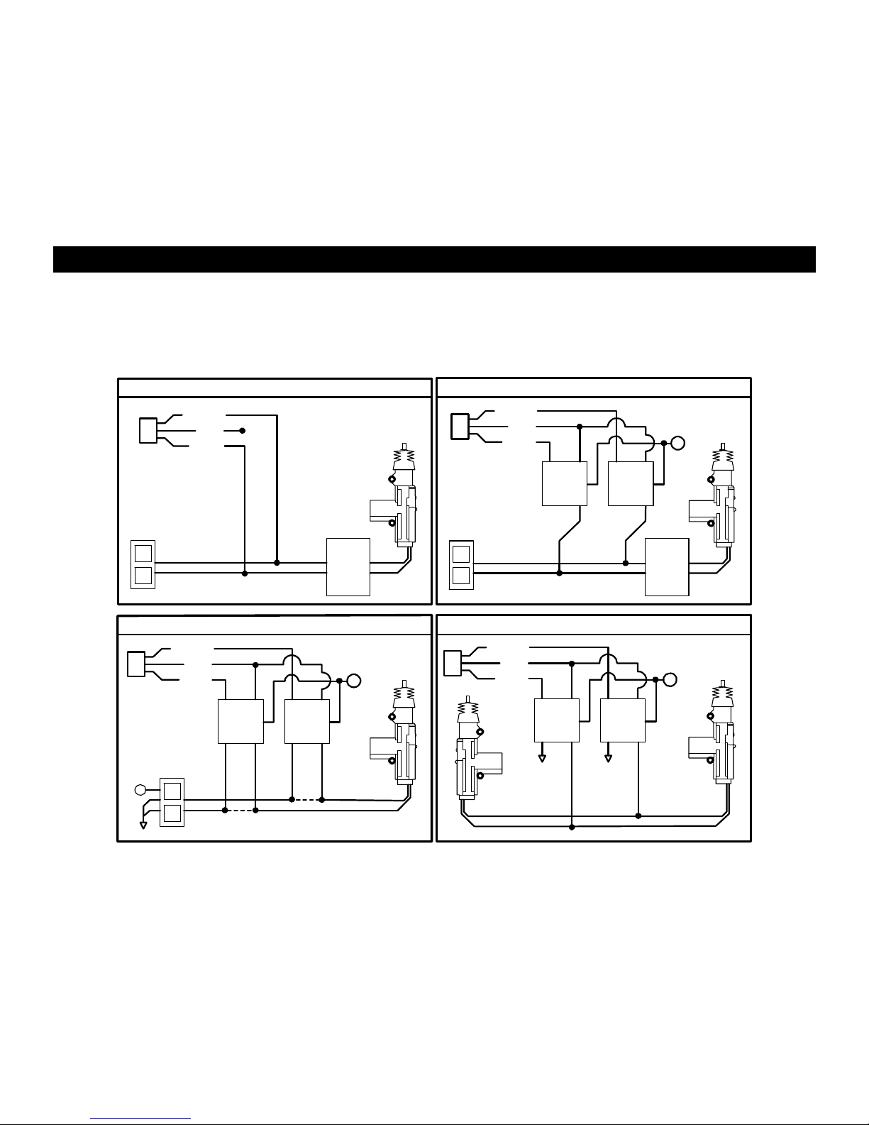
CS-845 RKE POWER DOOR LOCK WIRING
3 PIN (WHITE): DOOR LOCK OUTPUT PLUG
GREEN: (-) Negative LOCK pulse
RED: +12V Coil Power for external relays (Term. 86).
BLUE: (-) Negative UNLOCK pulse
CS-845RKE NEGATIVE TRIGGER DOORLOCK WIRING
CS-845RKE POSITIVE TRIGGER DO ORLOCK WIRING
GREEN
GREEN
FUSED
RED
+12VRED
BLUE
+
BLUE
86
858685
8787
3087A30
87A
FACTORY
FACTORY
L
L
POWER
POWER
LOCKING
LOCKING
UL
UL
RELAYS
RELAYS
CS-845RKE AFTERMARKET DOOR LOCK WIRINGCS-845RKE REV. POLARITY DOOR LOCK WIRING
GREEN
GREEN
FUSED
FUSED
RED
RED
+12V
+12V
BLUE
BLU E
+
+
86858685
868 58685
8787
8787
3087 A3087A
308 7A3087A
+
L
CUT
UL
CUT
MASTER
SWITC H
LOCK WIRE
UNLOCK WIRE
 Loading...