

CrimeStopper CS-2205, CS-2205.ADV, CS-2205ADVTW1 Installation & Operating Instructions Manual
CS-2205ADVTW1 Deluxe 2-Way LED Paging Security System
INSTALLATION & OPERATING INSTRUCTIONS
CONGRATULATIONS on your choice of a Security System by Crimestopper Security Products Inc. This booklet contains
the information necessary for installing, using, and maintaining your CS-2205 Advantage alarm system. If any questions
arise, contact your installation dealer or Crimestopper Security Products Inc. at the Tech Support number below.
This installation book is designed for the installer or individual with an existing understanding of automotive electrical
systems, along with the ability to test and connect wires for proper operation. To ease installation, we suggest that you
READ THIS MANUAL before beginning your installation. This book is provided as a GENERAL GUIDLINE and the
information contained herein may differ from your vehicle.
*IMPORTANT INFORMATION: Primary and Optional Features
-PRIMARY: These are features that must be connected in order for the system to operate properly i.e. Siren, L.E.D., Power,
Ground, Door Pin, and Flashing Lights etc.
-OPTIONAL: These are features are to be connected only if desired or agreed upon by the customer and the installing
dealer (i.e. Door Locks, Starter Disable, Hood/Trunk Protection and Auxiliary Remote Outputs etc.) These features may also
require additional parts and/or labor fees. Consult with your installer beforehand to be sure of what is going to be installed
with your particular system.
TECH SUPPORT
(800) 998-6880
Hours: M-F 8:00AM-4:30PM
Pacific Std. Time
REV B 6.2005
This device complies with FCC Rules part 15. Operation is subject to the following two
conditions: 1) This device may not cause interf
erence, and (2) this device must accept any
interference that may be received, including interference that may cause undesired operation.
The manufacturer is not responsible for any radio or TV interference caused by unauthorized
modification to this equi
pment. Such modification could void the user's authority to operate the
equipment.
SERIES I

2
TABLE OF CONTENTS
Installation Cautions & Warnings…….……………………………………………………………...………………………………..2
Suggested Component Mounting………….…………………………………………………………….……………………….…...3
Wiring (Connectors H1-H8)…………………………………………………………………………………………………………3-12
.Power Door Lock Wiring...………………………………………………………………..……………………………………….…4-6
Starter Disable Wiring…………………………..…..…………………………………………………………..………………….10-11
Antenna Diagram………………….……...…………………………………………………………………….…...…………………13
Option Programming……………..………………………………………………………..…………..…….……………………14-18
Programmable Option Reset………………………...……….…………………………………………………….…………….….16
Main System Wiring Diagram………………….…………………………………………………………………………………….19
Remote Programming……..……………………………………………………..………………………....………………………..20
Operation.………………………..…………………………………..….……………….…………………………………….……21-32
2-Vehicle Operation…….…………………………………..….………………………………….…….…………………………….23
INSTALLATION CAUTIONS & WARNINGS
BEFORE BEGINNING, check all vehicle manufacturer cautions and warnings regarding electrical service (AIR BAGS, ABS
BRAKES, AND BATTERY).
TO PREVENT A POSSIBLE DEAD BATTERY remove vehicle dome light fuse while working on the vehicle. MAKE
CERTAIN TO REINSTALL FUSE PRIOR TO TESTING FOR DOOR TRIGGERS.
DO NOT EXCEED MAXIMUM OUTPUT RATINGS! - SERIOUS DAMAGE MAY OCCUR. LIMITS FOR ALARM FUNCTIONS
ARE LISTED WHERE APPLICABLE.
REMOVE MAIN SYSTEM FUSE (S) before jump starting the vehicle or charging the battery at high boost. DAMAGE MAY
OCCUR TO SYSTEM IF PROPER PRECAUTIONS ARE NOT OBSERVED.
DO NOT Mount the control unit or wiring harness in the engine compartment or anywhere they can become entangled with
moving parts such as brake/gas/clutch pedals, or the steering column. The alarm control module should be mounted in a
concealed location. The antenna wire should be routed away from any metal if possible. Do not alter the length of the
antenna, ground it, or route it with other wires.

3
CONTROL MODULE/COMPONENT MOUNTING
CONTROL MODULE: The alarm control module should be mounted in a concealed location. DO NOT mount the control unit
in the engine compartment. Fasten the module to a bracket or wire harness using the cable ties provided.
ANTENNA MODULE: For optimum range and performance, the antenna/receiver module should be located high up on the
front windshield glass. For example: behind the rearview mirror. Note: Window tint or films may decrease the range of the
system. The mounting surface for the antenna should be clean and dry.
SIREN MOUNTING: Mount the siren under the hood to fender-well or other body surface with the open end facing
downward. Run the red siren wire through the firewall using a rubber grommet. Ground the black wire to the body.
LED: Mount the LED in a visible location on the dashboard or console.
SHOCK SENSOR: Mount the included shock sensor with wire ties to an under dash wire harness or fasten with screws to
firewall or side paneling.
OVERIDE/PROGRAM BUTTON: Mount the Override/Program push-button in a hidden but accessible location. It is used for
emergency disarm without the use of the transmitter and for programming certain features.
(H1) 6-PIN WHITE CONNECTOR
RED WIRE: +12V POWER INPUT (3 Amp Fuse)
Connect to a +12Volt source with the supplied fuse and fuse-holder. We recommend the connection to be at the Vehicle’s
Battery Positive Terminal.
BROWN WIRE: (+) SIREN OUTPUT (3 Amp Max.)
Connect to the siren’s RED wire. Connect the Siren’s Black Ground wire to the chassis close to the siren.
BLACK WIRE: CHASSIS GROUND
THIS WIRE NUST BE CONNECTED TO THE CHASSIS METAL OF THE VEHICLE. Scrape away any paint or dirt to ensure
a good connection.
WHITE WIRE: +12V FLASHING PARKING LIGHT OUTPUT (optional)
Connect to switched parking light wire at back of light switch or connect directly to one of the parking lights at the front of the
vehicle. European vehicles may require additional parts due to separate left and right circuits.
4
RED/WHITE WIRE: INPUT SOURCE FOR FLASHING PARKING LIGHT
Connect to a +12 Volt source or Chassis Ground depending on the vehicle Parking light circuit.
WHITE WIRE: +12V FLASHING PARKING LIGHT OUTPUT (optional)
Connect to switched parking light wire at back of light switch or connect directly to one of the parking lights at the front of the
vehicle. European vehicles may require additional parts due to separate left and right circuits.
(H 2) 4-PIN ORANGE CONNECTOR: SHOCK SENSOR
4-PIN SENSOR PLUG:
RED WIRE: SENSOR +12V POWER
BLACK WIRE: SENSOR GROUND
GREEN WIRE: NEG. WARN-AWAY
BLUE WIRE: NEG. TRIGGER
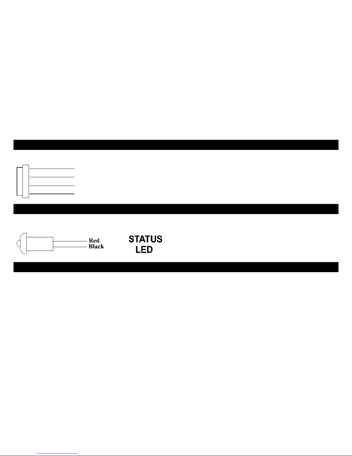
(H 3) 2-PIN WHITE CONNECTOR: LED INDICATOR
LED PLUG: LED Indicator (RED FLASHING LIGHT)
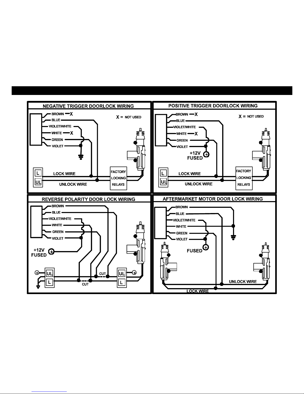
(H 4) 6-PIN WHITE CONNECTOR: POWER DOOR LOCK WIRING
6-PIN DOOR LOCK PLUG 18 GA. (Optional / ON-Board Relays):
BROWN: DOOR UNLOCK Relay Term. #87A: Normally Closed
BLUE: DOOR UNLOCK Relay Term. #30: Common [Unlock Output]
VIO/WHT: DOOR UNLOCK Relay Term. #87: Normally Open [Polarity Input for Unlock relay]
WHITE: DOOR LOCK Relay Term. #87A: Normally Closed
GREEN: DOOR LOCK Relay Term. #30: Common [Lock Output]
VIOLET: DOOR LOCK Relay Term. #87: Normally Open [Polarity Input for Lock relay]

5
(H 4) POWER DOOR LOCK WIRING
DETERMINING DOOR LOCK TYPE: We recommend determining the type of locking system the vehicle has before
connecting any wires. Incorrect connection may result in damage to the alarm and/or vehicle locking system. This door lock
information is provided as a guide. Your vehicle may differ.
Negative Trigger (-): Many Imports; Late model Ford & General Motors
Negative trigger door lock systems send a Negative (Ground) pulse to existing factory relays to lock and unlock the vehicle
doors.
Positive Trigger (+): Many General Motors; Chrysler / Dodge / Plymouth
Positive trigger door lock systems send a Positive (+12V) pulse through factory relays to lock and unlock doors.
Reverse Polarity: Many Ford/Lincoln/Mercury/Dodge/Chrysler/Plymouth and early 90’s GM Trucks
Reverse Polarity systems use no relays, but instead the door lock/unlock motors are controlled directly from the lock and
unlock switches in the door. The lock and unlock wires rest at Negative Ground when not in use. When the lock or unlock
button is pressed, one of the circuits is “Lifted” and replaced with +12V causing a lock or unlock.
Single Wire (Dual Voltage): Late model Chrysler/Dodge/Plymouth Vehicles, some 2000-UP GM
Dual Voltage systems have lock/unlock switches that send varying amounts of Positive voltage OR Negative ground current
to the SAME wire for both lock and unlock. When the vehicle’s Body Computer Module (BCM) or door lock module senses
different voltages on this wire, the system will either lock or unlock. Single wire door lock systems require relays and
resistors.
Databus Systems (2003 GM Trucks & SUV’s, ‘99-05 Jeep Grand Cherokee)
Databus systems send low current “Data messages” to the door lock controllers in order to lock and unlock the vehicle. To
install aftermarket systems in these vehicles, an interface module is required that converts the regular lock/unlock pulses into
“Data messages” to allow locking & unlocking. Interface modules are sold separately.
6
(H 4) POWER DOOR LOCK WIRE DIAGRAM

7
(H 5) ANTENNA/PAGER SWITCH
Transmitter Antenna: Two-way Pager Antenna.
Pager switch: Pages your Two-way pager in an event you lose your keys (Two-way pager only)
(H 6) KNOCK SENSOR (Optional)
KNOCK SENSOR (Optional): Sensor not included in kit.
(H 7) PROGRAM/OVERRIDE BUTTON
2-PIN PLUG (LARGE): PROGRAM/OVERRIDE PUSH BUTTON
PROGRAM/Emergency Override (Disarm)
For Programming:
Used to change options on program table and to code remote:
For Emergency Override:
If you have lost the transmitter or it stops working for any reason and the Alarm is armed, you will have to
Disarm the system manually. Open the door with the key [alarm will sound], turn the ignition on, and press the
Override/program button once. The Alarm will disarm and allow you to use the vehicle until you can repair/replace the
remote. Valet mode also prevents Passive Arming.
8
+12V
+12V
+12V
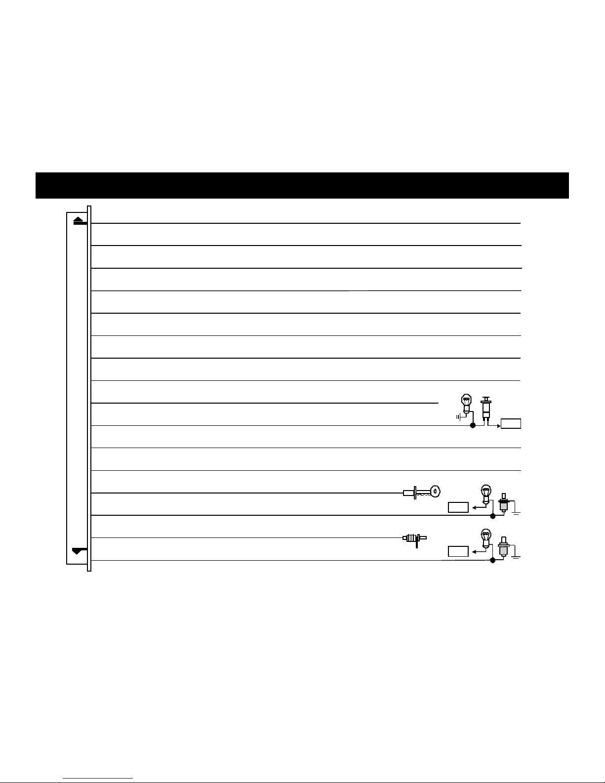
8. Orange/White Wire: (-) 300mA Negative Starter Disable (Normally Open)
7. Blue/White Wire: (-) 200mA Passenger Door Unlock Output (Option, may Require a Relay)
6. Gray Wire: (-) 200mA (Trunk Pop) Auxiliary 1 Output
(Option, may Require a Relay)
15. Blue Wire:
Zone 2
/
Hood Trigger Ground Input
3. Orange/Black Wire:
(-) 200mA Factory Disarm (OEM) Output (Option, may Require a Relay)
2. Black/Violet Wire: (-) 200mA Auxiliary 3 Output (Option, may Require a Relay)
4. Black/Red Wire: (-) 200mA Auxiliary 2 Output (Option, may Require a Relay)
14. Green Wire:
Zone 3 / Negative Door Pin Trigger Input
10. Violet Wire: Zone 3 / Positive Door Pin Trigger Input
9. Orange Wire: (-) 300mA Negative Starter Disable (Normally Close)
1. Black/White Wire:
(-) 200mA Dome light Output (Require a Relay)
13. Yellow Wire:
Zone 5 / To Ignition Switched + 12V
5. Brown/White Wire:
(-) 200mA Horn Honk Output (Option, may Require a Relay)
16. White Wire:
Zone 2 / Trunk Trigger Input
11. White/Black Wire:
Negative Door Unlock Control Input
12. White/Green Wire:
Negative Door lock Control Input
(H8) PIN WIRING DIAGRAM

9
WIRING 16-PIN CONNECTOR
BLACK/WHITE WIRE: DOME LIGHT Illumination Output (Optional, Requires relay)
Negative Dome Light System: Connects to terminal 85 of a relay. Connect terminal 86 + 12V Constant. Connect terminal 87
to Chassis Ground and Connect Terminal 30 to the Negative dome light activation.
Positive Dome Light System: Connects to terminal 85 of a relay. Connect terminals 86 & 87 to + 12V Constant. Connect
terminal 30 to the Positive dome light activation circuit.
BLACK/VIOLET WIRE:(-) NEGATIVE AUX REMOTE OUTPUT 3 (Optional, may require a relay)
Negative output when the unlock and trunk button is press at the same time. This wire connects the same way as Remote
Output 1 see GRAY WIRE description below. (To change the functions of this output go to program option number 21).
ORANGE/BLACK WIRE:(-) FACTORY OEM DISARM OUTPUT
This wire provides a Ground pulse to disarm vehicles’ Factory anti-theft system. Connect this wire to the vehicles’ anti-theft
disarm wire. This wire is sometimes found coming off the Driver’s door key switch or at the Factory Anti-theft control module.
BLACK/RED WIRE: (-) NEGATIVE AUX REMOTE OUTPUT 2 (Optional, may require a relay)
Negative output when the lock and trunk button is press at the same time. This wire connects the same way as Remote
Output 1 see GRAY WIRE description below. (To change the functions of this output go to program option number 20).
BROWN/WHITE WIRE: (-) HORN HONK OUTPUT (Optional, may require a relay)
Connect to the Negative Horn Trigger wire usually located near the steering column. If the vehicle horn circuit requires +12V,
then a relay is required. RELAY WIRING: Connect the Brown/White wire to terminal 85; connect relay terminals 86 and 87 to
+12V constant power. Connect terminal 30 of the relay to the +12V positive device/circuit to be activated.
GRAY WIRE: GRAY WIRE: (-) NEGATIVE AUX REMOTE OUTPUT 1 (Optional, may require a relay)
This will become a 1 second pulse ground by pressing the trunk button on the transmitter for three seconds. The current
capacity of this wire is 200mA. This feature allows you to remote control trunk release or other electric device. This output
can also by program to provide the following type of output: latched and timed control output. (To change the functions of this
output go to program option number 19).
BLUE/WHITE WIRE: (-) PASSENGER(s) DOOR UNLOCK OUTPUT (Optional, requires relay)
Connects to unlock circuit for passenger door(s) when using separate driver’s door unlock option. Double press unlock button
within 2 second to activate passenger unlock output.

10
ORANGE/WHITE WIRE: NEGATIVE STARTER DISABLE (Normally Open)
This wire should be connected to the Orange wire of the pre-wired relay socket for the starter disable. Connect the Yellow
wire of the relay socket to the Ignition switched wire on the vehicle. Remove the white wire from the relay socket with a small
flat head screwdriver an insert it in pin # 87. Cut the vehicle starter wire and connect each half to the Red and White wire on
the relay socket. See (Normally Open) Starter disable diagram on page 11.
ORANGE WIRE: (-) NEGATIVE STARTER DISABLE (Normally Close)
This wire should be connected to the Orange wire of the pre-wired relay socket for the starter disable. Connect the Yellow
wire of the relay socket to the Ignition switched wire on the vehicle. Cut the vehicle starter wire and connect each half to the
Red and white wire on the relay socket. See (Normally Close) Starter disable diagram on page 11.
Note: READ BELOW before connecting starter disable! Normally OPEN use Orange/White wire. For Normally Close
use Orange.
Normally Closed Starter disable is the standard type used with most alarm systems today. This circuit will disable the
Starter while the alarm is armed or has been triggered. If 12V power is removed from the system, the Battery goes dead; the
relay will revert back to the closed position. See Normally Close Diagram.
Normally Open Starter Disable is a High-Security circuit that will disable the starter while the alarm is armed or triggered
AND if the unit is unplugged or removed from power. This means that if the vehicle’s Battery goes dead or the unit is
unplugged from the vehicle, the car will still not start. We only recommend this type of circuit if you can install a hidden highcurrent toggle switch to defeat the Normally Open disable in case of a dead battery or if the unit is unplugged/remove for
service. (Toggle not included) See Normally Open Diagram.
 Loading...