

CrimeStopper CS-2011RS.III Installation Instructions Manual

CS-2011RS Series III / CS-2015FM
Super Rage™ The Informer™
INSTALLATION INSTRUCTIONS
INTRODUCTION
Congratulations on your choice of a Crimestopper combo alarm & remote engine starter! This installation Handbook
covers the following models: CS2011RS Series III & CS2015FM Informer 2-Way FM paging system.
This installation book is designed for the installer or individual with an existing understanding of automotive electrical
systems, along with the ability to test and connect wires for proper operation. To ease installation, we suggest that
you READ THIS MANUAL before beginning your installation. This book is provided as a GENERAL GUIDLINE and
the information contained herein may differ from your vehicle!
DISCLAIMER:
Crimestopper Security Products, Inc. and its vendors shall not be liable for any accident resulting from the
use of this product. This system is designed to be professionally installed into a vehicle in which all
systems and associated components are in perfect working condition.
TECHNICAL SUPPORT (800)-998-6880
Monday - Friday 8:00am - 4:30pm Pacific
Website: www.crimestopper.com
E-mail: email@crimestopper.com
CRIMESTOPPER SECURITY PRODUCTS, INC.
1770 S. TAPO STREET
SIMI VALLEY, CA. 93063
REV A 8.2002 S/W: 2011-620 / 2015-618
This device complies with FCC Rules part 15. Operation is
subject to the following two conditions: 1) This device may not
cause interference, and (2) this device must accept any
interference that may be received, including
interference that
may cause undesired operation. The manufacturer is not
responsible for any radio or TV interference caused by
unauthorized modification to this equipment. Such
modification could void the user's authority to operate the
equipment.

TABLE OF CONTENTS
Pre-Installation Considerations…………………...….…...…………...……………………………………………………….2
Cautions & Warnings…….…………………………..…..………………………………………………………………………3
Component Mounting………….……………………..……………………………………………….…………………..……..3
Wiring Information………….…………………………....……………...……………………………………………..…….4-10
Power Door Lock Wiring, Systems & Diagrams..….………………...….………..…….……..…………...……………10-13
Smart Tachless, Tach Reference, Tach Finder, Timed Crank Mode……….…………………………………………14-16
Diesel Glow Plug Delay………………………………………………………………………………………………...………17
Programmable Options……...……………………………………………………………………….………….…………17-21
Remote Transmitter / Transceiver Programming (CS-2011RS & CS-2015FM)………………………...…...…...….21-22
Alarm Trigger Diagnostics…………………....…………………………………………………………………….………….22
2 Vehicle Operation……………………………………………………………………………………………………...……..23
Remote Start Troubleshooting…….……………………..……………………………………………………………...…….24
Jumper Pin Diagram…………………………………………………………………………………………………………....25
Antenna Diagram…………………………………………………………………………………………………………….....26
System Wiring Diagram……………………………………………………...………………………………………...………27
PRE-INSTALLATION CONSIDERATIONS
BEFORE BEGINNING, check all vehicle manufacturer cautions and warnings regarding electrical service (AIR
BAGS, ABS BRAKES, ENGINE / BODY COMPUTER AND BATTERY).
PLAN OUT YOUR INSTALLATION. You should pre-determine the location of the Control Module (Brain), Valet
button, LED, and Siren locations. This will save time and ease the installation process.
USE A VOLT/OHM METER to test and locate all connections. Test Lights or Lighted Probes could possibly
damage a vehicle’s computer system or cause an airbag to deploy.
ADDITIONAL PARTS, that are not included with this unit, may be needed for your particular vehicle. These items
may include extra relays, Door Lock Interface Modules, or Transponder Override modules.

CAUTIONS & WARNINGS
DAMAGE RESULTING FROM IMPROPER INSTALLATION IS NOT COVERED UNDER WARRANTY!!
DO NOT remote start the vehicle in a closed garage. Make sure that the garage door is open or there is adequate
ventilation. Failure to observe this rule could result in injury or death from poisonous Carbon Monoxide fumes.
DO NOT ROUTE ANY WIRING THAT MAY BECOME ENTANGLED with the brake/gas pedals, steering column, or
any other moving parts in the vehicle.
REMOVE MAIN SYSTEM FUSE(S) before jump-starting the vehicle or charging the battery at high boost. DAMAGE
MAY OCCUR TO SYSTEM IF PROPER PRECAUTIONS ARE NOT OBSERVED.
DO NOT exceed the rated output current of any circuit on the Remote start module. Failure to observe this warning
will result in damage to the unit. Output currents are listed where applicable throughout this manual.
DO NOT extend the Remote start ignition harness length. Mount the module so that main harness reaches all
ignition switch wiring. Extending these wires could result in poor performance.
COMPONENT MOUNTING
CONTROL MODULE: The alarm control module should be mounted in a concealed location. DO NOT mount the
control unit in the engine compartment. Fasten the module to a bracket or wire harness using the cable ties
provided.
ANTENNA MODULE: For optimum range and performance, the antenna/receiver module should be located high up
on the front windshield glass. For example: behind the rearview mirror. Note: Window tints or Films may decrease
the range of the system. The mounting surface for the antenna should be clean and dry.
SIREN MOUNTING: Mount the siren under the hood to fender-well or other body surface with the open end facing
downward. Run the red siren wire through the firewall using a rubber grommet. Ground the black wire to the body
metal near the siren.
LED: Mount the red LED in a visible location on the dashboard or console.
SHOCK SENSOR: Mount the included shock sensor with wire ties to an under dash wire harness or fasten with
screws to firewall or side paneling.
OVERRIDE/PROGRAM/VALET BUTTON: Mount the Override/Program push-button in a hidden but accessible
location. This button is required for emergency disarm, programming, and valet mode.

WIRING: 9-PIN Connector
Green: (-) Start Activation Trigger Input
This wire allows an outside source or accessory to activate a Remote Start. A 1-second Ground pulse on this wire
will trigger a remote start. This wire can be used with optional accessories such as RS400 temperature module.
Brown: (+) Siren Output
Connect brown wire to siren red wire. Connect black wire of siren to chassis ground (body metal).
Brown/White: (-) Horn Honk Output (Optional, may require a relay)
Connect to the Negative Horn Trigger wire usually located near the steering column. If the vehicle horn circuit
requires +12V, then a relay is required. RELAY WIRING: Connect the Brown/White wire to terminal 85, connect
relay terminals 86 and 87 to +12V constant power. Connect terminal 30 of the relay to the +12V positive
device/circuit to be activated.
Black/White: (-) 500mA Dome Light Illumination Output (Optional, Requires relay)
Negative Dome Light System: Connects to terminal 85 of a relay. Connect terminals 86 +12V Constant.
Connect terminal 87 to Chassis Ground and Connect Terminal 30 to the Negative dome light activation circuit.
Positive Dome Light System: Connects to terminal 85 of a relay. Connect terminals 86 & 87 to +12V Constant.
Connect terminal 30 to the Positive dome light activation circuit. On some vehicle with a single, small dome light
and Negative door trigger cirsuit, this wire may be connected directly to door Negative Door trigger wire
HOWEVER, we recommend the use of a relay to protect from shorting the circuit
Green/Red: Remote Aux. Output 1 OR MAP-Mobile Accessories Protection (Optional, requires relay)
This is a programmable output that can operate two different ways: 1. (DEFAULT) A Remote Auxiliary Output that
provides a ½ Second (-) Negative pulse when Button #3 is pressed to open a Factory power trunk or hatch release.
It can function as an MAP output that provides a continuous (-) Negative output when in the system is put into
VALET PARK MODE. M.A.P. can be used to interrupt power/accessory wiring to prevent unauthorized access of
the vehicle’s audio or entertainment systems when Valet Park mode is ON. See Mobile Accessories Protection
Diagram on Next Page.
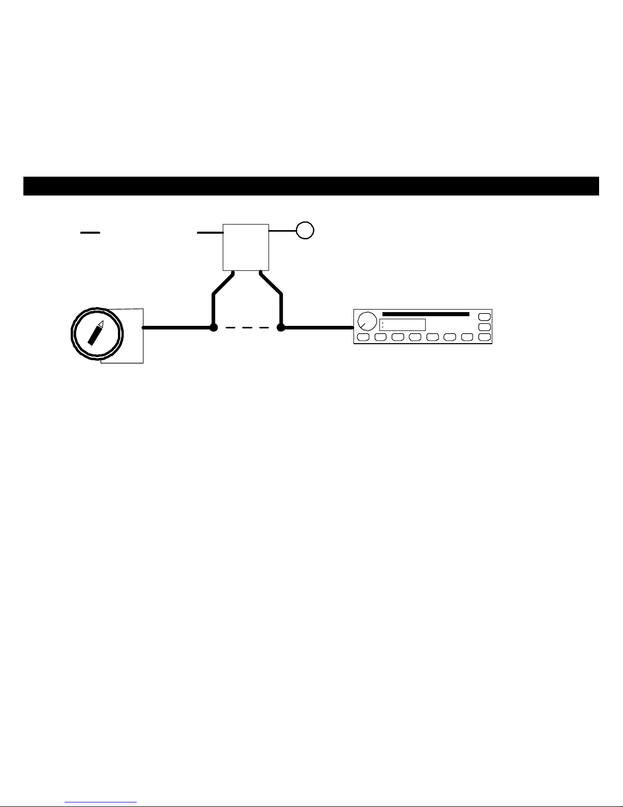
WIRING: 9-PIN Connector
MOBILE ACCESSORY PROTECTION:
8685
+
IGN.
87
SWITCHED
3087A
START
IGN
ACC
CUT
OFF
FM
105.5
wire of mobile accessories such as Audio system
Connect relay as shown to interrupt the power
RADIO
GREEN/RED
M.A.P. OUTPUT
MOBILE ACCESSORY PROTECTION
or Cellular telephone. The Alarm will disconnect
these accessories when in VALET PARK MODE.
Blue/Black: (-) Remote Aux. Output 2 (Optional, may require relay)
This wire provides a Momentary (-) Negative output when Button #3 (Trunk) is pressed and held for more than 2
seconds. Output stays on as long a remote button is held down. Connect to the Negative activation circuit of an
auxiliary module or device. If the circuit requires +12V, then a relay is required. RELAY WIRING: Connect the
Blue/Black wire to terminal 85, connect relay terminals 86 and 87 to +12V constant power. Connect terminal 30 of
the relay to the +12V positive device/circuit to be activated.
Blue/White: (-) Passenger Door Unlock Output (Optional, requires relay)
This wire activates when the unlock button on the remote is pressed a second time upon disarming. This wire is
used for the Optional Separate Driver’s/Passenger Unlock feature. Connects to unlock circuit for passenger door or
doors. See DOOR LOCK WIRING for special configuration options.
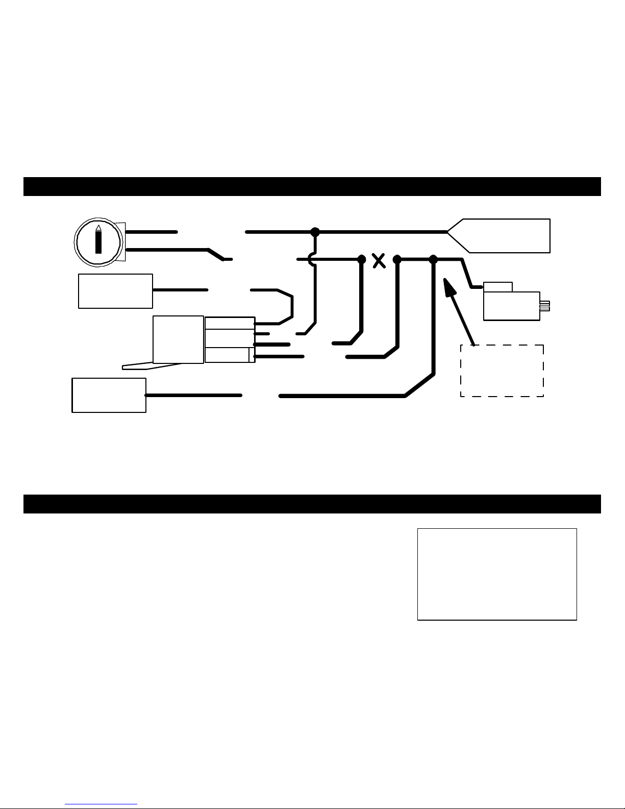
Orange: (-) Negative Starter Disable/Negative Ignition/Anti-Grind Output
This wire should be connected to the Yellow wire of the pre-wired relay socket for the starter disable. Connect the
blue wire of the relay socket to the Ignition switched wire on the vehicle. Cut the vehicle starter wire and connect
each half to an Orange wire on the relay socket. This output also turns on with remote start and functions as a
“Negative when Running” wire. See diagram on next page.
WIRING: 9-PIN Connector
STARTER DISABLE:
CUT
STARTER WIRE
STARTER
ORANGE
ORANGE
CONNECT TO
PRE-WIRED
OF ALARM
IGN. SWITCHED
BLUE
YELLOW
ORANGE WIRE
STARTER DISABLE
RELAY & SOCKET
IGNITION SWITCHED
"ON" & HOT THROUGH
CRANKING
BROWN
START OUTPUT
6-PIN HARNESS
FROM ALARM
MAKE CERTAIN TO
CONNECT BROWN
WIRE TO STARTER
MOTOR SIDE!!!
Orange/Black: (-) OEM Disarm Output
This wire provides a Ground pulse to disarm vehicles' Factory anti-theft system prior to a Remote Start. Connect
this wire to the vehicles' anti-theft disarm wire. This wire is sometimes found coming off the Driver's door key switch
or at the Factory Anti-theft control module.
WIRING: 6-PIN High Current Connector
\
PIN 1: BROWN: STARTER OUTPUT (30A Max.)
PIN 2: GRAY: ACCESSORY (HEAT/AC) (30A)
PIN 3: RED: +12V POWER INPUT (BATTERY) FUSED (30A)
PIN 4: RED: +12V POWER INPUT (BATTERY) FUSED (30A)
PIN 5: PINK: IGNITION 1 (30A Max.)
PIN 6: PINK/WHITE: IGNITION or ACCESSORY #2 OUTPUT (30 Max.)
NOTE!: Use External Relays
for High Current Ignition
and/or Accessory circuits
greater than 30A. Failure to
do so could result in damage
to the unit that is not covered
under warranty.

WIRING: 6-PIN High Current Connector
FUSE
RED
PINK/WHITE
30A
FUSE
RED
30A
+
-
BROWNPINK
FUEL
ENGINE
BATTERY
PUMP
ECU
GRAY
+
STARTER
-
COIL
IGN
OR
ACC
H/V/AC
Diagram not to scale,
for illustration purposes
only. Your vehicle may
differ.
IGN 2
ACC 2
IF NECESSARY
NOTE!: Use External Relays for High Current Ignition and/or Accessory
circuits greater than 30A. Failure to do so could result in damage to the
unit that is not covered under warranty.

WIRING: 3-PIN Connector
White/Red: Tachometer Input
When installing this system in TACH REFERENCE mode, this wire must be connected to a valid source of AC
voltage. This wire allows the unit to sense the engine running. See Tach Reference Section on Pg. 13 for more
information.
Black: Chassis Ground
Connect to body metal of the vehicle using a sheet metal screw and a star washer to ensure a good ground. Keep
the Ground wire short. Scrape away and paint or debris from ground location.
WHITE: +12V or (-) NEGATIVE PARKING LIGHT OUTPUT:
Connect to vehicle parking light circuit at the back of light switch or if this is not possible, connect directly to one of
the parking lights at the front of the vehicle. If your vehicle has a multiplex lighting system that requires a (-)
Negative parking light output, then move the jumper from (+) to (-). See Jumper Pin Diagram. Some European
vehicles require separate left and right circuits. Use a dual relay or diodes to isolate the output.
NOTES: (1) Default parking light output is +12 volts. (2) Use an external relay for vehicles that draw excess
current from extra running lights, light bars, or trailers. Parking light output is limited to +10 or -.5 AMPS
only.
WIRING: 5-PIN Connector
Violet: (+) Door Pin Switch Input
Same as the GREEN wire below except this wire is used for vehicles that show a positive voltage (12 volts) when
the door is open and a ground when doors are closed as in many Ford, Lincoln, and Mercury vehicles.
Green: (-) Door Pin Switch Input
Identify the wire that reads ground when any door is open and 12 volts when all doors are closed. Some vehicles
may have isolated door triggers. In this case you may need to run additional wires from other doors or go directly to
the wire that triggers the vehicle’s interior dome light. Sometimes newer vehicles contain a separate body control
module (BCM) where the door trigger circuit can be located. Most vehicles will NOT require the use of BOTH Green
and Violet door trigger wires.
Blue: (-) Hood/Trunk Pin Switch Input
Input trigger for a grounding hood or trunk pin switch. Connect to existing hood and trunk pin switches that read
ground when open. If no existing switches are available, install new pin switches if desired. Note: DO NOT mount
new pin switches in water pathways.
WIRING: 5-PIN Connector
Pink: (+12V) +/- Diesel Glow Plug Input or Car Jack Input (Programmable Input Wire)
+/- Glow Plug Input (Diesel Vehicles Only)
Connect Pink wire to indicator circuit that shows a (- or +) Signal while the “WAIT TO START LAMP” is on.
When this wire is used, the CS2011RS/2015FM system will wait until light turns off before attempting a remote
start. Note: This input is jumper selectable for Positive or Negative type signals. See Jumper Pin diagram for
jumper configuration.
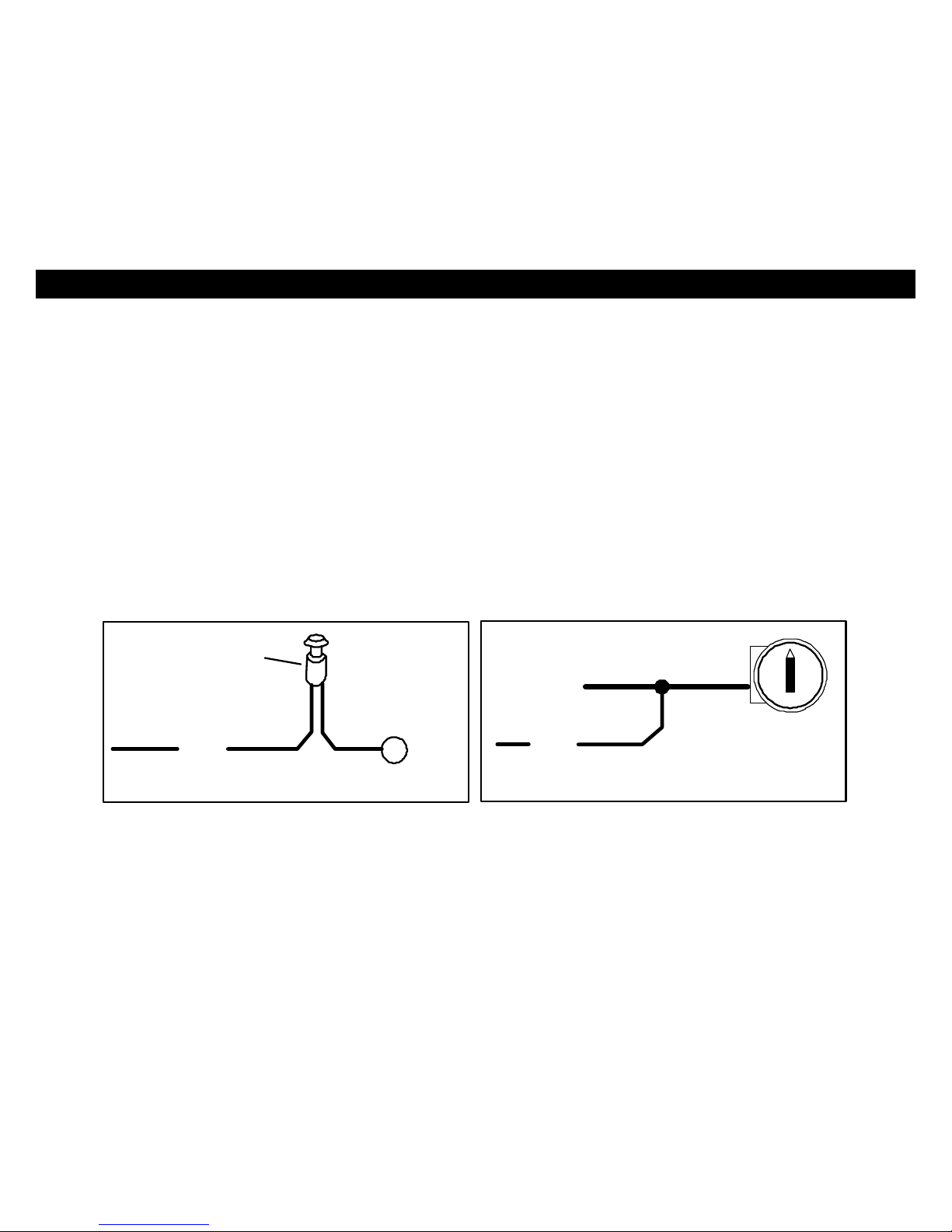
Carjack Trigger
When using Carjack protection, connect this Pink wire to a toggle switch, or positive door trigger or ignition
depending on your level of Carjack protection. When +12V is applied to this wire, with the IGN on, then
Carjack is armed. If a door is opened then closed, a Carjack countdown will begin. See Diagram Below for
wiring configurations. DO NOT connect the Pink Carjack wire to Ignition unless there is extreme danger of a
Carjack. When using the Ignition, Carjack is armed all the time and must be reset each time a door is opened
and closed.
+
12 V
PINK
OPTIONAL CAR JACK WIRING:
HIDDEN BUTTON or
TOGGLE SWITCH
(Not Included)
IGN SW
+ IGN
CONTROLLED W/SWITCH
PINK
FULL-TIME CARJACK
White: (+12V) Brake Reset
Connect the White wire to the side of brake pedal switch that shows +12 volts ONLY when pedal is depressed. This
will turn off the remote start if someone attempts to drive the car without the keys or if the Ignition key is not turned
on all the way.
 Loading...