

CrimeStopper CS-2004 WDC Installation And Operating Instructions Manual

CS-2004 WDC
Remote Control Alarm System with CoolGlow & SecurWatch®
INSTALLATION & OPERATING INSTRUCTIONS
INTRODUCTION:
CONGRATULATIONS on your choice of a Remote Alarm System by Crimestopper Security Products Inc.
This system features both a 4-Button CoolGlow Transmitter and a SecurWatch® Sports Watch
Transmitter that feature anti code-grabbing technology. The remote code changes with every use of the
transmitter making it impossible to scan or record the codes for use later on. This booklet contains the
information necessary for installing, using, and maintaining the many features of this alarm system. If any
questions arise, contact your installation dealer or Crimestopper Security Products Inc. at the Tech Support
number below.
*IMPORTANT INFORMATION: Primary and Optional Features
-PRIMARY: These are features that must be connected in order for the system to operate properly i.e. Siren,
L.E.D., Power, Ground, Doorpin, etc.
-OPTIONAL: These are features to be connected only if desired or agreed upon by the installing dealer (i.e.
Door Locks, Flashing Lights, Starter Kill, Hood, Trunk, and Auxiliary Remote Outputs etc.)
*NOTE: If the system is programmed for Carjack Protection, AUX 1 will not be available when using the
SecurWatch® Remote Transmitter. AUX 1 can still be operated with the 4-Button CoolGlow transmitter
when the system is setup for Carjack.
This device complies with FCC Rules part 15. Operation is subject to the following
two conditions: 1) This device may not cause interference, and (2) this device
must accept any interference that may be received, including interfere
nce that may
cause undesired operation. The manufacturer is not responsible for any radio or
TV interference caused by unauthorized modification to this equipment. Such
modification could void the user's authority to operate the equipment.

TABLE OF CONTENTS
Installation Cautions & Warnings…….………………………………………………………………………………3
Suggested Component Mounting………….…………………………………………………………….…………..3
Wiring……..……………………………………………………………………………………………………….…….4-5
Carjack Wiring………………..……………………………………………………………………………………..……5
Wiring-Mini Plugs………………………………………………………………………………………………………..6
Power Door Lock Wiring...………………………………………………………………..……………………………6
Power Door Lock Diagrams…………………………………….………………………………………………...……7
Starter Disable Wiring…………………………..…..…………………………………………………………………..8
Jumper Plug Programming……………..…………………………………………………………………….……9-11
Transmitter Programming……..………………………………………………………………………..…………….11
Operation………………………………..………………………………………………….………………………..12-14
Carjack Operation……………………………………………………………………………………..………………..15
System Wiring Diagram………………….……………………………………………………………………………16
TECHNICAL SUPPORT (800)-998-6880
Monday - Friday 8:00am - 4:30pm Pacific Standard Time
Website: www.crimestopper.com
E-mail: tech-support@crimestopper.com
CRIMESTOPPER SECURITY PRODUCTS, INC.
1770 S. TAPO STREET, SIMI VALLEY, CA. 93063

INSTALLATION CAUTIONS & WARNINGS
BEFORE BEGINNING, check all vehicle manufacturer cautions and warnings regarding electrical service (AIR
BAGS, ABS BRAKES, AND BATTERY).
TO PREVENT A POSSIBLE DEAD BATTERY remove vehicle dome light fuse while working on the vehicle.
MAKE CERTAIN TO REINSTALL FUSE PRIOR TO TESTING FOR DOOR TRIGGERS.
DO NOT EXCEED MAXIMUM OUTPUT RATINGS! - SERIOUS DAMAGE MAY OCCUR. LIMITS FOR
ALARM FUNCTIONS ARE LISTED WHERE APPLICABLE. IF UNSURE ABOUT CURRENT LOAD,
MEASURE LOAD WITH AN AMP-METER.
REMOVE MAIN SYSTEM FUSE(S) before jump starting the vehicle or charging the battery at high boost.
DAMAGE MAY OCCUR TO SYSTEM IF PROPER PRECAUTIONS ARE NOT OBSERVED.
DO NOT ROUTE ANY WIRING THAT MAY BECOME ENTANGLED with brake, and gas pedals, steering
column, or any other moving parts in the vehicle.
CONTROL MODULE / COMPONENT MOUNTING
DO NOT Mount the control unit in the engine compartment.
DO NOT Mount the control unit or wiring harness where they can become entangled with moving parts
such as brake/gas/clutch pedals, or the steering column.
The alarm control module should be mounted in a concealed location. The Placement of the module will
affect the distance from which the remote transmitter can control the unit. The antenna wire should be routed
away from any metal if possible. Do not alter the length of the antenna wire or route it with other wires. Do
not ground the antenna wire.
SIREN MOUNTING: Mount the siren under the hood to fender-well or other body surface with the open end facing
downward. Run the red siren wire through the firewall using a rubber grommet. Ground the black wire to the body
metal near the siren.
LED: Mount the red LED in a visible location on the dashboard or console.
Shock Sensor: Mount the included shock sensor with wire ties to an under dash wire harness or fasten with screws to
firewall or side paneling.
Override/Program Button: Mount the Override/Program push-button in a hidden but accessible location. It is used
for emergency disarm without the use of the transmitter and for programming certain features.

WIRING
RED WIRE: +12V POWER INPUT (15 Amp Fuse)
Connect to a +12 Volt source with the supplied fuse and fuse-holder. We recommend the connection to be at the
Vehicle’s Battery Positive Terminal.
BLACK WIRE: CHASSIS GROUND
THIS WIRE MUST BE CONNECTED TO THE CHASSIS METAL OF THE VEHICLE. Scrape away any paint or dirt to
ensure a good connection. We recommend the kick panel area for your ground point.
YELLOW WIRE: IGNITION SWITCHED “ON” and “START” +12 VOLTS
Connect to a (+) Ignition Wire that shows +12 Volts when the key is in both the “ON” and “Cranking” positions.
ORANGE WIRE: (-) NEGATIVE ARMED OUTPUT
Ground output when system is armed. This output can be used for additional starter disable relay or to activate other
devices such as scanner LED’s, window modules, voice modules etc.
WHITE WIRE: +12V FLASHING PARKING LIGHT OUTPUT (Optional)
Connect to switched parking light wire at back of light switch or connect directly to one of the parking lights at the front
of the vehicle. European vehicles may require additional parts due to separate left and right circuits.
BROWN WIRE: (+) SIREN OUTPUT (3 Amp Max.)
Connect to the siren’s RED wire. Connect the Siren’s Black Ground wire to the chassis close to the siren.
BLUE WIRE: (-) HOOD/TRUNK TRIGGER
Input trigger for a grounding hood or trunk pin switch. Connect to existing hood and trunk pin switches that read
ground when open. If no existing switches are available, install new grounding pin switches if desired. Note: DO NOT
mount new pin switches in water drainage or pathways.
GREEN WIRE: (-) DOOR TRIGGER
Connect to Negative type door switches that read ground when a door is opened and 12 volts when all doors are
closed. In the case of isolated door triggers, you may need to run additional wires from other doors OR go directly to
the wire that triggers the vehicle’s dome light.
VIOLET WIRE: (+) DOOR TRIGGER
Connect to Positive type door switches that show +12 Volts when the door is open and Ground when the doors are
closed. (Many Ford vehicles.)
GRAY WIRE: (-) REMOTE OUTPUT 1 (Optional, Requires Relay)
Connect this wire to terminal 85 of a relay to operate AUX device or function. Connect terminal 86 or the relay to +12
Volts constant. Connect terminal 87 to 12Volts or Ground depending to the type of circuit needed. Connect Terminal
30 to the AUX device’s activation wire. This output will provide a ½ second ground pulse when AUX 1 is activated.
WIRING
WHITE/RED WIRE: (-) REMOTE OUTPUT 2 (Optional, Requires Relay)
Connects the same way as Remote Output 1 above to activate or control a second AUX device or function. This
output will provide a momentary negative signal when AUX 2 is activated.
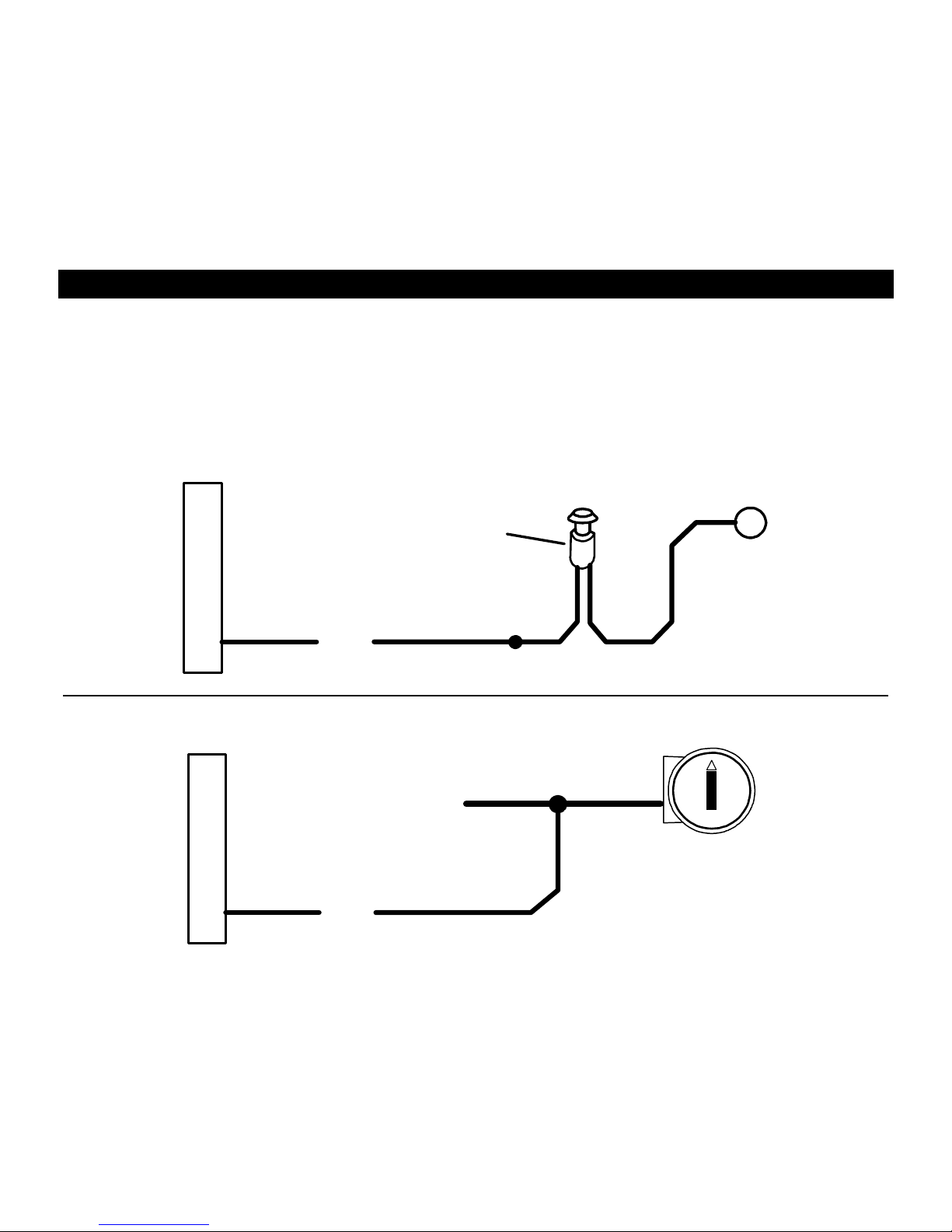
PINK WIRE: (+) CARJACK ENABLE
Connect to push button, toggle switch, or to a +12 Volt source to activate Car Jack protection features See diagrams
below for possible wiring configurations.
+
+12 V
PINK
OPTIONAL CAR JACK WIRING: SWITCH
HIDDEN BUTTON or
TOGGLE SWITCH
(Not Included)
IGN SW
PINK
OPTIONAL CAR JACK WIRING:
FULL TIME
+ IGN

WIRING – MINI PLUGS
2-PIN PLUG (SMALL): LED INDICATOR (RED FLASHING LIGHT)
2-PIN PLUG (MEDIUM): PROGRAM/OVERRIDE PUSH BUTTON
4-PIN SENSOR PLUG:
RED WIRE SENSOR +12V POWER
BLACK WIRE SENSOR GROUND *The Sensor supplied with the system does not require
BLUE WIRE: NEG. WARN AWAY any additional wiring, simply mount the sensor in a
WHITE WIRE: NEG. TRIGGER suitable location, plug in, and adjust sensitivity.
3-PIN SENSOR #2 PLUG: (For adding additional sensors)
PIN 1: SENSOR +12V POWER
PIN 2: NEGATIVE (-) TRIGGER
PIN 3: SENSOR GROUND
3 PIN PLUG (BROWN): NOT USED
POWER DOOR LOCK WIRING
6-PIN DOOR LOCK PLUG 18 GA. (Optional / ON-Board Relays):
VIOLET: DOOR LOCK Relay Term. #87: Normally Open [Polarity Input for Lock relay]
WHITE: DOOR LOCK Relay Term. #30: Common [Lock Output or Motor Side with Rev. Polarity]
GRAY: DOOR LOCK Relay Term. #87A: Normally Closed [Switch side with Rev. Polarity]
VIOLET/WHITE: DOOR UNLOCK Relay Term. #87: Normally Open [Polarity Input for Unlock relay]
GREEN: DOOR UNLOCK Relay Term. #30: Common [Unlock Output or Motor Side with Rev. Polarity]
BLUE: DOOR UNLOCK Relay Term. #87A: Normally Closed [Switch side with Rev. Polarity]
DETERMINING DOOR LOCK TYPE: We recommend determining the type of locking system the vehicle has before
connecting any wires. Incorrect connection will result in damage to the alarm and/or vehicle locking system. There are
several types of door lock systems in vehicles today. Below is listed the many types of common locking systems:
Negative trigger: Most Japanese; Ford, New GM Positive trigger: Many GM; Some Chrysler
One wire dual voltage: Newer /Chrys/Dodg/Plym; Ford Probe
Reverse Polarity: Chrys/Dodg/Plym; GM; Ford Ground/open: Some Nissan; Subaru
Semi-automatic: Older Saab and Volvo Electric vacuum pump: Pre-‘95 Mercedes-Benz
 Loading...