

Page 1

This device complies with FCC Rules part 15. Operation is subject to the following
, including interference that may
CS-2003DC
REMOTE CONTROL ALARM SYSTEM
INSTALLATION & OPERATING INSTRUCTIONS
INTRODUCTION
CONGRATULATIONS on your choice of a Gargoyle™ Remote Alarm System by Crimestopper Security
Products Inc. This system features DYNAMIC CODE anti code-grabbing technology. The remote control
code changes with every use of the transmitter making it impossible to scan or record the codes for use later
on. This booklet contains the information necessary for installing, using, and maintaining your alarm system.
If any questions arise, contact your installation dealer or Crimestopper Security Products Inc. at the Tech
Support number below.
*IMPORTANT INFORMATION: Primary and Optional Features
-PRIMARY: These are features that must be connected in order for the system to operate properly i.e. Siren,
L.E.D., Power, Ground, Doorpin, etc.
-OPTIONAL: These are features to be connected only if desired or agreed upon by the installing dealer (i.e.
Door Locks, Flashing Lights, Starter Kill, Hood, Trunk, and Auxiliary Remote Outputs etc.)
TECH SUPPORT
Mon-Fri 8:00 AM-4:30 PM Pacific Time
(800) 998-6880
two conditions: 1) This device may not cause interference, and (2) this device
must accept any interference that may be received
cause undesired operation. The manufacturer is not responsible for any radio or
TV interference caused by unauthorized modification to this equipment. Such
modification could void the user's authority to operate the equipment.
Page 2

INSTALLATION CAUTIONS & WARNINGS
BEFORE BEGINNING, check all vehicle manufacturer cautions and warnings regarding electrical service (AIR
BAGS, ABS BRAKES, AND BATTERY).
TO PREVENT A POSSIBLE DEAD BATTERY remove vehicle dome light fuse while working on the vehicle.
MAKE CERTAIN TO REINSTALL FUSE PRIOR TO TESTING FOR DOOR TRIGGERS.
DO NOT EXCEED MAXIMUM OUTPUT RATINGS! - SERIOUS DAMAGE MAY OCCUR. LIMITS FOR
ALARM FUNCTIONS ARE LISTED WHERE APPLICABLE. IF UNSURE ABOUT CURRENT LOAD,
MEASURE LOAD WITH AN AMP-METER.
REMOVE MAIN SYSTEM FUSE(S) before jump starting the vehicle or charging the battery at high boost.
DAMAGE MAY OCCUR TO SYSTEM IF PROPER PRECAUTIONS ARE NOT OBSERVED.
DO NOT ROUTE ANY WIRING THAT MAY BECOME ENTANGLED with brake, and gas pedals, steering
column, or any other moving parts in the vehicle.
CONTROL MODULE MOUNTING
DO NOT Mount the control unit in the engine compartment.
DO NOT Mount the control unit or wiring harness where they can become entangled with moving parts
such as brake/gas/clutch pedals, or the steering column.
The alarm control module should be mounted in a concealed location. The Placement of the module will
affect the distance from which the remote transmitter can control the unit. The antenna wire should be routed
away from any metal if possible. Do not alter the length of the antenna wire or route it with other wires. Do
not ground the antenna wire.
Underdash Mounting: If you are locating the control unit underdash, mount it as high as possible not easily
located by an intruder.
Driver’s Side underdash mounting provides an easy location for wiring however this is a common location for
an intruder to check for an alarm after breaking into the vehicle. The left side of the vehicle may contain more
metal and or wiring that will create interference and decrease the operating range of the system.
Passenger Side underdash is often the best location, however some extra wiring may be needed to extend
wires across from the driver’s side.
Under-seat / Center Console mounting is also a possibility however range be affected by metal structures
and of the unit may be exposed to moisture from spilled drinks etc. Moisture or Damage caused by corrosion
is not covered under warranty.
Page 3

COMPONENT MOUNTING
SIREN MOUNTING: Mount the siren under the hood to fender-well or other body surface with the open end facing
downward. Run the red siren wire through the firewall using a rubber grommet. Ground the black wire to the body
metal near the siren.
LED: Mount the red LED in a visible location on the dashboard or console.
Shock Sensor: Mount the included shock sensor with wire ties to an under dash wire harness or fasten with screws to
firewall or side paneling.
Override/Program Button: Mount the Override/Program push-button in a hidden but accessible location. It is used
for emergency disarm without the use of the transmitter and for programming certain features.
WIRING
PIN 1: GRAY WIRE: INPUT SOURCE FOR REMOTE OUTPUT 1 RELAY
Connect to a +12 Volt source or Chassis Ground depending on the output required for PIN 2 Gray wire See Below.
PIN 2: GRAY WIRE: REMOTE OUTPUT 1 On-Board Relay (Optional)
Connect this wire to an AUX device or function. This output will provide a momentary signal when button #3 is pressed
on the remote control. The (+/-) polarity of this output depends on the connection of PIN 1 Gray wire above.
PIN 3: BLACK WIRE: INPUT SOURCE FOR DOME LIGHT ILLUMINATION RELAY
Connect to a +12 Volt source or Chassis Ground depending on the vehicles dome light circuit. (Required for PIN 4
Black/White wire. See Below.)
PIN 4: BLACK/WHITE WIRE: DOME LIGHT ILLUMINATION OUTPUT On-Board Relay (Optional)
Connect this wire to the vehicle’s dome light circuit (May also be connected at the same point as the Door Pin Switch
input). This output will turn on the vehicle’s dome light when the system is disarmed using the remote control. The +/polarity of this output depends on the connection of the PIN 3 Black wire.
PIN 5: RED WIRE: +12V POWER INPUT (15 Amp Fuse)
Connect to a +12 Volt source with the supplied fuse and fuse-holder. We recommend the connection to be at the
Vehicle’s Battery Positive Terminal.
PIN 6: BROWN WIRE: (+) SIREN OUTPUT (3 Amp Max.)
Connect to the siren’s RED wire.
PIN 7: VIOLET WIRE: (+) DOOR TRIGGER
Connect to Positive type door switches that show +12 Volts when the door is open and Ground when the doors are
closed. (Many Ford vehicles.)
Page 4

WIRING
PIN 8: BLACK WIRE: CHASSIS GROUND
THIS WIRE MUST BE CONNECTED TO THE CHASSIS METAL OF THE VEHICLE. Scrape away any paint or dirt to
ensure a good connection. We recommend the kick panel area for your ground point.
PIN 9: WHITE WIRE: +12V FLASHING PARKING LIGHT OUTPUT (Optional)
Connect to switched parking light wire at back of light switch. If this is not possible, connect directly to one of the
parking lights at the front of the vehicle. European vehicles require separate right and left circuits. Use a dual relay or
2 diodes to separate the output signal.
PIN 10: GREEN WIRE: (-) DOOR TRIGGER
Connect to Negative type door switches that read ground when a door is opened and 12 volts when all doors are
closed. In the case of isolated door triggers, you may need to run additional wires from other doors OR go directly to
the wire that triggers the vehicle’s dome light.
PIN 11: YELLOW WIRE: IGNITION SWITCHED “ON” and “START” +12 VOLTS
Connect to a an Ignition Wire (or Fuse in the fuse box) that shows +12 Volts when the key is in both the “On” and
“Start” positions.
PIN 12: ORANGE WIRE: NEGATIVE ARMED OUTPUT (500mA Ground)
Ground output when system is armed. This output can be used for an additional starter disable or to activate other
devices such as scanner LED’s, Window Roll-up modules, etc.
PIN 13: WHITE/RED WIRE: (-) AUX REMOTE OUTPUT 2 (Optional, requires relay)
Connect to terminal 85 of a relay or to the negative trigger input of an auxiliary device such as a Remote Start or
Window Control Module.
PIN 14: BLUE WIRE: (-) HOOD/TRUNK TRIGGER
Input trigger for a grounding hood or trunk pin switch. Connect to existing hood and trunk pin switches that read
ground when open. If no existing switches are available, install new grounding pin switches if desired. Note: DO NOT
mount new pin switches in water pathways.
PIN 15: BROWN/WHITE WIRE: (-) HORN HONK/CHIRP OUTPUT (Optional, requires relay)
Connects to terminal 85 of a relay. Connect terminal 86 to +12V Constant. Connect terminal 87 to +12V or ground
depending on the type of horn circuit in the vehicle. Connect terminal 30 to the horn activation circuit.
2-PIN PLUG (BLUE): PROGRAM/OVERRIDE PUSH BUTTON
2-PIN PLUG (RED): LED INDICATOR (RED FLASHING LIGHT)
Page 5

WIRING
4-PIN SENSOR PLUG:
WHITE WIRE: NEG. WARN AWAY *The Sensor supplied with the system does not require
BLUE WIRE: NEG. TRIGGER any additional wiring, simply mount the sensor in a
BLACK WIRE SENSOR GROUND suitable location, plug in, and adjust sensitivity.
RED WIRE SENSOR +12V POWER
3-PIN PASSENGER DOOR UNLOCK PLUG:
GREEN WIRE: (-) PASSENGER(S) DOOR UNLOCK OUTPUT (Optional, requires relay)
Connects to unlock circuit for passenger door(s) when usi4ng separate driver’s door unlock option. See DOOR
LOCK WIRING for configuration options
RED WIRE: NOT USED / NO CONNECTION
BLUE WIRE: NOT USED / NO CONNECTION
POWER DOOR LOCK WIRING
5-PIN DOOR LOCK PLUG 18 GA. (Optional / ON-Board Relays):
WHITE WIRE: DOOR LOCK [Switch Side, Term 87A] Reverse Polarity and Aftermarket Systems
GREEN: DOOR LOCK OUTPUT [Motor Side, Term 30] Reverse Polarity, Positive, Negative and Aftermarket
systems.
BLUE: DOOR UNLOCK OUTPUT [Motor Side, Term 30] Reverse Polarity, Positive, Negative and
Aftermarket systems.
BROWN: DOOR UNLOCK [Switch Side, Term 87A] Reverse Polarity and Aftermarket Systems
VIOLET: Common Input. Connect to +12V Constant for Positive, Reverse Polarity, and Aftermarket
systems. Connect to ground for Negative locking systems.
DETERMINING DOOR LOCK TYPE: We recommend determining the type of locking system the vehicle has
before connecting any wires. Incorrect connection will result in damage to the remote start and/or vehicle
locking system. There are several types of door lock systems in vehicles today. Below is listed the many
types of common locking systems:
Negative trigger: Most Japanese; Ford, New GM Positive trigger: Many GM; Some Chrysler
One wire dual voltage: Newer /Chrys/Dodg/Plym; Ford Probe
Reverse Polarity: Chrys/Dodg/Plym; GM; Ford Ground/open: Some Nissan; Subaru
Semi-automatic: Older Saab and Volvo Electric vacuum pump: Pre-‘95 Mercedes-Benz
Page 6
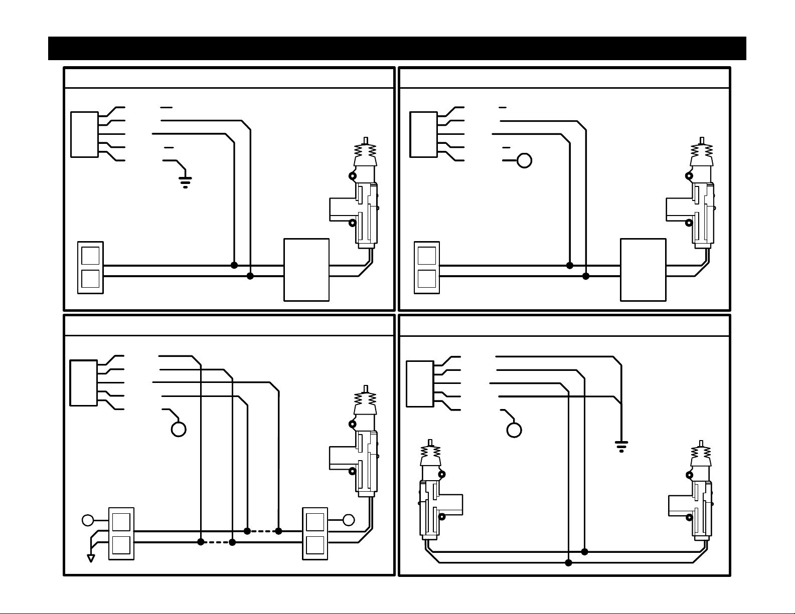
POWER DOOR LOCK WIRING
NEGATIVE TRIGGER DOORLOCK WIRING
WHITE
GREEN
BLUE
BROWN
VIOLET
UL
L
NOT USED
NOT USED
UNLOCK
LOCK
FACTORY
POWER
LOCKING
RELAYS
REVERSE POLARITY DOOR LOCK WIRING
WHITE
GREEN
BLUE
BROWN
VIOLET
POSITIVE TRIGGER DOORLOCK WIRING
WHITE
GREEN
BLUE
BROWN
VIOLET
NOT USED
NOT USED
+
+12V
FUSED
UL
L
UNLOCK
LOCK
FACTORY
POWER
LOCKING
RELAYS
AFTERMARKET MOTOR/DOOR LOCK WIRING
WHITE
GREEN
BLUE
BROWN
VIOLET
+
FUSED
+12V
+
UL
L
CUT
CUT
UL
L
+
+
FUSED
+12V
Page 7
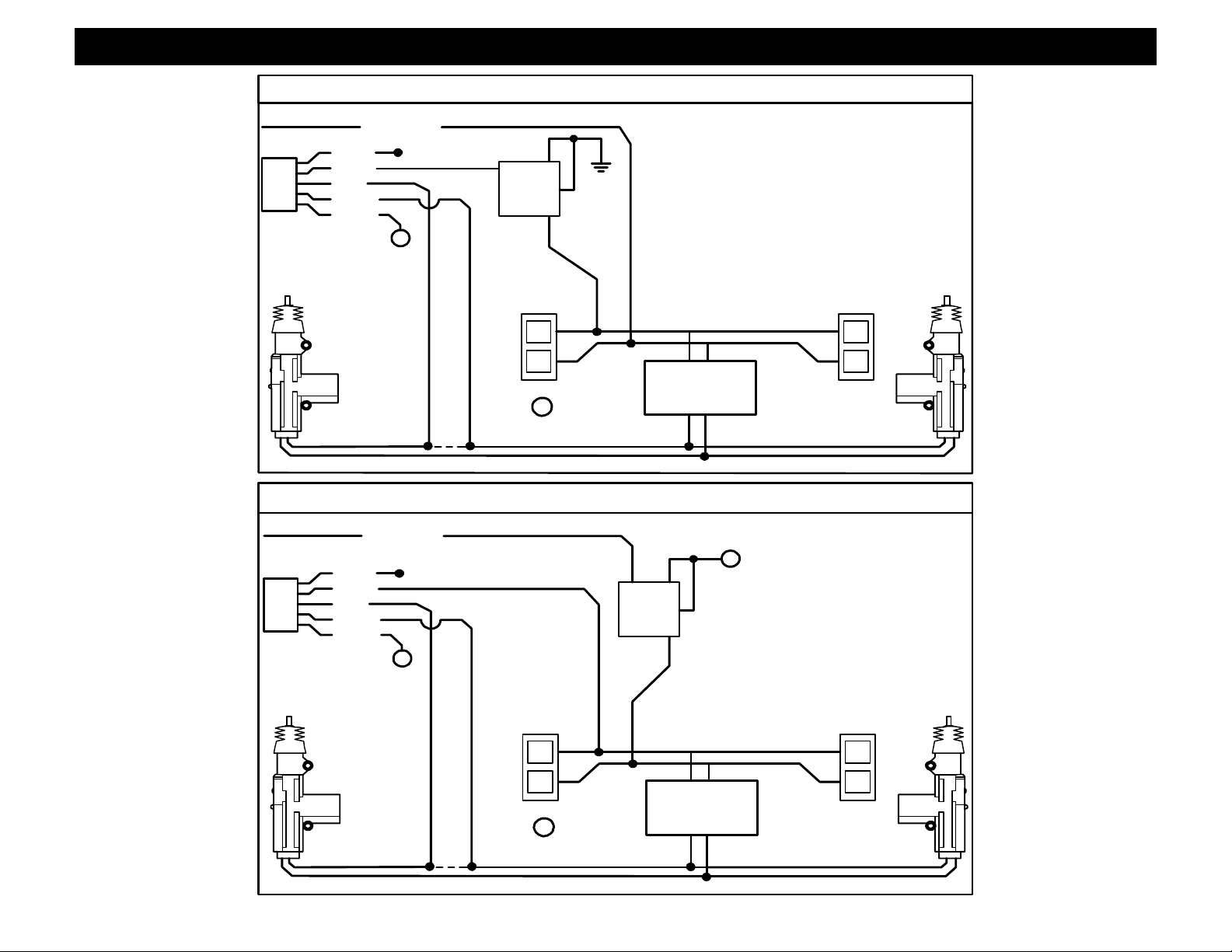
SEPARATE DRIVER’S DOOR UNLOCK WIRING
NEGATIVE TRIGGER DOOR LOCKS
GREEN
WHITE
GREEN
BLUE
BROWN
VIOLET
FUSED
+12V
DRIVER'S
DOOR MOTOR
UNLOCK WIRE CUT
NOT USED
+
85
86
87
3087A
+
+12V
FUSED
FACTORY LOCK
RELAYS
LL
ULUL
GREEN
WHITE
GREEN
BLUE
BROWN
VIOLET
FUSED
+12V
DRIVER'S
DOOR MOTOR
UNLOCK WIRE CUT
NOT USED
+
POSITIVE TRIGGER DOOR LOCKS
FUSED
+
+12V
8685
87
3087A
FACTORY LOCK
+
+12V
FUSED
RELAYS
LL
ULUL
Page 8
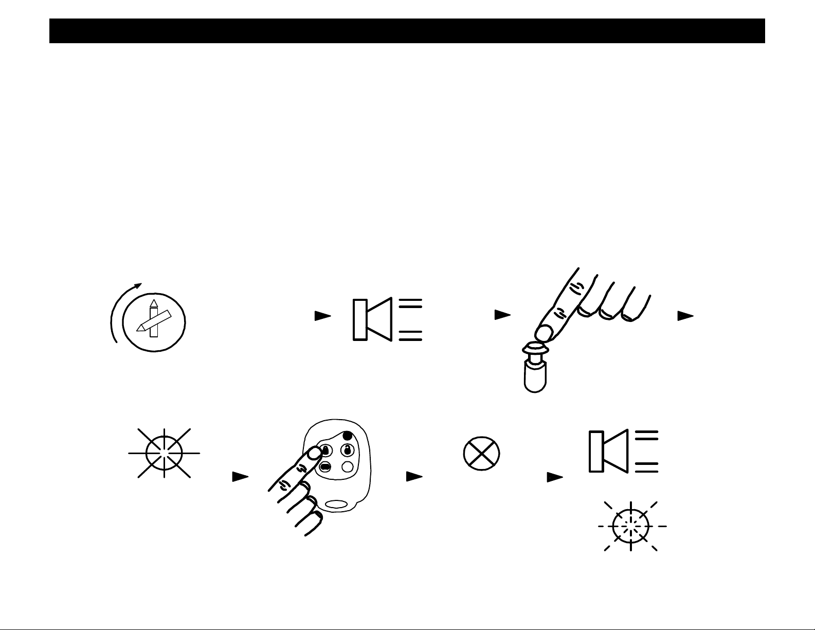
TRANSMITTER PROGRAMMING
1. Turn Ignition ON and OFF 3 times quickly, leaving it ON the 3rd time. (ON/OFF, ON/OFF, ON) You should hear (3)
chirps.
2. Push and release the Program/Override Button 5 times and the Status LED will come on solid.
3. Press #1 (LOCK) on new transmitter two times. LED goes out, siren chirps one time, and LED will flicker for
confirmation.
4. Turn off Ignition.
Note1: Repeat steps 1 through 4 to teach the unit up to 3 transmitter codes Max.
Note 2: You can program button 4 (PANIC) from another vehicle’s CS-2002DC alarm to Arm/Disarm THIS alarm
system by pressing the other vehicles Button#4 two times in step 3. The Other transmitter will only toggle
ARM/DISARM with button 4 and not perform any auxiliary features on THIS system.
DIAGRAM:
IGN
TURN IGN. ON
3 TIMES:
ON, OFF
3 CHIRPS
ON, OFF
PRESS
BUTTON
OFF
ON.
5 TIMES
1 CHIRP
PANIC
LED GOES
STATUS LED
OUT
ON SOLID
PRESS BUTTON
#1 TWO TIMES
LED FLICKER
Page 9
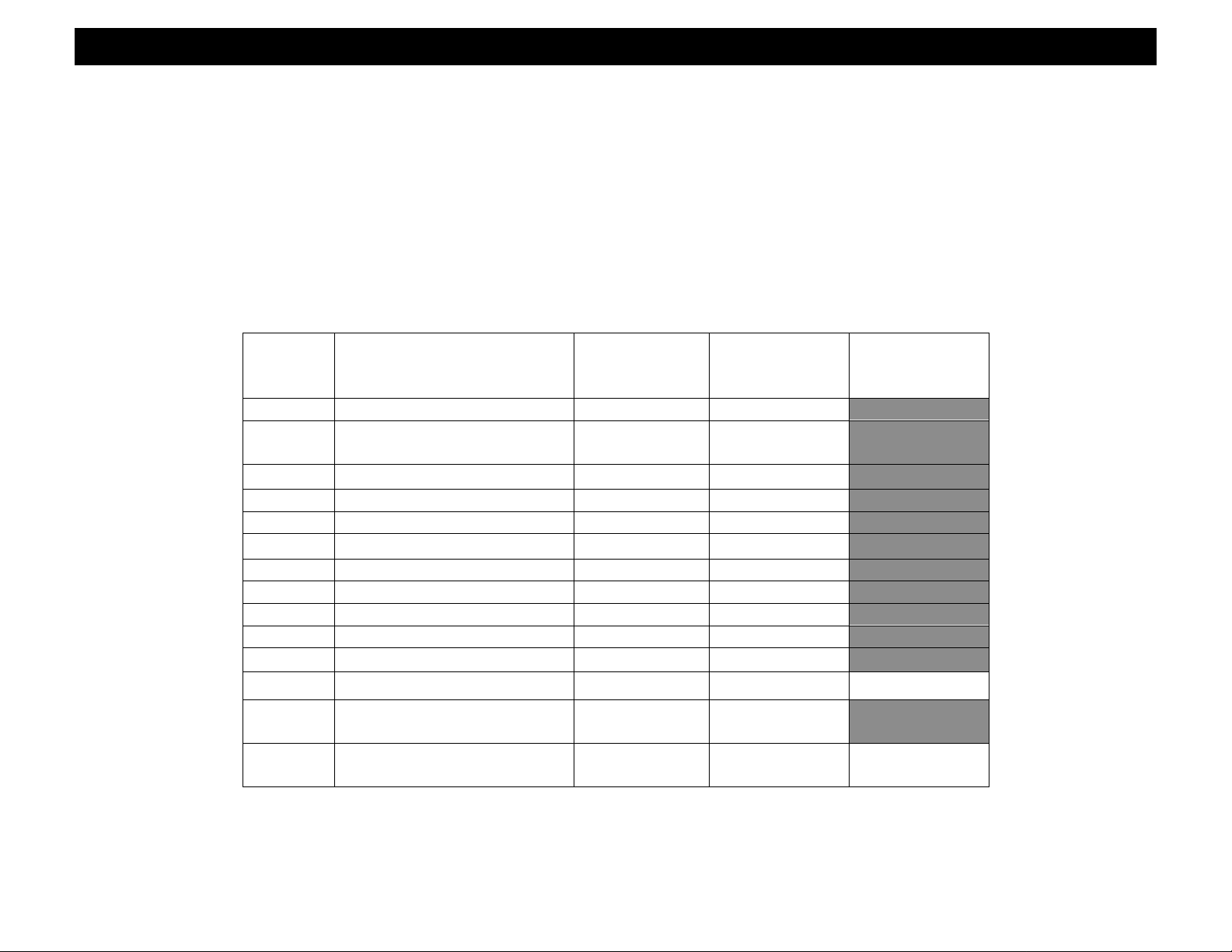
OPTION PROGRAMMING
CS-2003DC PROGRAMMABLE OPTIONS
1. Turn the Ignition ON and press the Override/Program button 5 times. You should hear 6 confirmation chirps.
2. Within the next few seconds, press the Override/Program button [again] the number of times that corresponds to
the feature list below. The siren will chirp for each button press. DO NOT LOSE COUNT!!
3. When you get to the desired option number, press buttons #1, #2, or #3 (Lock, Unlock, Trunk) on the transmitter to
change the option. Button 1 gives a single light flash, Button 2 gives two light flashes, and Button 3 gives three light
flashes. See chart Below for Option descriptions and vales.
4. Change ONE option at a time repeating steps 1-3 as needed. When you are finished customizing options, check
operation to see if the option(s) have changed.
PROGRAMMING OPTIONS CHART
Option # Option Description BUTTON 1
1. Passive Arming ON OFF
2. Quiet Chirp Arm/Disarm
with Button #3
3. Lights on with disarm ON OFF
4. Active Re-Arm ON OFF
5. Silent Arm/Disarm OFF ON
6. Disarm with trunk pop OFF ON
7. Ignition controlled Locks ON OFF
8. Door Lock Pulse Time 0.7 Sec. 3 Sec.
9. Carjack Enable/Disable DISABLE ENABLE
10. Lock with passive arm ON OFF
11. Double Unlock Pulse OFF ON
12. Type of Carjack Protection
LOCK
BUTTON 2
UNLOCK
BUTTON 3
TRUNK
(Default)
ON OFF
ACTIVE PASSIVE FULL-TIME
13. 10/60 Sec. Door Open
10 Sec. 60 Sec.
Warning
14. Horn Chirps OFF Arm/Disarm
Only
Arm/Disarm/
Pre-Warning
1. PASSIVE ARMING
This option controls the Passive (Automatic) Arming feature. If ON, arming will occur 30 Seconds after the ignition is
turned off and the last door has been closed. The LED will begin flashing rapidly while counting down. If a door is
reopened, the system will wait (LED solid) for the door or zone to close before arming. The unit will chirp once and
flash the lights once. Doors will lock if passive locking is selected. Factory default setting is ON.
Page 10

OPTION PROGRAMMING
2. SOFT CHIRP ARM / DISARM WITH BUTTON #3 (SHORT PRESS)
With this feature, the system can be programmed to Arm and Disarm with a very soft siren chirp using a short press on
button #3 on the remote. The Factory Default setting is ON.
3. PARKING LIGHTS ON WITH DISARM
Keeps parking lights on instead of 2 flashes when system is disarmed to assist in locating your vehicle in a crowded
parking lot or structure. Light will stay on for 30 Sec. or until Ignition is turned on. Factory Default setting is ON.
4. ACTIVE RE-ARMING
Active Re-arming allows the system to re-arm itself 30 seconds after disarmed with the transmitter if a door has not
been opened. This is handy if the vehicle is accidentally disarmed (via the Transmitter in your pocket) without you
knowing it. The Factory default setting is ON.
5. SILENT ARMING /DISARMING (NO CHIRPS)
With this feature, the system can be programmed to Arm and Disarm without the siren chirp. Parking lights will be the
only Arm/Disarm confirmation. Pre-Warning does not operate in this mode. The Factory Default setting is OFF.
6. DISARM WITH AUX. OUTPUT 1
Controls whether the system will or will not DISARM when the trunk pop or AUX. feature is used. When the feature is
turned on the unit will DISARM when opening trunk or other AUX feature. Factory Default setting is OFF
7. AUTOLOCK/UNLOCK
Controls whether the doors will automatically lock when the ignition is turned on and will unlock when the ignition is
turned off. Doors will not lock if they are open to prevent locking the keys in. Factory default setting is ON
8. DOOR LOCK/UNLOCK PULSE TIME
Controls the amount of time (0.75 sec. or 3 sec.) for the lock/unlock pulse. The 3 sec. setting may be required for
1980’/90’s European Vehicles that require a long pulse to do Vacuum door lock systems. Factory default is 0.75 sec.
9. CARJACK FEATURES
Enable or Disable Carjack protection features. Factory Default is OFF.
10. PASSIVE LOCKS
This option controls whether the doors will lock when Passive Arming occurs. Note: May increase the risk of locking
keys in the vehicle. Factory default setting is ON.
11. DOUBLE UNLOCK PULSE
The unit will send 2 unlock pulses when the #2 Unlock button is pressed. This feature may be required for interfacing
this alarm with an existing Factory Keyless Entry or Alarm system in a vehicle. These systems are found on some
Nissan, VW, Toyota, and Lexus vehicles. Factory Default setting is OFF.
Page 11

OPTION PROGRAMMING
12. ACTIVE or PASSIVE CARJACK PROTECTION
This feature controls the alarm system’s Carjack Mode for ACTIVE OR PASSIVE protection. Option number 9 Must be
enabled to allow Carjack functions to operate. See Operation section for Carjack Features. Factory default is Active.
13. 10/60 Sec. DOOR/ZONE OPEN WARNING
This setting changes the delay time in which the alarm system begins to monitor the Door, Hood, or Trunk Zones. This
is helpful on vehicles with a delayed dome light to prevent the alarm from giving warning chirps due to the vehicle’s
dome light staying on. Factory Default setting is 10 Sec.
14. HORN CHIRP W/ARM-DISARM
This option controls whether the alarm chirps the Factory car horn for ARM/DISARM if the optional car horn feature is
installed.
OPERATION
4 BUTTON REMOTE TRANSMITTER:
#1
ARM
(LOCK)
PANIC
#3
TRUNK
POP
#2
DISARM
(UNLOCK)
#4
REMOTE
PANIC
ACTIVE ARMING
To arm the alarm and lock the doors, press the #1 (Lock Symbol) button on the transmitter. You will hear a single
siren chirp and the lights will flash once. The system will arm, the doors will lock and the starter will be disabled if these
optional features are installed. The red LED in the vehicle will start flashing after 15 seconds. After a short delay to
allow vehicle and electronics to stabilize the system will be completely armed.
ALARM TRIGGERING
If there is an intrusion into the vehicle or hard impact to the body will sound the alarm and flash the lights for 45
seconds. After 45 seconds the system will automatically shut off and re-arm to continue to protect the vehicle. If a
door is left open then the unit will cycle a second time and continue to protect the other un-tampered zones.
Page 12

OPERATION
DISARMING
To disarm the alarm and unlock the doors, press the #2 (Unlock Symbol) button on the transmitter. You will hear 2
siren chirps and the lights will flash twice. The dome light turns on and the dash LED stops flashing.
ARMED TRIP RESET
If and when the alarm system is tripped, you can reset the unit’s tripped condition without having to disarm and rearm
by pressing the #1 (Lock Symbol) button on the transmitter. The system will reset the siren, lights, AND stay armed.
TRUNK/HATCH POP (REMOTE AUX. OUTPUT 1, OPTIONAL)
To pop the trunk (if optional feature is installed), press Button #3 (Trunk Symbol) on the transmitter for at least 1 ½
seconds. If the system is armed, pressing Button #3 may or may not trip the alarm system when opening the trunk
depending on programming option (3) configuration. See page 9.
REMOTE PANIC PROTECTION
To sound the alarm upon command (panic), press and hold the Button #4 (Panic) for at least 2 seconds until the siren
sounds. Press Button #2 (Unlock) to reset panic mode.
ARMING WITHOUT SHOCK SENSOR/TRIGGER ZONES
To arm the alarm without Shock sensor protection, press button #1 as normal then press Button #4 (Panic) within 2
seconds. You will hear an extra siren chirp indicating shock sensor bypass. To arm the system without ALL trigger
zones press button #1 as normal then press Button #3 (Trunk) within 2 seconds. Again you will hear an extra siren
chirp indicating ALL zone bypass.
PRE-WARNING SHOCK PROTECTION
If a low-level shock to the vehicle body is detected, the pre-warning sensor activates sounding 6 quick siren chirps and
1 light flash. Adjust the shock sensor as needed by turning the control knob clockwise to increase sensitivity and
counter-clockwise to decrease sensitivity.
EMERGENCY OVERRIDE/DISARM
If you have lost the transmitter or it stops working for any reason and the Alarm is armed, you will have to open the
door with the key, which will activate the alarm. Turn the ignition on and press the override/program button about 2
seconds. The Alarm will disarm and enter the Valet mode that allows you to use the vehicle until you can
repair/replace the remote transmitter at which time you can take the vehicle out of valet.
VALET MODE
To disable the Alarm system for vehicle service or otherwise, turn the ignition on and press the override/program
button until the dash LED turns on solid (about 5 seconds) and you hear (1) siren chirp. Repeat the process to exit
VALET mode and the system will chirp (2) times and the LED will turn off. Lock/Unlock and AUX features will still
operate in when in VALET mode.
Page 13

OPERATION
SOFT CHIRP ARM/DISARM
This system can be armed and disarmed with very faint/soft chirps as needed. Press and quickly release Button #3
(Trunk pop) to Arm and Disarm system with soft chirps. Note: If Button #3 is pressed too long, then the Aux. 1 output
will activate.
SILENT ARM/DISARM MODE
The system can be silently armed and disarmed as normal with Lock/Unlock Buttons but no siren chirp. See alarm
programming option (5) to enable or disable this feature. Pre-Warn feature does not operate in this mode.
PASSIVE ARMING / PASSIVE LOCK MODES
If programmed, passive (Automatic) Arming will occur 30 Seconds after the ignition is turned off and the last door has
been closed. The LED will begin flashing rapidly while counting down. If a door is reopened, the system will wait (LED
solid) for the door or zone to close before arming. The unit will chirp once and flash the lights once. Doors will lock if
passive locking is selected. May qualify for insurance discounts-check with your agent or proprietor.
PRIOR INTRUSION ALERT
If the system was tripped in your absence, the dash LED will be flashing rapidly. When the system is disarmed you will
hear 3 chirps (and 3 light flashes). Carefully inspect your vehicle to see if there is any damage or a theft has occurred.
DOME LIGHT ILLUMINATION (OPTIONAL)
This feature turns on the vehicles dome light upon disarm for 30 seconds or until the key is inserted and turned on.
This will provide illuminated entry to your vehicle at night or in dimly lit areas for safety and security.
DEFECTIVE ZONE ALERT/BYPASS
If the system detects a faulty or open zone (Door left open) when the system is ACTIVELY ARMED, the siren will chirp
4 times along with 4 light flashes. The faulty zone will be automatically bypassed.
AUTOLOCK/UNLOCK
The doors will automatically lock when the ignition is turned on and will unlock when the ignition is turned off. Doors
will not lock if they are open to prevent locking the keys in.
ACTIVE RE-ARMING (FAIL-SAFE PROTECTION)
Active Re-arming means that the system will re-arm itself 30 seconds after disarmed with the transmitter if a door has
not yet been opened. This is handy if the vehicle is accidentally disarmed (via the transmitter in your pocket) without
you knowing it. This feature can also be turned off in programming option (4).
Page 14

OPERATION
2nd AUX. OUTPUT (REMOTE AUX. OUTPUT 2)
To activate the Second auxiliary output press Button #1 (Lock) and hold for more than (1) second. This output can be
used to control other optional add-on accessories such as Remote Engine Start Modules, Window Roll up/down
modules, etc.
2 VEHICLE CONTROL
This unit can be programmed to Arm/Disarm a second vehicle with a CS-2002DC system installed. Follow the steps
for transmitter programming on a second vehicle using Button #4 (Panic) from the existing remote. This will provide
arm/disarm control of a second vehicle with the same transmitter using button#4.
CARJACK PROTECTION
ACTIVE CARJACK
This feature provides Active Carjack protection and must be enabled before use through Alarm programming options
(9) & (12) See page 9. When the Ignition is on (vehicle is running), press button #4 (Panic) for more than 1 Sec.
Parking lights will flash to confirm the Carjack countdown sequence. 90 Seconds later, the unit will begin a Carjack
Cycle consisting of 15 seconds of pre-warning chirps turning into a full system activation with siren/flashing light pulses
for up to 5 min. To reset Active Carjack, press and Hold Button #4.
PASSIVE CARJACK
This feature provides Passive Carjack protection and must be enabled before use through Alarm programming options
(9) & (12). See page 9. We recommend this mode should only be used in serious situations. When the Ignition is on
(vehicle is running), if a door is opened the Carjack countdown sequence will be initiated. There will be 2 light flashes
for confirmation of countdown. 90 Seconds later, the unit will begin a Carjack Cycle consisting of 15 seconds of prewarning chirps turning into a full system activation with siren/flashing light pulses for up to 5 min. To reset Passive
Carjack ignition has to be on, then press the override/program button (3) times.
FULL-TIME CARJACK
This feature provides full-time Carjack protection and must be enabled before use through Alarm programming options
(9) & (12). See page 9. EACH TIME the Ignition is turned on, a Carjack countdown sequence will be initiated. 90
Seconds later, the unit will begin a Carjack Cycle consisting of 15 seconds of pre-warning chirps turning into a full
system activation with siren/flashing light pulses for up to 5 min. To reset Full-time Carjack, ignition has to be on,
DOOR MUST BE then press the override/program button (3) times.
Page 15

CS2003DC REVA 2.10.00 Crimestopper Security Products
1770 S. Tapo Street
Simi Valley, CA 93063
Page 16

www.crimestopper.com
 Loading...