

Page 1
Cricket
Robot
Documentation
Revision 1.0B Copyright 2015
Page 2

Contents
CRICKET THE ROBOT ...................................................................................................... 4
Description ....................................................................................................................... 4
Cricket Kit Contents ......................................................................................................... 5
Getting Started ................................................................................................................. 5
Using the Remote Control ................................................................................................ 5
Documentation ................................................................................................................. 7
Software and Download Cable ......................................................................................... 7
Cricket Features ............................................................................................................... 7
Top View .......................................................................................................................... 8
Bottom View ..................................................................................................................... 9
Front View ...................................................................................................................... 10
HOW CRICKET WORKS.................................................................................................. 11
How Does Cricket Walk? ............................................................................................... 11
Obstacle Avoidance ....................................................................................................... 11
Random Noises ............................................................................................................. 11
Flashing LED Eyes ........................................................................................................ 11
Remote Control .............................................................................................................. 11
PLAYING WITH CRICKET ............................................................................................... 12
ABOUT CRICKET’S HARDWARE ................................................................................... 13
Chassis .......................................................................................................................... 13
Legs ............................................................................................................................... 13
Servo Motors .................................................................................................................. 13
Arduino Controller .......................................................................................................... 14
Batteries ......................................................................................................................... 15
Speaker and Sound Generation ..................................................................................... 15
Infrared Remote Receive ............................................................................................... 15
Light Emitting Diodes ..................................................................................................... 16
Feeler Wires and Switches ............................................................................................ 16
Programming Connector, Cable and Software ............................................................... 17
Uploading an Arduino Program ...................................................................................... 18
Launch the Arduino Application ..................................................................................... 19
Open the blink Example ................................................................................................. 19
Select your Board .......................................................................................................... 19
Select your serial port .................................................................................................... 20
Upload the program ....................................................................................................... 20
2 – Cricket Robot Documentation
Page 3

ASSEMBLING CRICKET’S ARDUINO CONTROLLER BOARD .................................... 22
Tools Needed ................................................................................................................. 22
Parts Layout ................................................................................................................... 24
Installing the Parts ......................................................................................................... 25
Checkout and Cleanup................................................................................................... 32
ASSEMBLING CRICKET’S CHASSIS ............................................................................. 33
Tools Needed ................................................................................................................. 33
General Assembly Instructions ...................................................................................... 34
Assemble the Legs ........................................................................................................ 34
Assemble the Center Leg Beam .................................................................................... 36
Attaching the Servo Motor Mounts ................................................................................. 40
Install the PC Board Mounts .......................................................................................... 42
Assemble the Leg Control Arms .................................................................................... 46
Assemble the Sonar Bracket .......................................................................................... 47
ABS Parts of Chassis are Now Complete ...................................................................... 51
Installing the Servos into the Chassis ............................................................................ 52
Installing Cricket’s Legs ................................................................................................. 54
Installing the Leg Control Arms ...................................................................................... 58
Installing the Battery Holder ........................................................................................... 62
Installing the Speaker .................................................................................................... 64
Completing the Feelers .................................................................................................. 65
Installing the Feelers ...................................................................................................... 66
Centering the Servos ..................................................................................................... 72
Installing the Servo Horns .............................................................................................. 72
Installing the Sonar Module ............................................................................................ 78
Cleaning Up the Wiring .................................................................................................. 81
Final Checkout ............................................................................................................... 84
TROUBLESHOOTING ..................................................................................................... 88
APPENDIX A – SCHEMATICS ........................................................................................ 90
APPENDIX B - PARTS LIST ............................................................................................ 92
APPENDIX C - PC BOARD LAYOUT .............................................................................. 93
3 – Cricket Robot Documentation
Page 4
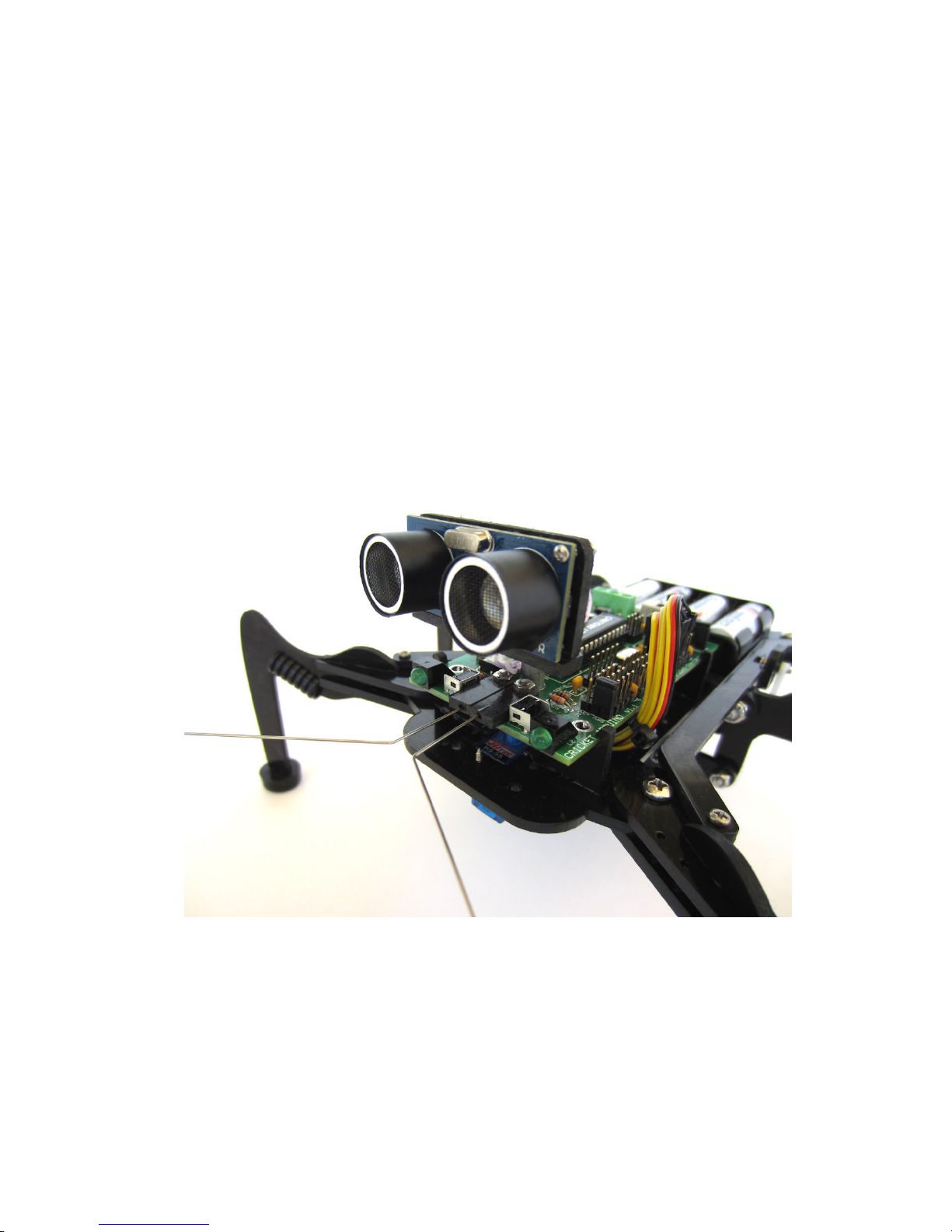
Cricket the Robot
Congratulations on the purchase of your Cricket Robot Kit. Cricket is a unique walking
robot. You will find that he is also a powerful programmable robot.
Cricket has:
Arduino based
Programmable Controller
Sturdy Laser Cut Body
construction
3 Hitec Servos to control six
legs
Sonar with Hitec scan servo
2 LED Eyes for visual
effects
Speaker to make sound
effects
2 Bump Feelers
IR Remote Control
Documentation
Cricket comes preprogrammed and ready to go. As you become more familiar with his
capabilities you can easily modify his control program to add or change his behaviors.
Programming Cricket requires just the standard Arduino Environment and a USB down
load cable.
Description
Cricket is a six-legged walking robot. He uses three motors to make the six legs walk in a
tri-gate fashion. Tri-gate means that Cricket has three legs on the ground at any one time.
The three legs touching the ground form a triangle which is very stable. Cricket can walk
forward, backward, and turn right and left. Cricket can also make sounds, flash his LED
eyes, and detect obstacles with his sonar and feelers. The Arduino Uno compatible
controller operates all of Cricket’s capabilities. The controller can be easily programmed
using the standard Arduino environment. The Arduino libraries allow you to perform
things like making sounds, blinking lights, and controlling motors. The Arduino based
program is written on a PC and then is downloaded through the PC’s USB port.
4 – Cricket Robot Documentation
Page 5
Cricket Kit Contents
Cricket robots come in three variations. They are:
Fully assembled robot
Robot kit with fully assembled Arduino controller
Robot kit with Arduino controller as a kit for user assembly
If you received an assembled robot, you may review the assembly instructions if you
would like to become more familiar with how your robot is assembled. Otherwise just start
enjoying playing with your Cricket Robot
Getting Started
Cricket runs on 4 standard AA batteries. You may use rechargeable batteries or alkaline
batteries. Install the batteries while noting the correct orientation. Place Cricket on a level
service and push the slide switch at the back end of the controller board. Cricket will make
a series of chirping sounds, bring all his legs into a neutral position, pause for one second
and then begin walking. While walking around, Cricket will make chirping sounds at
random times, and he will blink his LED eyes. He will also make a series of sounds
whenever his antennae touch an object or when the sonar detects something. When
Cricket detects an obstacle, he will back up and then turn away from the obstruction and
keep wandering around. Cricket will continue to walk around until his battery becomes
weak. You can tell the battery is weak when the robot starts to act erratically. Replacing or
charging the batteries for a few hours will restore Cricket’s health.
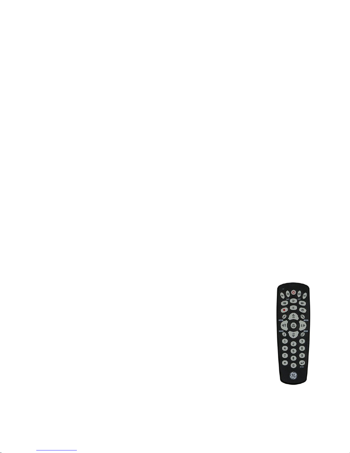
Using the Remote Control
In addition to Cricket’s ability to wander around on his own, he will also respond to his
remote control. The remote is simply a Universal remote setup as a Sony TV/VCR
Combo. You may use your own remote or the one provided with Cricket.
The remote control will override whatever Cricket is doing and execute the following
actions:
Volume Up Cricket turns right.
Volume Down Cricket turns left
Channel Up Cricket moves forward at a fast walk
Channel Down Cricket backs up
Rewind Shake Left Legs
Fast Forward Shake Right Legs
Play Rock Back and Forth
Stop Cricket stops and holds his position
Pause Cricket freezes as long as button is held
Keys 0-9 Cricket makes different interesting sounds
Mute, On-Off Stop and center legs
Prev. CH, Record Dances the Cha-Cha
The sound keys 0-9 are fun to play with because Cricket can make a continuous stream of
various sounds and chirps while you hold one of these keys down. Pushing the Pause
button will cause Cricket to freeze for as long as you hold the button. Pushing Stop
Remote Control
5 – Cricket Robot Documentation
Page 6
causes Cricket to stop and hold his last position. Mute which is in the center of the round
volume and channel area causes Cricket to stop and center his legs.
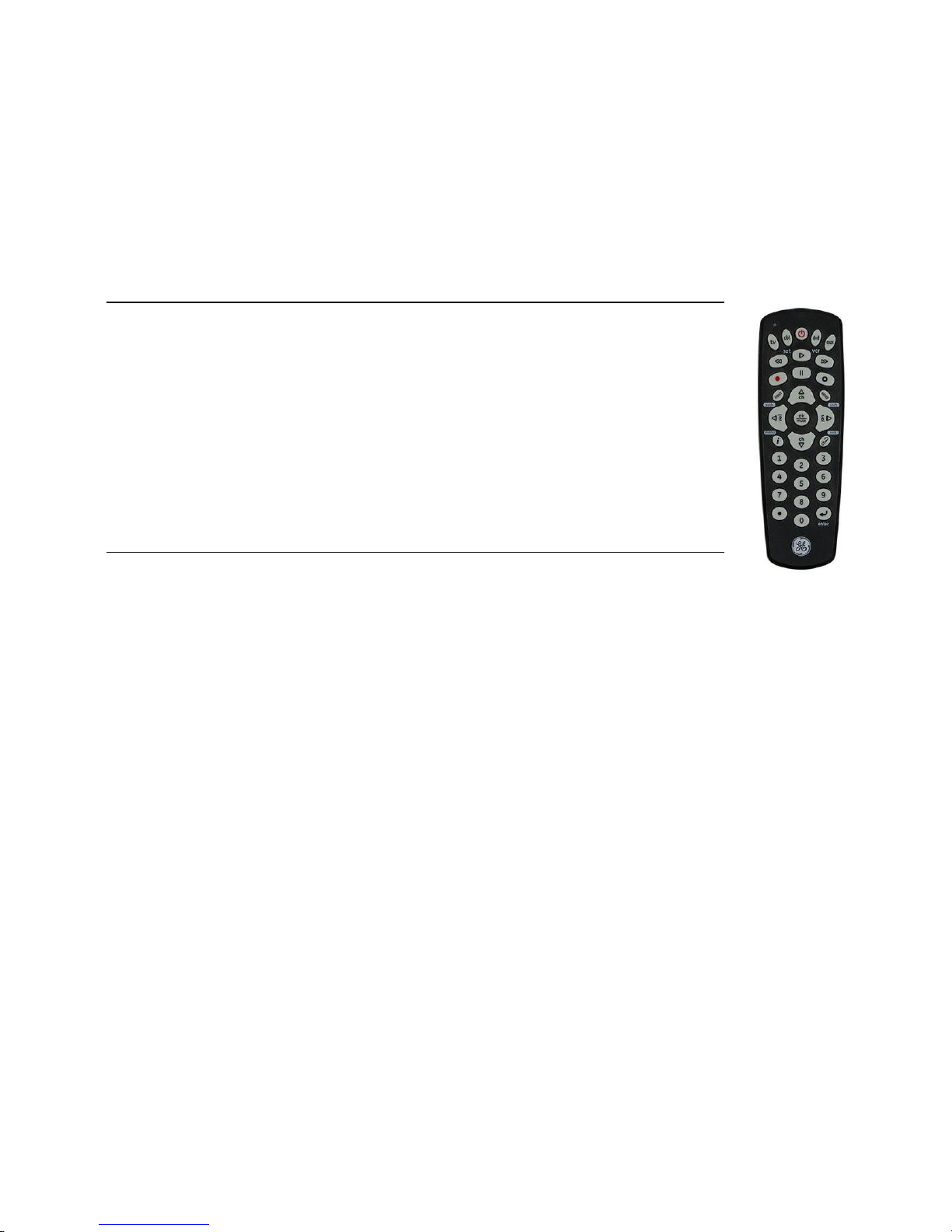
IMPORTANT: If the remote fails to work, you may need to reset the remote operation
code. Use the following instructions for your remote. These instructions are also on the
battery door of your remote. If you have an older remote, the code may be different but
the instructions are the same.
The code is 0972 for GE 4 Device Remote (24993) as shown to the right.
To Reprogram for CRICKET:
Press and release the TV button.
Press and hold the setup button until the LED lights.
Then key in the three-digit code 0972 and the red LED will go out.
6 – Cricket Robot Documentation
Page 7

Documentation
This documentation includes information on using Cricket and how to assemble a Cricket.
This manual and assembly information and will be updated periodically.
Software and Download Cable
Some Cricket kits come with an optional USB/Serial programming cable. This cable can
be used to program the Arduino with the original Cricket software or to program Cricket
with your own custom version of the software. If you did not get a cable, you can purchase
SparkFun part number DEV-9716 or any similar 6 pin Arduino programming module.
https://www.sparkfun.com/products/9716
The Cricket program can be edited in the Arduino environment and the Arduino
reprogrammed. A new program will erase the current program. The original Cricket
program may be downloaded to restore Cricket’s original behavior.
Cricket may also be purchased with a Nano Arduino Module which can also be connected
to a USB port so that Cricket may be reprogrammed. Both the Arduino IC and the Nano
Module use the same control Sketch.
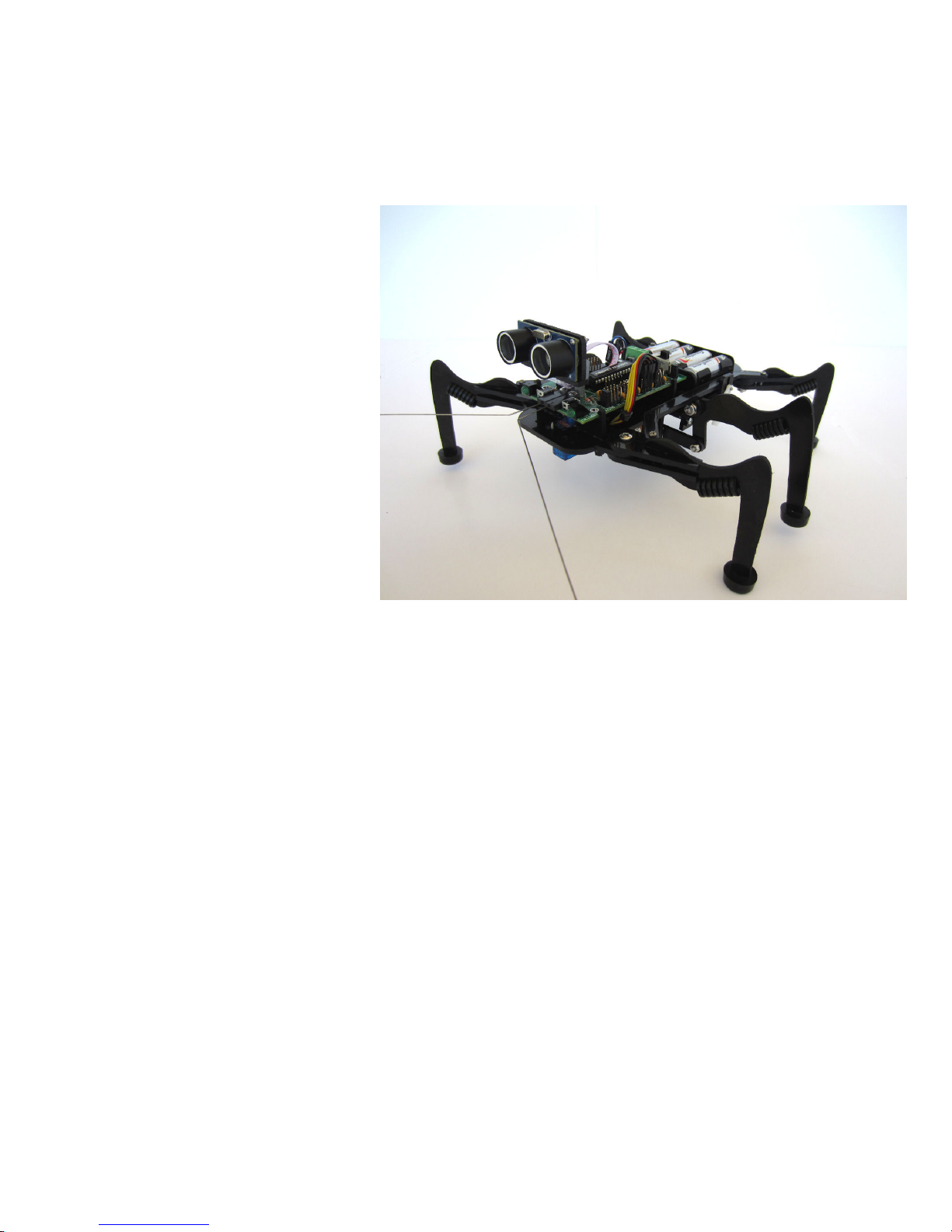
Cricket Features
The following photos show the layout of Cricket’s features including top, bottom, and front
views of the robot.
7 – Cricket Robot Documentation
Page 8
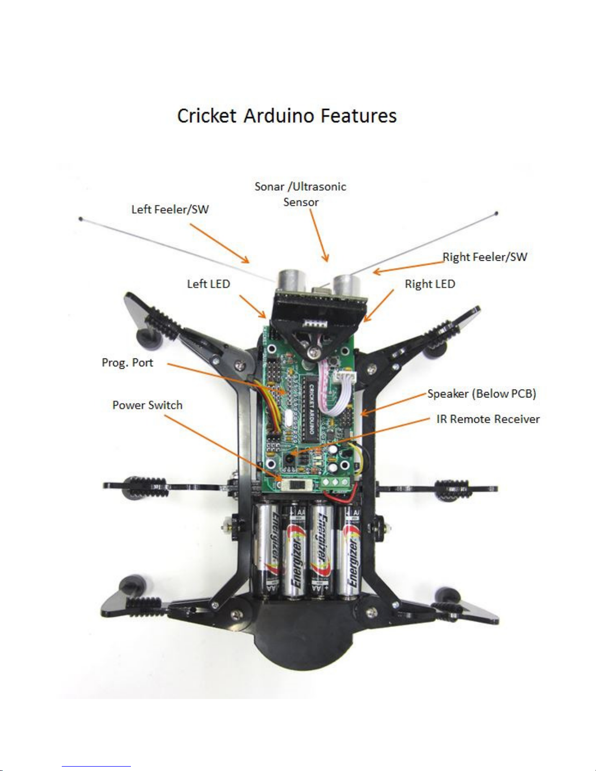
Top View
8 – Cricket Robot Documentation
Page 9
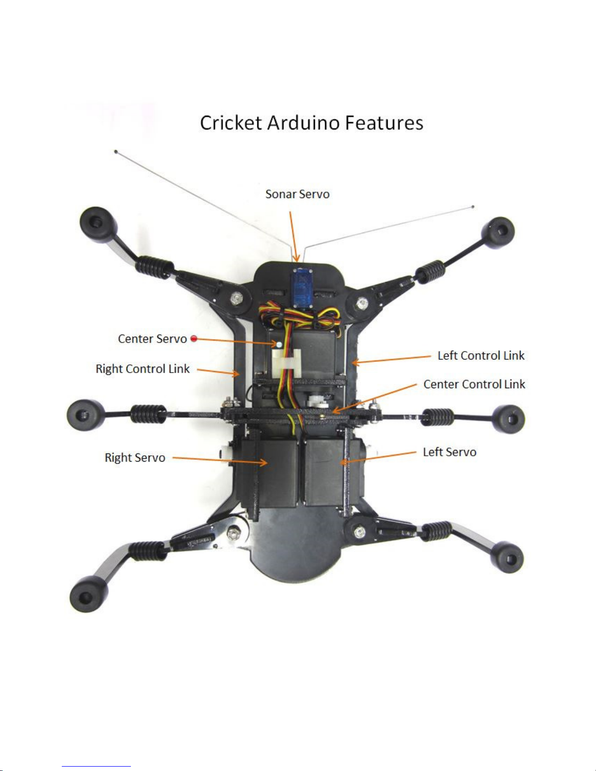
Bottom View
9 – Cricket Robot Documentation
Page 10
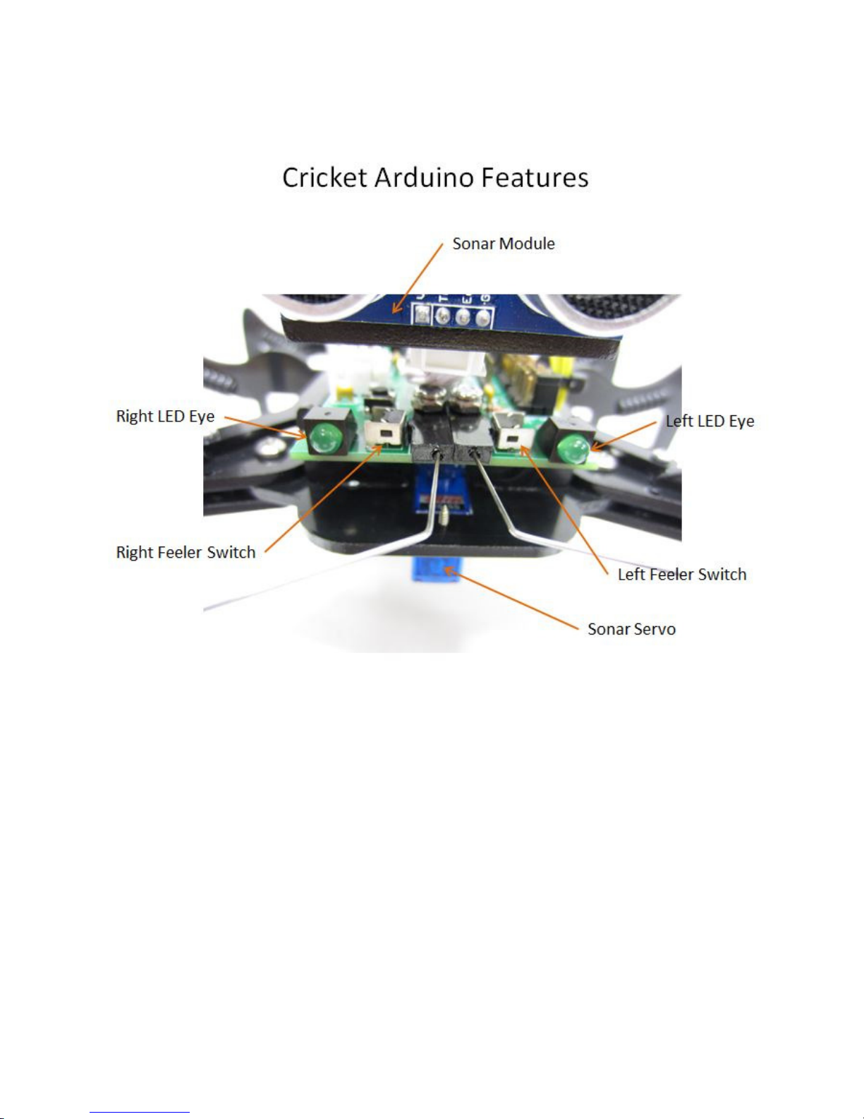
Front View
10 – Cricket Robot Documentation
Page 11

How Cricket Works
The following paragraphs explain how Cricket is able to walk, make sounds, and how his
various behaviors and features work.
How Does Cricket Walk?
Cricket uses what is called a tri-gate walk. Tri-gate walking is one of the most efficient
ways to implement a walking robot with a minimum number of motors. The right and left
servo motors move the right and left pairs of legs forward and backward. In order for this
leg movement to move the robot forward, the center legs rock the robot to one side so the
legs can move forward without touching the ground. When the legs are touching the
ground a backward movement pulls the robot forward one step. This stepping alternates
from one side to the other causing the robot to walk forward. Walking backward is the
same as forward except that the legs are off the ground when being moved backward and
touching the ground when being pulled forward. Watch the robot for a while and you will
begin to see how it works. Cricket executes a turn by stepping forward with one side
while the other side steps backwards.
Obstacle Avoidance
Cricket’s Arduino microcontroller is constantly monitoring his sonar and his feeler switches
to detect obstacles. When Cricket detects an object with his sonar or his feelers, he stops,
makes a noise, backs up three steps, scans the area in front of him for the best direction,
and then continues moving forward in the best direction. If either the feelers are bumped,
Cricket will also do a sonar survey of what is in front of him and select the best direction to
proceed. The best direction is the longest unobstructed distance he can measure.
Random Noises
You may notice that Cricket chirps from time to time but not always. Sometimes he will
chirp three or four times in a row. This random chirping is part of the Arduino program.
For every step the robot takes he looks up a random number. If the number is less than a
preset value, Cricket stays quiet, but if the number is larger than a preset value, Cricket
makes a chirp sound.
Flashing LED Eyes
Cricket has two LED eyes. After Cricket is powered up, the green LED eyes will light and
randomly turn on and off. These LEDs are all under the program control and are not just
blinking on their own. Cricket’s eyes will alternate turning on when he is sleeping. Try
pushing the mute button.
Remote Control
The square black module on the controller board is a TV remote receiver module, which
responds to the Remote Control by directing Cricket to actions other than his normal
automatic behavior. During each step Cricket takes, he also checks to see if any remote
control commands were received. The remote module receives the remote control signal
and the Arduino turns the information into commands which Cricket can use to perform
actions. Cricket is able to understand almost all of the keys on the remote.
11 – Cricket Robot Documentation
Page 12

Playing with Cricket
So that is enough of the details. Here’s what you can do with Cricket!
Put Cricket in an area with some obstacles and watch how he walks around them
detecting things in his way. Are there things that he doesn’t see? What would he
need to see things he currently misses
Use the Cha-Cha and side leg movements to choreograph a dance routine using
Cricket’s remote control. Here’s an example of the “Harlem Shake”
https://www.youtube.com/watch?v=9qCdq174cd8
And another one:
https://www.youtube.com/watch?v=L3Fsne3_BPk
Using the remote control, steer Cricket through an obstacle course.
Try the programming experiments in the manual “Cricket Programming”
After you tried the above, think about ways that you would improve your Cricket.
You could change the sounds, add unique leg movements that are different than
the Cha-Cha, or add crazy random behaviors to the things he does.
How would you make Cricket walk around a table without falling off?
Improve or modify Cricket and enter him in a Science Fair or County Fair. We have
already seen kids do this and win first place ribbons.
Cricket is a great way to learn new programming and robotic skills. Playing with him will
trigger ideas of how he could be made better. Using the Arduino environment and possibly
some other sensors, will allow you to make him even smarter.
12 – Cricket Robot Documentation
Page 13
About Cricket’s Hardware
The following paragraphs explain
each of Cricket’s components.
Chassis
The Cricket body is made from laser
cut ABS plastic. Motors, controller,
switches, and the battery pack are all
mounted on this chassis. This
chassis is strong and easy to
assemble.
Legs
Cricket’s legs are also made from
laser cut ABS plastic. The legs pivot on
a simple screw and a captive nut. The
legs have control arms that transfer the
rotary motion of the servos into linear
forward and backward motion or up and
down motion. Cricket’s foot pads are
made from rubber bumpers which are
attached to the end of the leg.
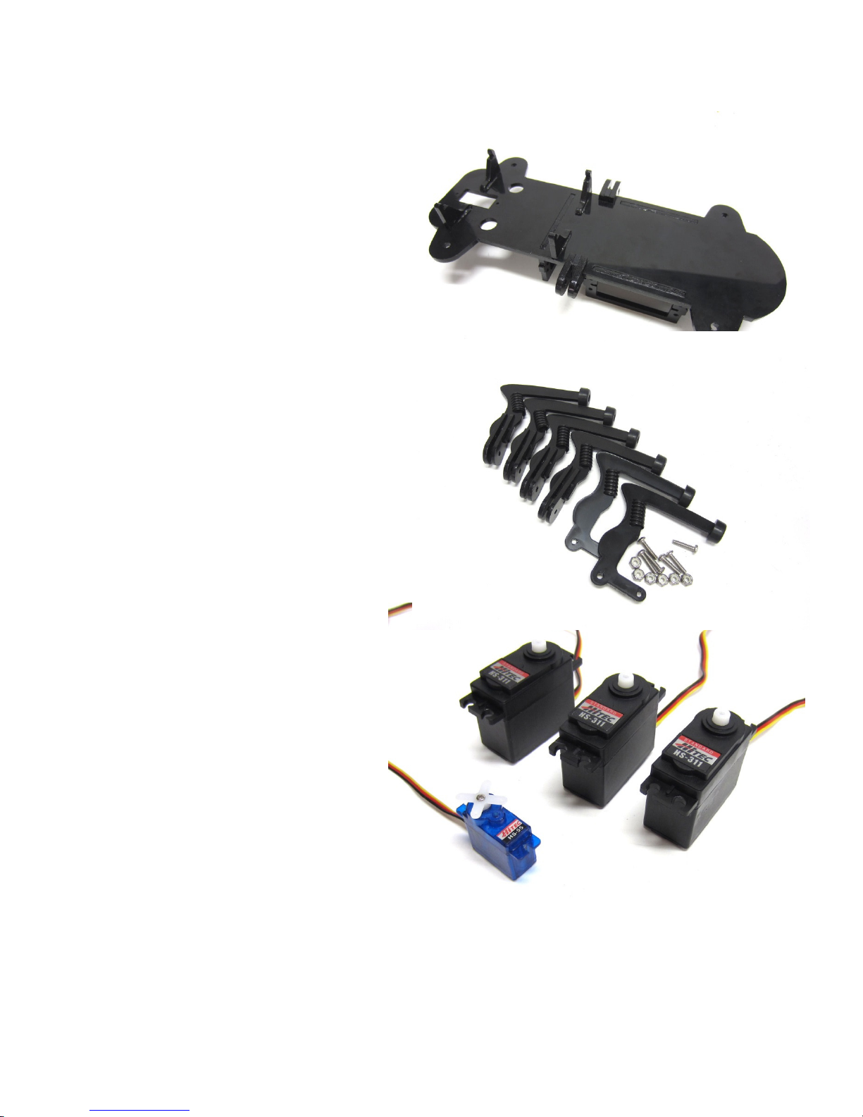
Servo Motors
Cricket uses three servo motors for
walking and one for the Sonar.
These motors are hobby servo
motors used for model airplanes and
cars. Each motor has three wires that
supply 6 volts (red), ground (black),
and the special controller signal
(yellow). The controller signal is a
special stream of pulses supplied by
the Arduino controller. These pulses
tell the motor what position to go to.
Normally a radio control receiver in a
model airplane or car would supply
this special signal but for Cricket, the
Arduino microcontroller generates
these signals. The motor on the
right side moves the right front and rear legs forwards and backwards. The motor on the
left side moves the left front and rear legs forwards and backwards. The center motor
pulls on the right and left center legs to make the robot lean from one side to the other.
The small blue motor runs the Sonar Sensor.
13 – Cricket Robot Documentation
Page 14
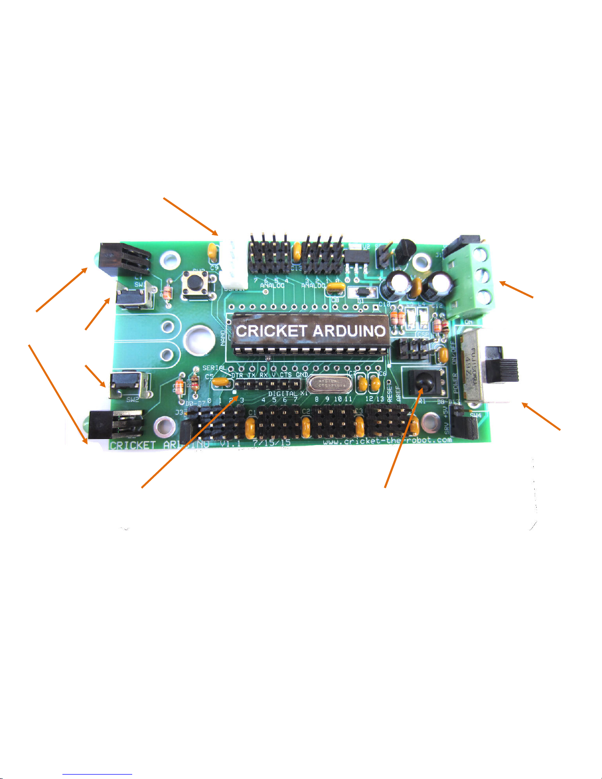
Arduino Controller
The Arduino microcontroller is mounted on a small circuit board along with the connectors
that go to the motors, feeler switches, and batteries. A download 1/8” phono connector on
the front left of the circuit board allows the Basic programs to be downloaded into the
Arduino. There is a small speaker for sounds and LEDs that can be blinked. The battery
pack powers the Arduino directly while a 5-volt regulator supplies power for the Arduino.
LED Eyes
Sonar Conn.
Analog Sensor
Connectors
Power
connector
Feeler
Switches
(pin 1 is leftmost pin)
Digital & Servo
Motor Connectors
Remote Sensor Programming Port
Power
Switch
14 – Cricket Robot Documentation
Page 15
Batteries
Cricket uses standard AA batteries. The batteries will last about 1 -2 hours of operation
before needing to be replaced. Rechargeable batteries are an economical alternative to
alkaline cells. Battery power enters the controller board through a terminal block at the
rear of the controller. The on-off switch at the rear of the controller turns Cricket on and
off.
Speaker and Sound Generation
The Arduino microcontroller has the ability to
make sounds of various frequencies and
duration. The Cricket program makes
extensive use of this ability using a small
speaker to generate many different sound
effects. I would be an interesting experiment to
modify some of the “Sound” commands in the
Cricket program and see how it affects
Cricket’s voice. The speaker is glued to the
chassis face down which may seem odd but
the chassis acts as a sound board much like
the body of a guitar. If you follow the directions
you will be surprised how loud the Cricket sounds are.
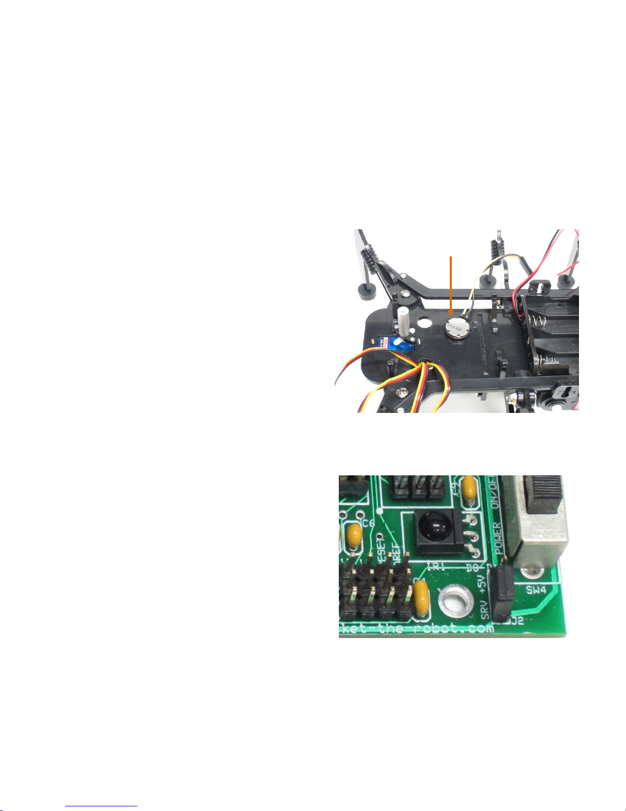
Infrared Remote Receive
The remote control uses infrared light to
communicate with Cricket. The black part with a
bubble on the controller board (IR1) is an IR
receiver, which can detect the remote control
signals. The detected signal is converted into a
command which the program software uses to
override Crickets autonomous behavior.
Speaker
15 – Cricket Robot Documentation
Page 16
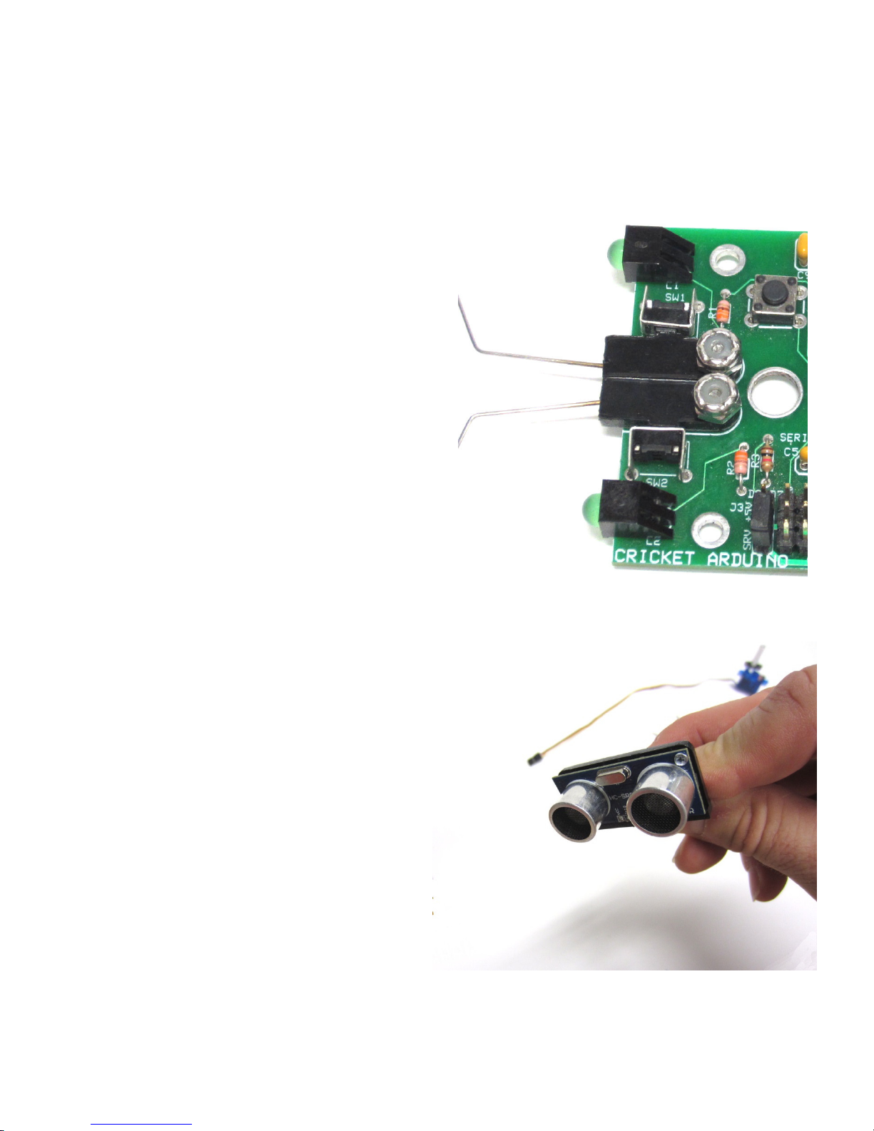
Light Emitting Diodes
Two green LEDs give Cricket the appearance of having eyes. These LEDs blink on and
off under program control. They may be controlled individually.
Feeler Wires and Switches
Once Cricket starts walking around, it doesn't
take long before he will run into something.
Without a way to detect an obstacle he would
get stuck. For this reason, Cricket has long
feelers much like a real cricket has. These
feelers are connected to small switches,
which turn on, when the feeler is pushed. The
Arduino controller checks the switches and if
they are closed, the robot backs up and turns
away from the obstacle. The feelers are quite
flexible and sensitive.
Sonar Sensor
Cricket has a sonar sensor which rotates
using a small hobby servo. Cricket takes
distance measurements in 7 directions.
These 7 measurements are then
compared to find the most unobstructed
direction for Cricket to head.
16 – Cricket Robot Documentation
Page 17
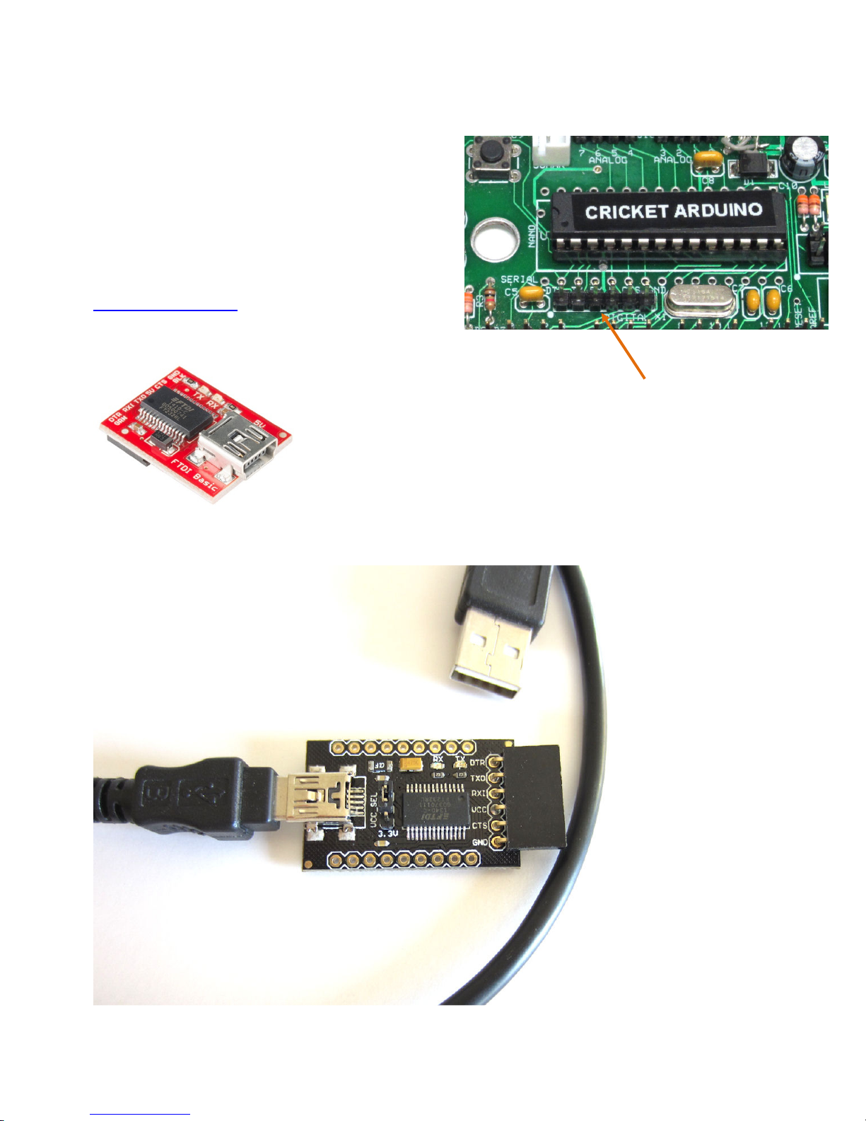
Programming Connector, Cable and Software
Cricket uses an Arduino Uno compatible
controller but this board does not have the USB
circuitry onboard. This was done to save cost.
If you want to program Cricket, you will need to
use a USB/Serial programming module that
plugs into the header just above the Digital I/O.
This module is an Arduino standard, is
inexpensive, and can be purchased from
multiple sources. SparkFun at
www.sparkfun.com carries the modules as part
number DEV-09716 for $14.95.
SparkFun DEV-09716
This module plugs
directly into the Serial
programming header on
the Cricket Controller.
You’ll also need a mini
USB cable.
Serial Program Port
17 – Cricket Robot Documentation
Page 18
Uploading an Arduino Program
This procedure assumes that you have the Arduino software installed. If you don’t,
download the Arduino environment from https://www.arduino.cc/en/Main/Software and
install it using their instructions. The SparkFun USB/Serial module DEV-09716 will be
recognized with the Arduino drivers.
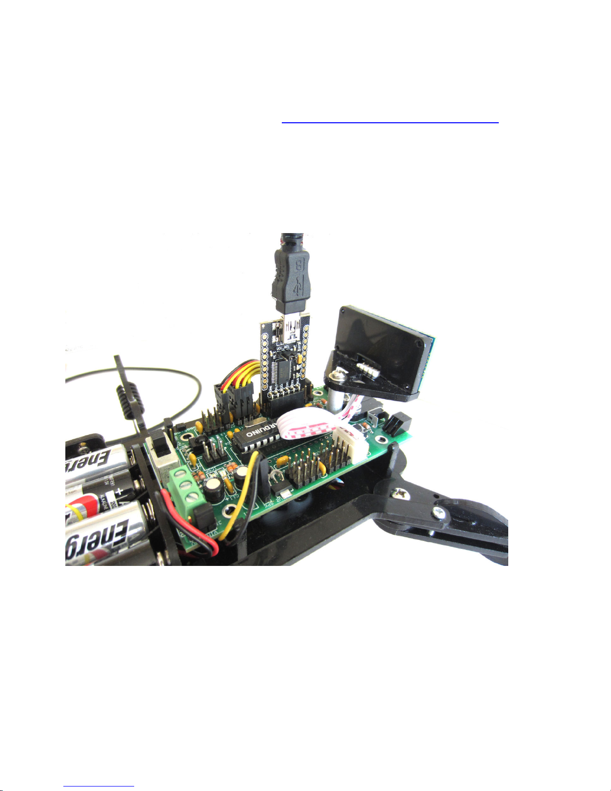
Once you have the Arduino software installed, connect the SparkFun or similar
USB/Serial cable to the Cricket Arduino Controller. Make sure to note pin 1 of the
USB/Serial module and plug it into the Cricket controller with the dot lining up with pin
one.
Cricket with Programming Cable Connected
18 – Cricket Robot Documentation
Page 19
The following instructions are from the Arduino site
https://www.arduino.cc/en/Guide/Windows#toc1
Launch the Arduino Application
Double-click the Arduino application (arduino.exe) you have previously downloaded.
(Note: if the Arduino Software loads in the wrong language, you can change it in the
preferences dialog. See the Arduino Software (IDE) page for details.)
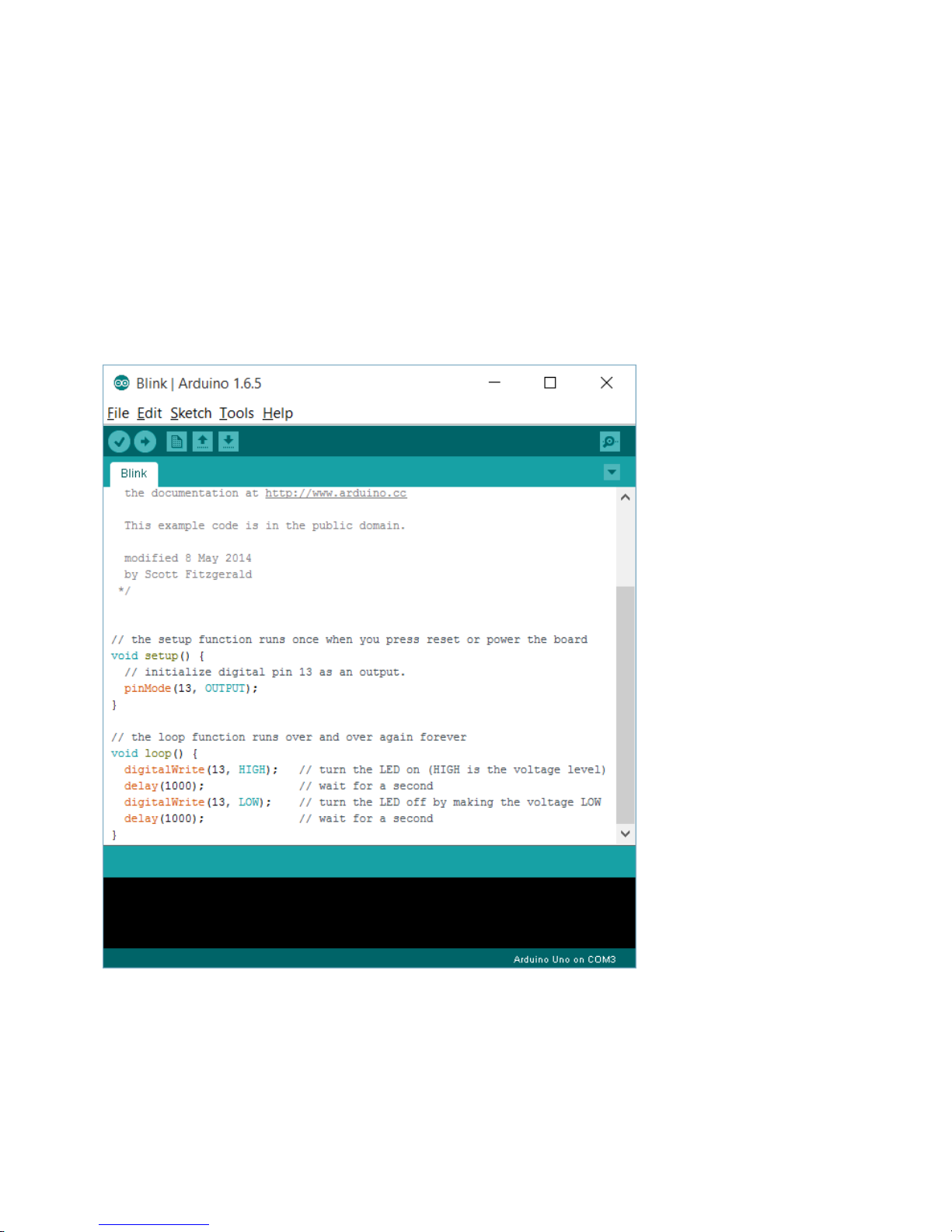
Open the blink Example
Open the LED blink example sketch: File > Examples >01.Basics > Blink.
Select your Board
You'll need to select the entry in the Tools > Board menu that corresponds to your
Arduino. For Cricket the board is “Arduino Uno”
19 – Cricket Robot Documentation
Page 20
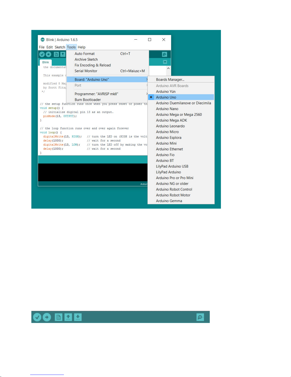
Selecting an Arduino Uno
Select your serial port
Select the serial device of the Arduino board from the Tools | Serial Port menu. This is
likely to be COM3 or higher (COM1 and COM2 are usually reserved for hardware serial
ports). To find out, you can disconnect your Arduino board and re-open the menu; the
entry that disappears should be the Arduino board. Reconnect the board and select that
serial port.
Upload the program
Now, simply click the "Upload" button in the environment. Wait a few seconds - you should
see the RX and TX LEDs on the SparkFun USB/Serial board flashing. If the upload is
successful, the message "Done uploading." will appear in the status bar.
20 – Cricket Robot Documentation
Page 21

A few seconds after the upload finishes, you should see the pin 13 LED on the board start
to blink (in red). If it does, congratulations! You've gotten Cricket Arduino up-and-running.
If you have problems, please see the troubleshooting suggestions.
You have programmed Cricket with a Sketch that only blinks the pin 13 LED. If you would
like to restore Cricket to his full operation, select the Cricket program from your CD under
“Software”. Select “Cricket_Arduino_1_0.ino. Do another download the same way you did
the “blink” download above. After the download, Cricket will straighten his legs and make
a couple of beeps. Your Cricket is now back to its normal operation.
21 – Cricket Robot Documentation
Page 22
Assembling Cricket’s Arduino Controller Board
If you received a Cricket kit with the Arduino Controller board already assembled, please
skip this section.
Assembling Cricket requires that you solder the parts onto the controller board and
assemble the robot chassis. I suggest that you assemble the controller first so you can
center the motors after mounting them in the chassis. The Cricket Arduino Controller uses
a printed circuit board (PC Board). The PC board has four surface mount components that
have been soldered in place for your convenience. You will solder the remaining
components. Follow the steps below to complete your controller.
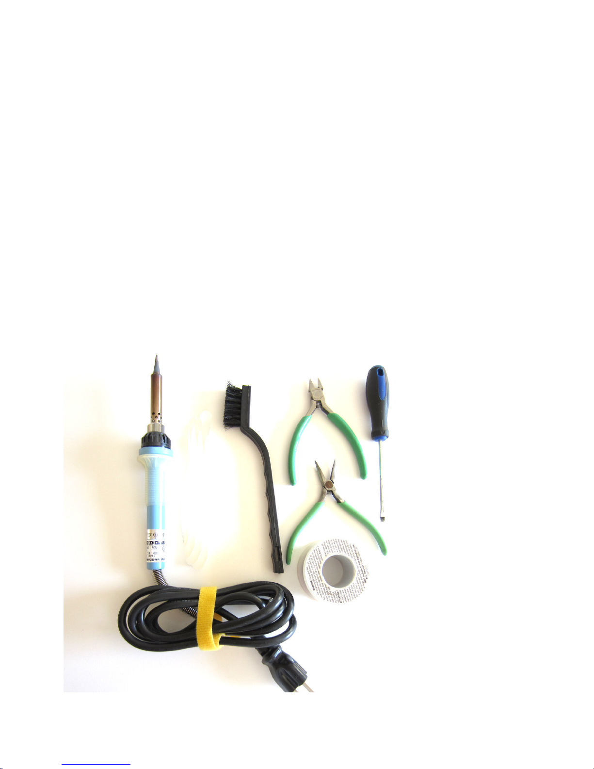
Tools Needed
Soldering Iron
Rosin Core Solder (for electronics)
Small Diagonal Cutters
Small Needle Nose Pliers
Small straight blade screwdriver
Tooth Brush and Rubbing Alcohol (optional)
Multimeter to check voltages (optional and not shown)
22 – Cricket Robot Documentation
Page 23
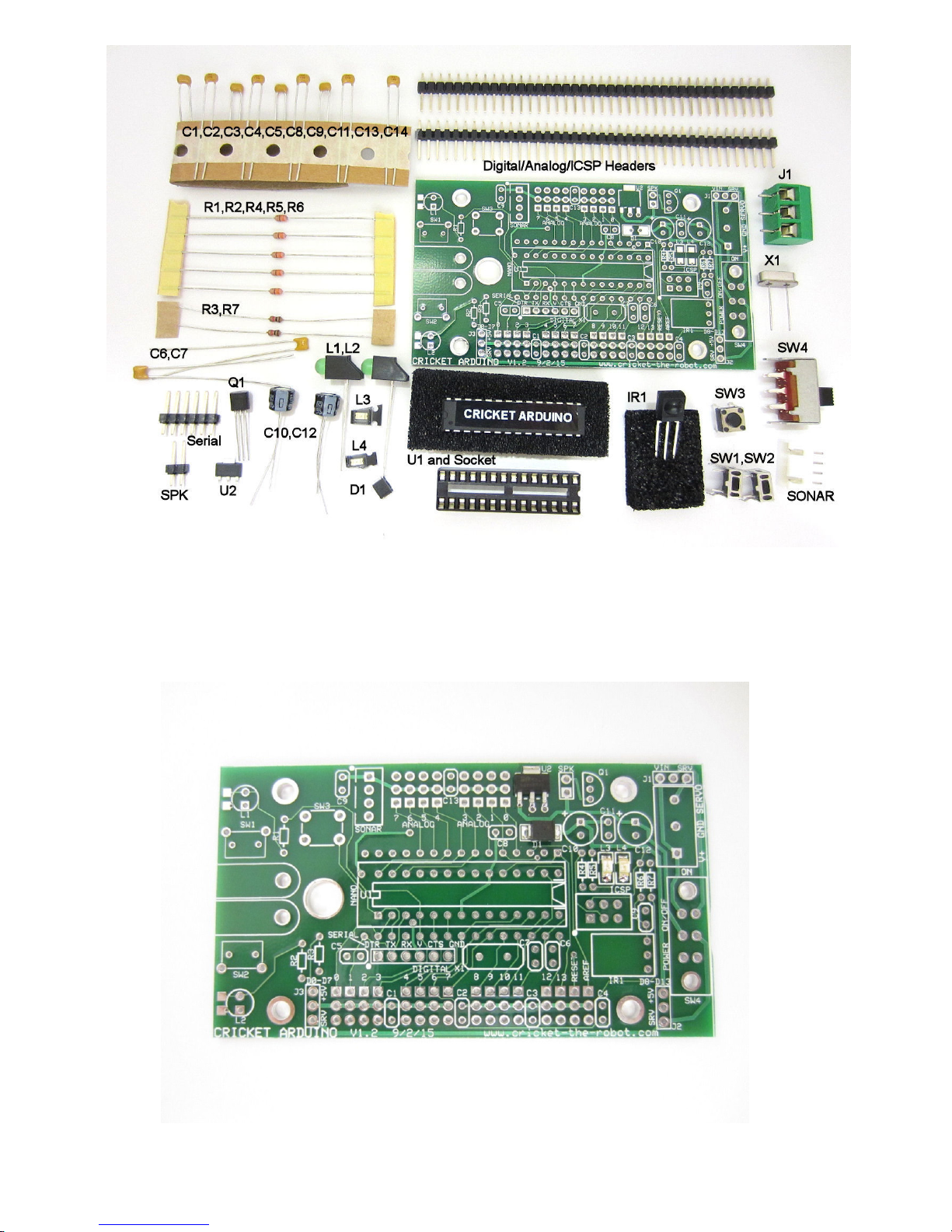
The PC Board and Parts
The PC Board is silkscreened with all of the part designations and outlines of the parts. Be
sure to note any parts that have a polarity or keyed direction before you install them. The
instructions will mention if a part has a polarity or direction. Your kit will have 4 surface
mount parts already installed on the PC board as show in the photo below.
23 – Cricket Robot Documentation
Page 24
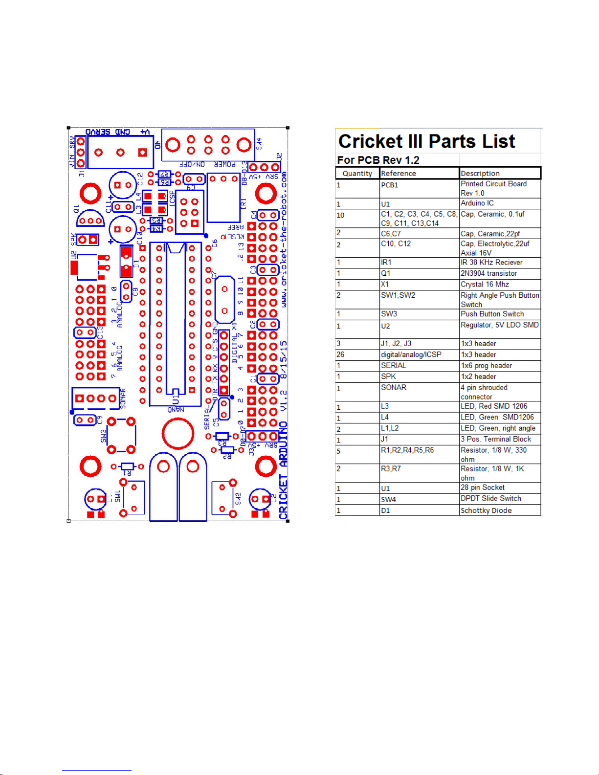
Parts Layout
Use this diagram to help you to locate where the parts are installed. Follow each of the
steps to complete your controller. All controller parts are listed in the parts table.
PC Board Parts Layout Parts List
24 – Cricket Robot Documentation
Page 25
Qty.
Location
Description
Installing the Parts
It’s best to install the low profile parts first. Each of the parts has a picture to help you
identify it. Start with the resistors followed by the capacitors. Resistors are color coded to
indicate their value of resistance. The ceramic capacitor’s value is designated by the
number 104 or 220 printed on the body. Look for the part that matches the picture and be
sure to note any parts that have a polarity which means that they can only be installed in
one direction (small “+” sign).
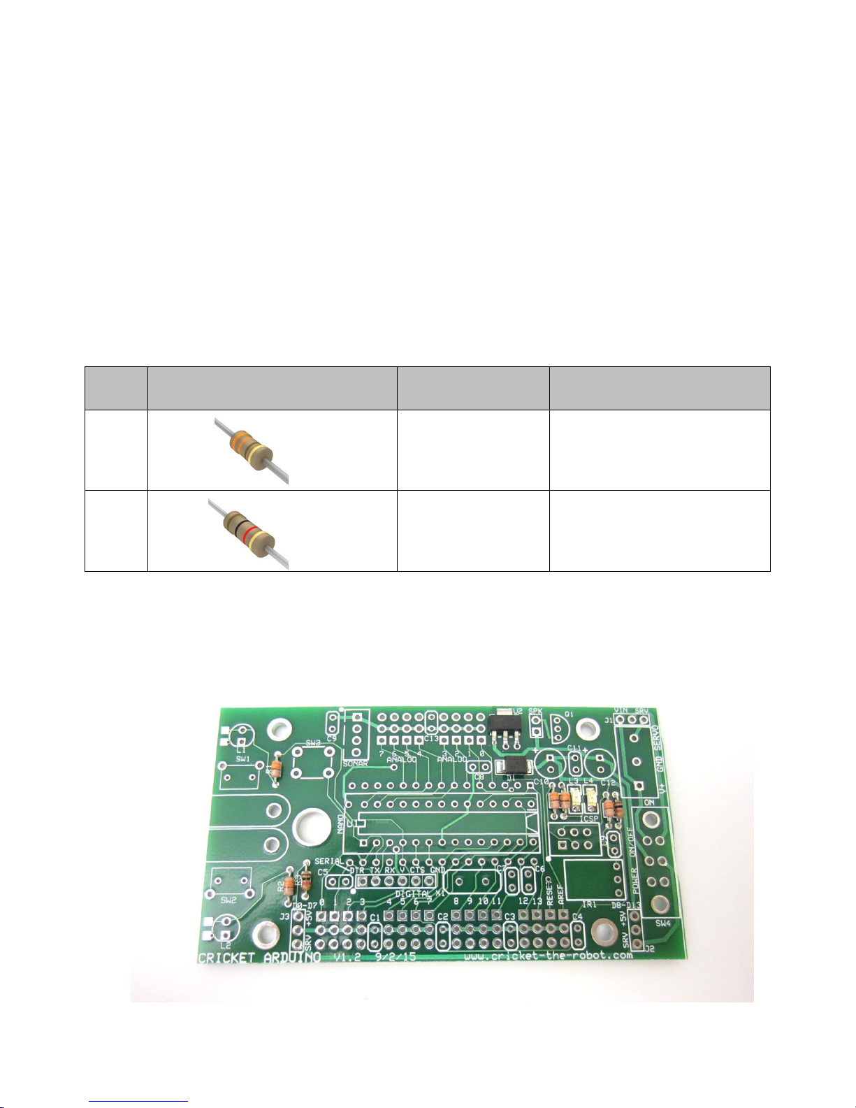
Install the resistors which each have a series of colored bands to indicate their value.
Bend the leads of each resistor so that they form legs which drop into the holes on the
board. You can install all the resistors at once or you can install and solder them one at a
time. Be sure that each resistor is low to the board and not up in the air. Solder each lead
from the back of the board and then clip the lead slightly above the solder joint.
5 R1,R2,R4,R5,R6 330 ohm resistor 1/8W
orange -orange-brown-gold
2 R3,R7 1K ohm resistor 1/8W
brown-black-red-gold
Install R1, R2, R4, R5, &R6. Solder the 2 leads and clip the excess lead.
Install R3 & R7. Solder the 2 leads and clip the excess lead.
25 – Cricket Robot Documentation
Page 26
Qty.
Location
Description
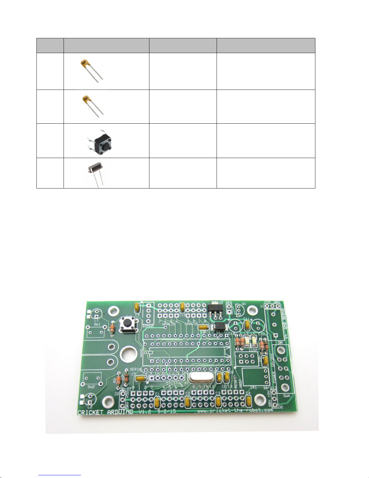
9
C1, C2, C3, C4,
C5, C8, C9,
Ceramic Capacitor
marked 104 0.1uf
C11, C13, C14
2
C6, C7 Ceramic Capacitor 220
0.1uf
1 SW3 Reset Push Button
1 X1 Crystal 16 MHz
Install the ten 0.1uf capacitors which all have the same marking of 104. No lead bending
is needed. They just drop in and there is no polarity. Solder the leads from the back of the
board and clip the excess lead length. Install the two 22 pf capacitors which both have the
same marking of 220. No lead bending is needed. They just drop in. Solder the leads and
clip the excess lead length.
Install the push button switch SW3 and solder the four leads. This part can fit in either of
two directions. Install connector X1 crystal making sure that it is flush to the PC board.
Solder the 2 leads on the back side of the board.
26 – Cricket Robot Documentation
Page 27
Qty.
Location
Description
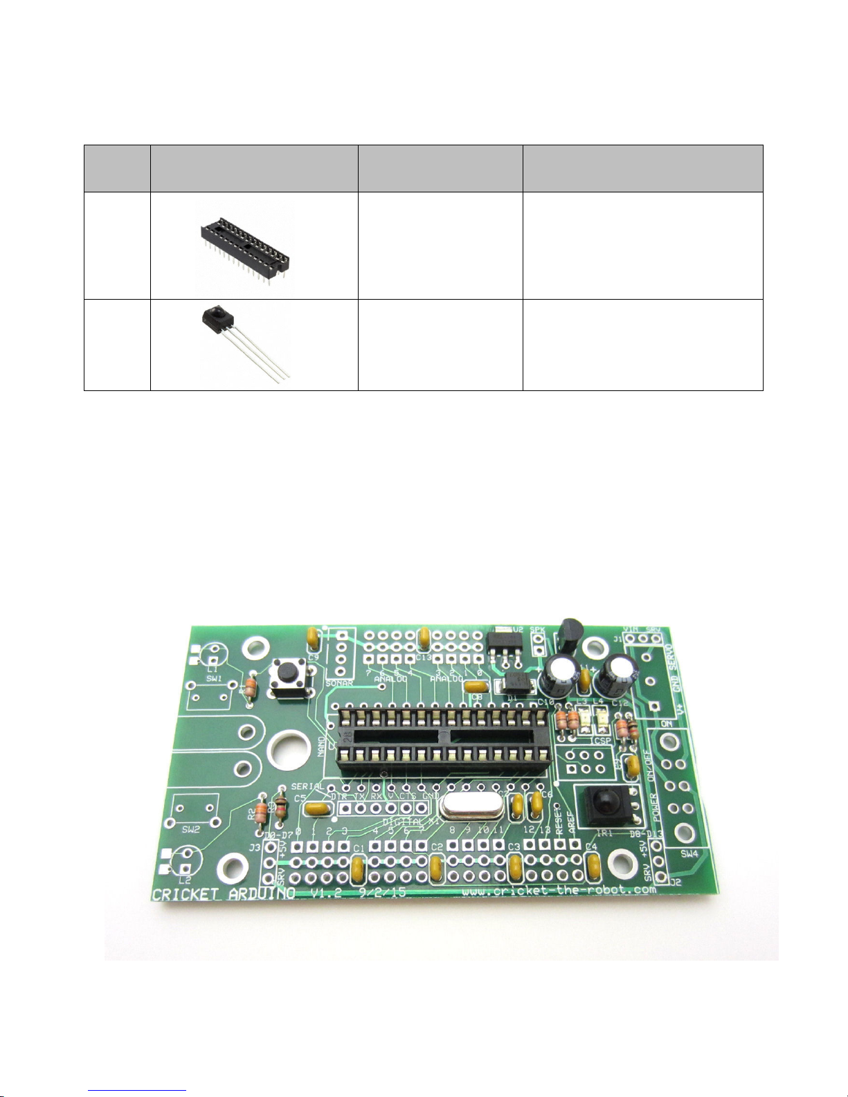
1
Socket Socket for U1 Arduino IC
28 pins
1
Insert the socket for U1 making sure that the notch on one end matches the notch on the
PC Board designation (towards large 0.25” hole). Solder 2 corner pins and then make
sure the socket is flush to the board. Solder the remaining 28 pins.
Install IR1 which is IR Remote Control Sensor by first bending the leads down at 90
degrees at about ¼” from the body so that the part fits in its location on the board. The
bubble on IR1 faces up. Solder the 3 leads and clip the excess lead.
IR1 IR Remote Sensor
27 – Cricket Robot Documentation
Page 28
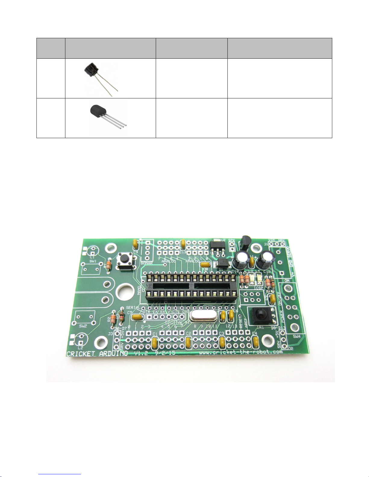
Qty.
Location
Description
2 C10, C12 22uf Electrolytic Capacitor
1 Q1 Transistor
Install C10 and C12 which are 22uf capacitors. Be sure to insert them with the “-” on the
part so that it lines up with the hole labeled with a “-”. There is no “+” marking on this part.
Solder and then clip the excess lead length.
Install transistor Q1 making sure the rounded side matches the silkscreen on the PC
board. You will have to slightly spread the leads and make sure the transistor is close to
the board as shown below. Solder and then clip the excess lead length.
28 – Cricket Robot Documentation
Page 29
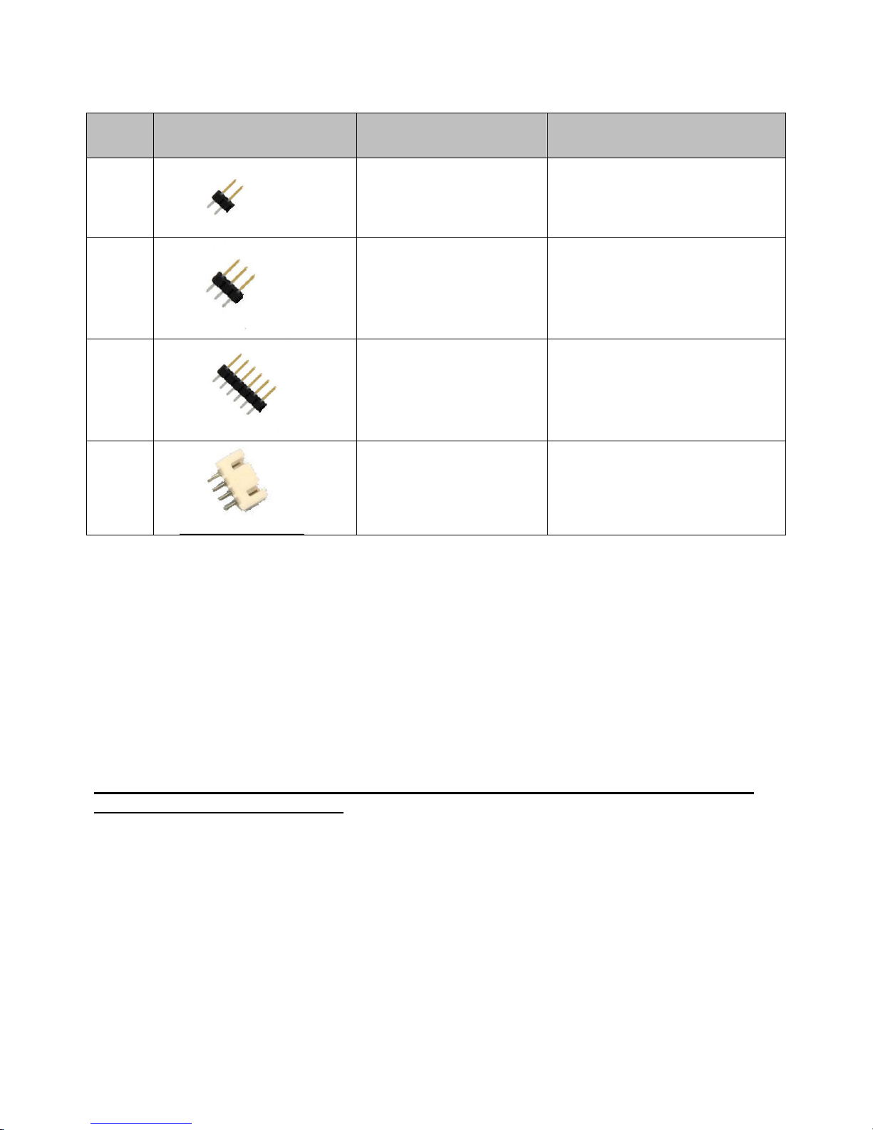
Qty
. Location
Description
1
29
SPK 2 Pin Header
Digital/Analog/ICSP
3 Pin Headers
J1, J2, J3
1 SERIAL 6 Pin Header
1
SONAR 4 Pin Connector
Your kit was supplied with two strips of pin headers. These headers are breakable using
your needle nose pliers. Break the strips into 26 three pin headers and one 2 pin header.
When installing these connectors it is very important that you install them flush and
vertical to the PC Board. They can be held in place with masking tape while you solder
them from the back side. Do not use plastic tape which will melt.
Install SPK which is a 2 pin connector. Solder only one pin, check that the connector is
straight up and down and flush with the board and then solder the other pin.
Connectors for Digital, Analog, and ICSP are three pin headers which were broken from a
long strips found in your kit. Carefully install and solder each connector.
Solder one pin, check that the connector is straight and flush with the board, and
then solder the other two pins. You may install these connectors in groups but be sure
they are straight and flush to the board, solder one pin, check them, and then solder the
remaining pins. You may use masking tape to hold the connector in position while you
solder the first pin.
Install SERIAL 6 pin connector. Solder one pin, make sure the connector is straight and
flush with the board and then solder the other 5 pins.
Install the SONAR connector. Make sure the side with 2 slots matches the silkscreen and
faces SW3 reset switch. Solder one pin, make sure the connector is straight and flush and
then solder the other 3 pins.
29 – Cricket Robot Documentation
Page 30

Qty
.
Location
Description
The above shows 3 pin connectors in the locations pointed to in the arrow. Leave these
connectors off. We will just solder a jumper at those locations rather than using a
connector.
2
2
30 – Cricket Robot Documentation
L1, L2 Right Angle Green LED
SW1, SW2 Feeler Switches
Page 31

Qty
.
Location
Description
Install LEDs L1 and L2 facing out. They are the right angle LEDs which mount on the
edge of the board. Make sure they are straight and flush to the board. Solder one pin,
make sure the LED is straight and flush and then solder the other pin.
Install the switches SW1 and SW2 which snap into place. Solder one lead, make sure the
switches are all the way flush with the board and then solder the remaining 3 leads. The
photo below shows 3 pin connectors in the locations pointed to by the arrows. Leave
these connectors off. We will just solder a jumper at those locations rather than using a
connector.
1 SW1 Slide Switch
1 J1 Terminal Block
1
Install the slide switch. The direction does not matter. The switch will work installed in
either direction. Make sure it is straight by soldering one pin first and the remaining seven
pins after checking it. The two large pins are mechanical mount points which should be
soldered.
U1 ARDUINO IC
31 – Cricket Robot Documentation
Page 32

Install the J1 terminal block by soldering one pin, checking that it is flush and straight and
then soldering the remaining two pins. Add three jumpers as indicated by the arrows.
These jumpers supply power to the Digital Connectors 0-13.
J2 and J3 should be jumpered from the center hole to the lower hole labeled “SRV”. J1
should be jumpered from the middle hole to the left hole labeled “VIN”. Any of the cutoffs
from your resistor installation can be used for these three jumpers.
Straighten the leads of your Arduino IC by bending them against a table top until they are
perpendicular. Do this on both sides. Insert the Arduino IC into the U1 socket noting that
the notch is facing the large 0.25” hole near the reset switch. Press firmly into place
Checkout and Cleanup
The board is now complete and should look like the picture above. If you would like to,
you may test the board by powering it with the battery holder from your kit. Connect the
red lead to V+ and the black lead to GND. When you turn it on, L4 should start blinking.
If you have a multi-meter, check the voltage at any of the center posts of the Analog
connectors.
You may optionally clean the flux residue caused by soldering using a toothbrush and
rubbing alcohol.
32 – Cricket Robot Documentation
Page 33

Assembling Cricket’s Chassis
Cricket’s Chassis is laser cut from ABS plastic. The parts fit together snuggly but still
require gluing to make the chassis strong and stiff. The assembly process is easy and
goes quickly. Just follow the rest of this section to build your Cricket Chassis.
The following diagram shows all of the plastic chassis parts for your Cricket Robot. Each
part is labeled with a letter which will be referred to during the assembly steps.
Tools Needed
ADD COMPLETE TOOLS PHOTO
Xacto Knife
File or Sandpaper (included)
Phillips #3, #2, and #1 screwdrivers
Pliers
Plastic Glue (included)
Spring Clamps or Masking Tape
33 – Cricket Robot Documentation
Page 34

General Assembly Instructions
Cricket’s chassis is made from ABS plastic. You will be gluing it together using plastic glue
which is provided. The supplied glue works well. You can also use Super Glue Gel if you
would like but I’ll warn you that it leaves a white residue which is difficult to clean off.
Otherwise the gluing process is the same. If you do use Super Glue Gel, I suggest that
you use soapy water and a tooth brush to remove any white residue caused by the Super
Glue. Use a minimal amount of glue when assembling the parts. Too much glue makes a
mess. If you do get glue squeezing out, leave it to dry and cut it off later with the Xacto
knife. If you try to wipe it, it will smear.
Cricket’s chassis is laser cut so the corners and notches are sharp. If you would like to
have an extra nice job, a little bit of filing of the corners and edges will make the parts fit
better however filing is optional except for few steps which are noted. On the sections
where filing is directed, you must remove the small ridge to allow the pieces to fit together
smoothly. Some of the part holes and notches may still have plastic slugs in them. You
need to knock these slugs out with a toothpick or other small instrument.
Assemble the Legs
Cricket’s outer four legs are identical
and are made up of 3 parts, the leg
(B) and two pivot pieces (C). These
pieces interlock by sliding C into the
notch on B. The parts must be glued
to assure the legs don’t come apart
with use.
34 – Cricket Robot Documentation
Page 35

Apply the glue sparingly
to the inner notch on
both the leg and the
pivots. Slide the pivots
all the way into the
notch. Slide one 6-32 x
5/8” screws through the
pivot hole to make sure
the holes line up. This is
very important so that
the legs move smoothly.
You may optionally
Clamp or tape each leg
to get a tight joint.
4 outer legs glued and
having a screw to make
sure the pivots are
aligned
35 – Cricket Robot Documentation
Page 36

Attach the rubber feet
part S to each of the 6
legs including the center
legs part D.
36 – Cricket Robot Documentation
Cut the bellow material
(T) into 6 parts with 7
segments each using an
Xacto knife or single
edge razor blade.
Page 37

Glue the bellows to each leg
on the underside near the
leg elbow on all 6 legs.
Note: The bellows are
cosmetic. They give the
legs the appearance of
having hydraulic cylinders. If
you don’t like them, they
may be left off or attached
in a different spot.
All 6 legs complete with
rubber foot pads and
bellows. Note the
location of the bellows.
After the legs are dry,
you may remove the
screws used to align the
pivots.
37 – Cricket Robot Documentation
Page 38

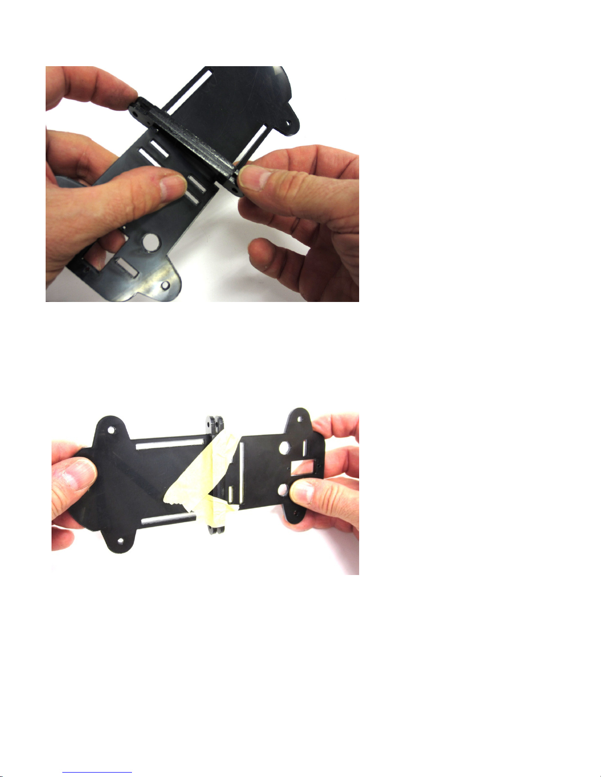
Assemble the Center Leg Beam
Locate two outside center beam plates (F) and one inside center beam plate (G). These
plates are glued together to create a strong center beam to support the center legs. The
laser cutting process leaves a minor ridge that keeps the center beam from being glued
together on flat faces. Use a file or some sandpaper to flatten the inner surfaces. Use 2
nails (provided) to line up the leg beam stack.
File off ridges so that the stack of
3 parts fit together flat. File both
sides of G and one side of each
F part.
Make sure that you apply glue to
both sides of the inside center
beam plate (G) and then add the
outer plates (F). Slide them over
the 16 GA nails supplied using
the small holes which will align
the whole assembly. Clamp or
tape the assembly together.
Allow this assembly to dry for a
while before attaching it to the
chassis body (A). Remove the
alignment nails before the
assembly dries but after you
have clamped/taped it.
38 – Cricket Robot Documentation
Page 39

Use the supplied nails to align
the center beam while clamping
it. The nails are discarded later
after the glue dries.
You may use spring clamps to
clamp the center beam.
OR you may use masking tape
to hold the beam while the glue
dries.
39 – Cricket Robot Documentation
Page 40

Sand the area where the center
beam will rest so that the glue
adheres better.
40 – Cricket Robot Documentation
After the center beam dries,
make sure the inside surface is
smooth using sandpaper, the file,
or the Xacto knife and that the
beam fits snuggly in the notch on
the chassis body. Once you have
checked the dry fit, apply glue to
the inner surface.
Page 41
Push the center beam firmly into
place on the body (A) making
sure that the surfaces mate. The
chassis body is completely
symmetrical so the beam can be
installed on either side.
Whichever side you install it on
becomes the bottom of the
Cricket Robot.
Use masking tape or spring
clamps to hold the beam in place
while the glue dries. This is now
the bottom of the robot.
41 – Cricket Robot Documentation
Page 42

Attaching the Servo Motor Mounts
Find the 3 motor mounts (H). These parts will have a small ridge on the notched end that
slides into slots on the body (A). The motor mounts are symmetrical so they may be
inserted in either direction in the notch on the body (A). File or sand the ridge off and try
dry fitting them into the matching notches on the body (A). IMPORTANT: The motor
mounts (H) must be installed on the same side of the body (A) as the center beam (F & G)
was installed on. When you glue the motor mounts in place, don’t worry about a little glue
squeeze out. Cut it off with a Xacto knife after it dries. I suggest that you don’t try to wipe it
off because it makes a mess of the body.
File or sand off the small ridge
on each tab as shown.
42 – Cricket Robot Documentation
Apply glue sparingly on each
side of the tab.
Page 43

Left Motor Mount
Center Motor Mount
Right Motor Mount
Insert each of the three motor
mounts (H)
Make sure each of the three
mounts (H) are perpendicular to
the chassis body. You may tape
or clamp them if you like but they
should be OK just drying in
place.
43 – Cricket Robot Documentation
Page 44

Install the PC Board Mounts
Find the 4 PC Board mounts (N). The parts are used to mount the Arduino controller. The
mounts have a small ridge on the notched end that slides into 4 slots on the body (A). Be
sure to note the orientation of these mounts as they can be installed backwards. File or
sand the ridge off and dry fit them into the matching notches on the body (A) before gluing
them. IMPORTANT: The motor mounts (N) must be installed on the opposite side of the
body (A) as the center beam (F & G) was installed on.
File or sand the ridge so that the
mount (N) can slide easily into its
matching pocket. Dry test fit the
mounts in the 4 locations noted.
44 – Cricket Robot Documentation
Apply a small amount of glue to
each side of the tab and press
the mount into place. Make sure
it is fully seated and that the
small hooks point inward
Page 45

Installing the PCB mounts (N)
4 PCB mounts (N) installed. Note
that they are on the opposite
side of the body from the motor
mounts.
45 – Cricket Robot Documentation
Page 46

Assemble the Leg Control Arms
Find two leg control strips (J) and two retainers (K). Dry fit the retainer onto the strip. If the
retainer will not fit on the arm, use a file or sandpaper to lightly fit the parts. The two leg
control arms are mirror images for right and left sides. The retainer is attached to one side
with the small round circle pointing up and on the other Control Strip with the small round
circle pointing down. See the assembled photo if this is not clear.
Leg Control Arms (J)
Retainers (K)
Be sure to note the
orientation of the retainers in
following photos.
46 – Cricket Robot Documentation
If the retainers will not slide on,
file or sand the outside of the
notch.
Page 47
Apply a small amount of glue to
the mating surfaces and press
the retainers on each of the
Control Strips. Do not apply glue
to the inner notch which is where
the servo horn will ride.
Left Control Arm
Right Control Arm
Key holes facing outward
This shows the Left Control Arm
with keyhole facing down.
Hole
This shows both the Right Control
Arm and the Left Control Arm. The
holes at the end of the slot face
outward.
Left Control Arm
47 – Cricket Robot Documentation
Page 48

Assemble the Sonar Bracket
The Sonar mount bracket is made up of parts (L) and (M). The upright (L) has a tab that
must fit into a slot on the base (M). Check the fit and if it is tight, remove the ridge using a
file or sandpaper.
Check the fit and if it is tight,
remove the ridge using a file or
sandpaper.
Apply a small amount of glue to
each side of the tab.
Press the upright tab into the
base slot. Make sure it is fully
seated.
48 – Cricket Robot Documentation
Page 49

The Completed Sonar Bracket
Assemble the Sonar Servo Linkage with the servo horn adapter (R) the 4-40 round ¾”
standoff, 4-40 internal star washer, and a 4-40 x 3/8” flathead screw. These parts are
shown in the photo below.
4-40 flathead Adapter (R) star washer ¾” spacer
Push the flat head screw through the countersunk side of adapter (R). Place the star washer on the
screw. Add a small amount of glue to the screw and then tighten the spacer onto the screw using a
#1 Phillips screw driver.
49 – Cricket Robot Documentation
Page 50

Completed Sonar Servo Linkage
Attach the post to the Sonar Servo
horn using two #0 x 3/16" flathead
sheet metal screws
Tighten the screws with a #1 Phillips
screw driver.
50 – Cricket Robot Documentation
Page 51

Completed Sonar Servo with linkage
ABS Parts of Chassis are Now Complete
You have completed all of the ABS assembly. You should have the completed body, legs,
control arms and Sonar Bracket. The photo also shows a center control arm (right side)
which did not require any gluing. Let everything dry before assembling the legs and other
parts to the chassis body.
51 – Cricket Robot Documentation
Page 52

Installing the Servos into the Chassis
Remove your 3 Hitec servos from their boxes
and remove the standard control horn from
each servo by removing the center screw.
Label the servos “R”, “L”, and “C” on both the
body of the servo and its connector. A black
indelible ink pen works well. These labels
stand for right, left, and center and are
important because we will setup the servos
based on their position on the robot.
There are 12 #4 x 3/8” screws for mounting
the servos.
Install the left servo with the shaft
closer to the front of the robot and the
center beam
Attach the servo with four #4 x 3/8”
self-tapping screws using a #2
Phillips screw driver.
52 – Cricket Robot Documentation
Page 53

Left servo shown installed
Install the right servo the same way
with the shaft and wire towards the
front of the robot
Insert the center servo with the shaft
to the left side of the robot as shown.
Use only 2 screws because this servo
will be removed later.
Install with only 2 screws because
this servo will be removed later.
53 – Cricket Robot Documentation
Page 54

Install the sonar servo with the
linkage in the opening at the front of
the robot. The shaft should face the
center of the robot as shown.
Mount the sonar servo with the 2
screws from the supplied HS-55
accessories inside the box using a #1
Phillips screw driver.
The completed sonar servo
installation should look like this.
54 – Cricket Robot Documentation
Page 55

Verify your servo installation against
these photos. Route all servo wires
through the left access hole in the
body as shown
Your servo wires should be loosely
routed as shown. Later we will neaten
the wires up with wire ties
55 – Cricket Robot Documentation
Page 56

Installing Cricket’s Legs
We will now install the legs using six 6-32 x 5/8”
machine screws and six self-locking nuts.
Attach the 4 outer legs (B) by pushing
a 6-32 x 5/8” screw through the top of
the leg through the body. Do the
same on all four corners of the robot
6-32 x 5/8” Screw and
6-32 Self Locking Nut
Using a pliers and a #3 Phillips
screwdriver, tighten the 6-32 selflocking nut onto the screw from the
bottom of the robot. Tighten all the
way until the screw will not turn
anymore and then loosen one half
turn. Make sure the legs move freely.
If they do not, loosen the screws a
little more until they move freely.
56 – Cricket Robot Documentation
Page 57

Attach the 2 center legs (D) by
pushing a 6-32 x 5/8” screw through
the center beam and the leg. The
screw head should be closest to the
right and left servos.
6-32 x 5/8” Screw and
6-32 Self Locking Nut
Tighten all the way until the screw will
not turn anymore and then loosen
one half turn. Make sure the legs
move freely. If they do not, loosen the
screws a little more until they move
freely
57 – Cricket Robot Documentation
Page 58

Installing the Leg Control Arms
Locate the Leg Control Arms you
assembled earlier and four 2-56 x ½”
machine screws
Select the control arm for the right
side of the robot noting the round
keyhole pointing down as shown.
Insert the machine screw through the
arm and into the hole in the leg. The
screw will self-tap itself into the
plastic. Tighten the screw all the way
and then pack it off about one full
turn. Repeat on the front leg and then
make sure the legs on the right side
move freely. Repeat these steps on
the left side.
58 – Cricket Robot Documentation
Page 59

Your leg control arm on the left side
should look like this. Note the round
keyhole pointing down.
Your leg control arm on the right side
should look like this. Note the round
keyhole pointing down.
59 – Cricket Robot Documentation
Page 60

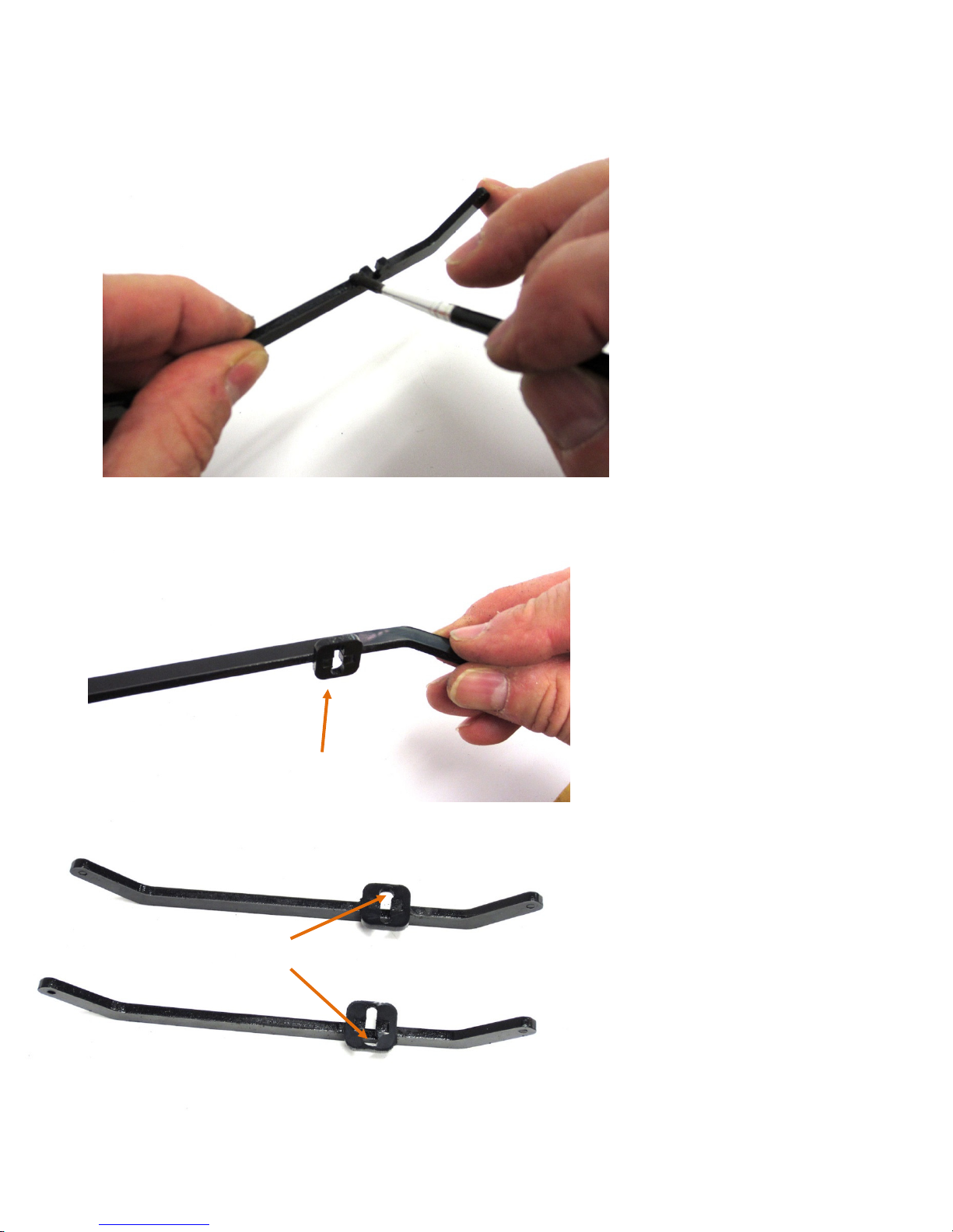
The center leg control arm (E) is
installed on the front of two posts
coming up from the center legs (D)
with the round Keyhole facing down
as shown.
60 – Cricket Robot Documentation
Add two 4-40 x ½” screws through the
center leg control arm as shown, Be
sure the arm is in front of the posts.
Page 61

Secure the center control arm
(E) to the center legs as
shown using two 4-40 x ½”
Screws and 4-40 Self
Locking Nuts. The keyhole in
the center control strip should
face with the round part of
the hole down.
Your robot should look like this photo
with all six legs installed. Make sure
all the legs move freely and loosen or
tighten the leg screws as needed.
61 – Cricket Robot Documentation
Page 62

Installing the Battery Holder
Clean the area on top of the robot
towards the back with rubbing alcohol
or water. Let it dry.
62 – Cricket Robot Documentation
Attach two strips of double sided tape to
the back of the battery holder by removing
one side of the protective paper.
(Only one tape is shown. There are two)
Page 63

Remove the protective paper on the
other side of the double sided tape
and press the battery holder into
place. The battery holder should be
placed all the way up to the center
brace and centered between the
servo control arms.
There should be a small amount of
space between the battery holder and
the rear leg pivots.
63 – Cricket Robot Documentation
Page 64

Installing the Speaker
The speaker is installed by gluing it
face down to the chassis body in
front of the center servo mount as
shown. Installing it face down may
seem wrong but the chassis acts
as a sound board with the sound
exiting the rear of the speaker.
64 – Cricket Robot Documentation
Glue the speaker by holding it
firmly in place and putting three
drops of glue evenly spaced
around the perimeter. Use a
spring clamp or tape to hold the
speaker in place while the glue
dries.
Page 65

Completing the Feelers
The feelers with feeler switch actuators have
been assembled for you. You must only add the
small glass bead and bend the feeler to shape.
The bead protects people and animals from
being poked by the sharp end of the feeler. You
may also bend the end of the feeler into a tiny
loop if you don’t want to use the bead.
Slide a supplied glass bead onto the feeler. Add a small drop of the supplied glue (or Crazy Glue) to
the end of the wire and then carefully slide the bead into the glue. Let this dry before handling further.
Note: The bead protects people and animals from getting poked by the sharp wire. As an
alternative you may simply bend a small loop into the end of the feeler wire.
65 – Cricket Robot Documentation
Page 66

Installing the Feelers
Using two 2-56 x ¼” machine screws and 2-56
self-locking nuts, attach the feelers to the control
board. The little nubs on the feeler switch
actuators (P) must face the switch button.
Tighten the screw with a #1 Phillips screw driver
and pliers until tight and then back off about a
half turn. Make sure the feelers operate the
switches smoothly
66 – Cricket Robot Documentation
Page 67

The feelers need to have a couple of
bends in them so that they point
outwards from Cricket’s body.
The first bend can be done with your
hands. Gently bend the two feelers
away from each other so there is about
½” to ¾” between them.
Next take a pair of pliers with the
Cricket controller lying on a table and
bend the feelers about 1” from the
switch actuators so they point outward
as shown. The bend angle is not
critical. The idea is for the feelers to
reach out past to body and touch
something before the robot crashes
into the object.
67 – Cricket Robot Documentation
Page 68

You may now install the controller on
your Cricket chassis. Make sure all of
your wires are exiting outward from the
chassis as shown. Carefully slide the
controller over the sonar post. When it
is resting on the four PCB mounts
carefully push down on it until it snaps
into place.
Connect the speaker to the
connector labeled “SPK: on
the PC board. The
connector is next to the
terminal block. The yellow or
red wire faces in towards the
center of the robot. The
black wire is near the edge.
68 – Cricket Robot Documentation
Page 69

Connect each of the service
noting the labels you added to
each connector. The connections
are show in the table below and
correspond to the numbers on
the connectors along the left side
of the robot. The yellow wire
faces in towards the center of the
robot. THIS IS IMPORTANT.
The photo at the left shows the
correct orientation for each servo
connector as you plug them in.
Plug the servos into your
controller using the following
connections:
Right Servo 9
Left Servo 10
Center Servo 11
Sonar Servo 12
69 – Cricket Robot Documentation
Page 70

Connect the battery holder to the
controller by connecting the red
and black wires. The photo
shows long wires but your wires
will already be cut to the correct
length.
The red wire goes to the terminal
labeled V+ which is the terminal
closest to the center of the
board.
The Black wire goes to the
terminal labeled GND which is
the center terminal.
Be sure you have these
connections correct so that you
don’t damage your controller.
You may have to loosen the
terminal with a straight blade
screw driver. Insert the wire and
then tighten the screw.
70 – Cricket Robot Documentation
Insert the AA batteries into the
holder noting the correct
polarities print on the bottom of
the holder. Be careful not to
pinch the battery leads.
Page 71

NOTE:
The Servo
yellow wire faces toward middle of the PC board.
Before you power your Cricket up for the first
time, verify that you have connected the motors
and battery as shown below.
SPK-speaker wire
No Connect
Black Battery
Red Battery
9-Right Servo
10-Left Servo 11-Center Servo
12-Sonar Servo
71 – Cricket Robot Documentation
Page 72

Centering the Servos
Your servos are now electrically connected and you have a battery connection. When the
controller is turned on, it will center each servo to its middle position. You have no
mechanical connection between the motors and the legs so the motors will turn without
moving anything. This allows the motors to be centered in the correct position before we
install the control arms that will move the legs. If the motors are not centered before the
mechanical connection is made, the legs might be forced into a bad position possibly
damaging the robot.
Turn on your controller using the switch next to the batteries and the controller will center
the servos, make a beep, and then pause for a couple of seconds. During that pause, turn
off the robot. If you miss the pause; just turn the controller off and then on again. When
you hear the first sound, turn the switch off. This procedure allows us to center the servo
shafts to the correct position before attaching the servo horns which will be used to move
the control arms.
Installing the Servo Horns
Inside the accessories package for the Hitec 311 servos are extra horns. Horns are the
plastic pieces that screw onto the servo shaft. We will not be using the default horn which
comes attached to the servo. Locate the horn and pieces shown in the photo below. Two
of the horns have an extra-large hole drilled in the end spot and the third horn has an
extra-large hole in the third spot. The ones with the hole in the end are the right and left
horns and the other is the center horn. Each horn has a serrated and a smooth side.
The accessories package also has four rivets which are normally used for mounting the
servo. We will be using one rivet as a bearing point for each horn. On the right and left
horns, place a rivet through the 2-56 x 3/8” machine screw and screw it into the first hole
on the serrated side of the horn. On the center horn, place a rivet through the 2-56 x 3/8”
machine screw and screw it into the third hole on the non-serrated side of the horn.
Horn Assembly Parts:
Horn, Rivet from
Servo kit, 2-56 x 3/8”
screw, and original
horn screw.
72 – Cricket Robot Documentation
Page 73

Right and left horns
Serrated side up
.
Center horn
Serrated side down
Here’s a photo showing the
completed servo horns
Horn adapter fits on
servo shaft.
Screw retains both
horn and horn adapter
to servo shaft.
Before you install the horns on
the right and left sides, make
sure the slot they ride in is free of
glue or plastic flash. Check that
the screw and rivet ride smoothly
in the slot.
73 – Cricket Robot Documentation
Page 74

Install the horn adapter in it most vertical
position. If you can’t find a shaft position
that is perfectly up and down, pick the
closest position to vertical. Be very careful
to not move the servo shafts as you install
each of the adapters. If you think you may
have moved the shaft, turn on the
controller to center the shaft and turn it off.
Once the adapter is in position, add the
horn. The serrations should be facing in
and mesh with serrations on the
adapter which keep it from sliding
around. Line up the bottom edge of the
horn with the adapter and screw the
assembly in place with a #1 Phillips
screwdriver.
74 – Cricket Robot Documentation
This photo shows the left side
horn in place. Repeat the
process on the right side
again making sure the adapter
is as vertical as possible.
Page 75

Remove the center servo
which was installed with just
two screws. Add the horn
adapter installing it in the most
vertical position you can find.
Once the adapter is in
position, add the horn. The
serrations should be facing in
and mesh with serrations on
the adapter which keep it from
sliding around. Line up the
bottom edge of the horn with
the adapter and screw the
assembly in place with a #1
Phillips screwdriver.
Reinstall the center motor
by tipping it through the
motor mount and inserting
the rivet and screw bearing
point through the center
keyhole.
75 – Cricket Robot Documentation
Page 76

Install all four screws
to retain the center
servo motor
76 – Cricket Robot Documentation
Check that your robot
center motor installation
looks like the photo at the
left. The rivet bearing point
should be poking through
the center control arm as
shown.
Page 77

Turn your robot over and he should look like the above photos. The wires are just
hanging at this point but we will neaten them up and use wire ties to hold them in place.
If you would like, you can turn your robot on and let him walk a bit. If you hear any
binding in the motors, you can remove the horns and repeat the centering procedure.
If the robot fails to walk correctly, recheck the motor connections. If the right, left, or
center motor connections are swapped, the robot will act very strange.
77 – Cricket Robot Documentation
Page 78

Installing the Sonar Module
Attach the sonar (ultrasonic module) to
your bracket with two #1 panhead
screws. You will need to slightly tip the
module to install it in the bracket. The
screws are at diagonal positions.
Note: The photo shows the sonar post
and screws which we already installed
on the servo. Please ignore
Sonar module and bracket with
screws installed
78 – Cricket Robot Documentation
Page 79

Locate your sonar cable, a 4-40 x 3/8”
panhead screw, a flat washer, an
external star washer, and an internal
star washer.
Internal
Washer
Screw
External
star
star
Connect the cable to your sonar
module with the ribbed side facing
as shown.
Place the flat washer on the screw and
push it through the hole in the sonar
bracket. Add the external star washer
and then the internal star washer.
Note: The external star grabs the
plastic of the bracket and the internal
star grabs the top of the post. This
keeps the sonar module from slipping.
Ribbed side
79 – Cricket Robot Documentation
Page 80

Without dropping the star
washers insert the screw and
bracket assembly onto the sonar
servo post and tighten it with a
#1 Phillips screwdriver. Try to
hold the post from turning so that
the servo maintains it center
position.
Note: Later if you find that the
sonar module does not face
straight forward you can loosen
the bracket, move it, and
retighten the screw.
80 – Cricket Robot Documentation
Plug the sonar module into
the controller board
Page 81

Cleaning Up the Wiring
Your robot will look nicer if
the wires are not hanging all
over the place.
Neaten up the four servo
wires by removing the slack
by pushing them through the
hole in the chassis.
Wire Tie
Use one of the supplied wire
ties to retain the four servo
wires from moving around.
Allow a little bit of slack in
case you need to disconnect
any of the servos
81 – Cricket Robot Documentation
Page 82

Wire Retainer
Attach the nylon wire retainer
on the side of the center servo
by peeling the backing off and
pressing it into place.
Route the right and left
servo wires through the
wire retainer. Make sure
there is some slack so
that the wires are not in
the way of the center
servo horn.
82 – Cricket Robot Documentation
Page 83

Fold the dangling wires
into a neat bundle and
tuck it between the sonar
and center servos.
Use two more wire ties to
retain the wire bundle in
place.
Note: There is a small
amount of slack one the
right and left servo wires
to clear the motion of the
center servo horn’s
movement.
83 – Cricket Robot Documentation
Page 84

Final Checkout
Your Cricket Robot should look like this photo from the top. Make sure your wires are not
hanging out. The legs should center as shown when turned on and the sonar should be
facing forward.
From the side, the right and left
motor horns should be vertical
and the horn should be flush
with the bottom of the horn
adapter.
84 – Cricket Robot Documentation
Page 85

Your sonar module
should face straight
forward and the
feelers should look
like the photo.
From the bottom, the
center servo horn should
be vertical and the wires
should be out of the way of
moving servo horns. Your
feelers should extend in
front of the robot so they
detect objects before the
leg runs into it.
85 – Cricket Robot Documentation
Page 86

Your sonar cable should exit
from the bottom of the sonar
module and bend through a
graceful loop into its
connector on the controller.
This bend allows for
movement of the wire as the
sonar module turns right and
left.
Recheck that your feeler
switches both click when
the feelers are pushed.
86 – Cricket Robot Documentation
Page 87

Beep Beep!!
Your Cricket Robot is complete. Place him in an open area and turn him on. He should start
walking around and avoiding obstacles. In most cases the sonar should detect an obstacle but
if it misses, the feelers will detect the obstacle. When Cricket detects something in the way, he
should back up, scan with the sonar and pick a way around the object. Cricket will make
random sounds while walking around. If you have problems with your Cricket, refer to the
troubleshooting section of this manual.
If you find that your Cricket does not walk in a straight line, try adjusting the horn alignment with
the horn adapter on the right and left servos. Moving the horn down on the serrated teeth
against the adapter will slow that side down.
87 – Cricket Robot Documentation
Page 88

You may override Cricket’s autonomous movement using the remote control. Try pushing
the right, left, up and down buttons to see how it affects Cricket’s motion. Pushing the up
button will make him walk forward faster. Right and left will make him turn that direction
and down will make him backup. Pushing the number 0-9 buttons will cause Cricket o
make various sounds. Try them out. The Prev. Chan/Record/Enter button makes Cricket
dance the Cha-Cha.
If you find anything is not as it should be, refer to the troubleshooting section of this
manual for tips on how to fix your Cricket.
Enjoy your Cricket Robot!!!
Troubleshooting
If you find that your Cricket isn’t acting like he should, here are some things to check:
Low Battery – A low or dead battery can exhibit all kinds of funny behavior. Cricket
could start chirping constantly, resetting repeatedly, or just stop walking. This
occurs because the Arduino controller can detect a brownout situation and will
keep trying to reset to recover. This causes the initial turn on chirping to keep
happening with no movement of the legs.
Remote Doesn’t Work - If the remote fails to work, it may need to be reset.
Press and release the TV button. See the section on reprogramming your remote
Legs Not Working – If any of Crickets legs appear to not be moving correctly, try
looking at the linkages. Something may have loosened. If a motor is not working at
all, check the wiring and make sure the motor connectors are seated. Check that
the joints on each leg are tight but not so tight that the leg can’t move freely. Make
sure if this is a newly built robot, that his motors are plugged into the correct
connector
Cricket pulls to one side or the other when walking straight – Adjust the alignment
of the right or left horn adapter to horn. Moving the horn down in the adapter slows
that side down.
Unexplained Erratic Operation – Sometimes fluorescent lights or camera flashes
can falsely trigger the remote control sensor. This should be very rare. Try running
Cricket in another location to test for this problem
Nothing happens at all – If Cricket completely stops working, the battery may have
gone dead or the Arduino controller may have a problem. If a multimeter is
available, check the power at the connector on the controller board. Also try
reloading the control program. If the Arduino software can’t recognize the hardware
there is a more serious problem.
88 – Cricket Robot Documentation
Page 89

If the Arduino Programming doesn’t recognize the Cricket Arduino, you've either
forgot to attach the cable, the battery is low or turned off, or a more serious
problem has occurred.
Sound is not very loud or non-existent. Check the speaker wiring and that the
speaker is tightly glued to the chassis
If you can’t figure the problem out, contact us. Replacement parts can also be purchased
from us. Documentation and program updates are available at:
http://www.cricket-the-robot.com
You can reach me through email at:
henryarnold@earthlink.net
89 – Cricket Robot Documentation
Page 90

Appendix A – Schematics
90 – Cricket Robot Documentation
Page 91

91 – Cricket Robot Documentation
Page 92
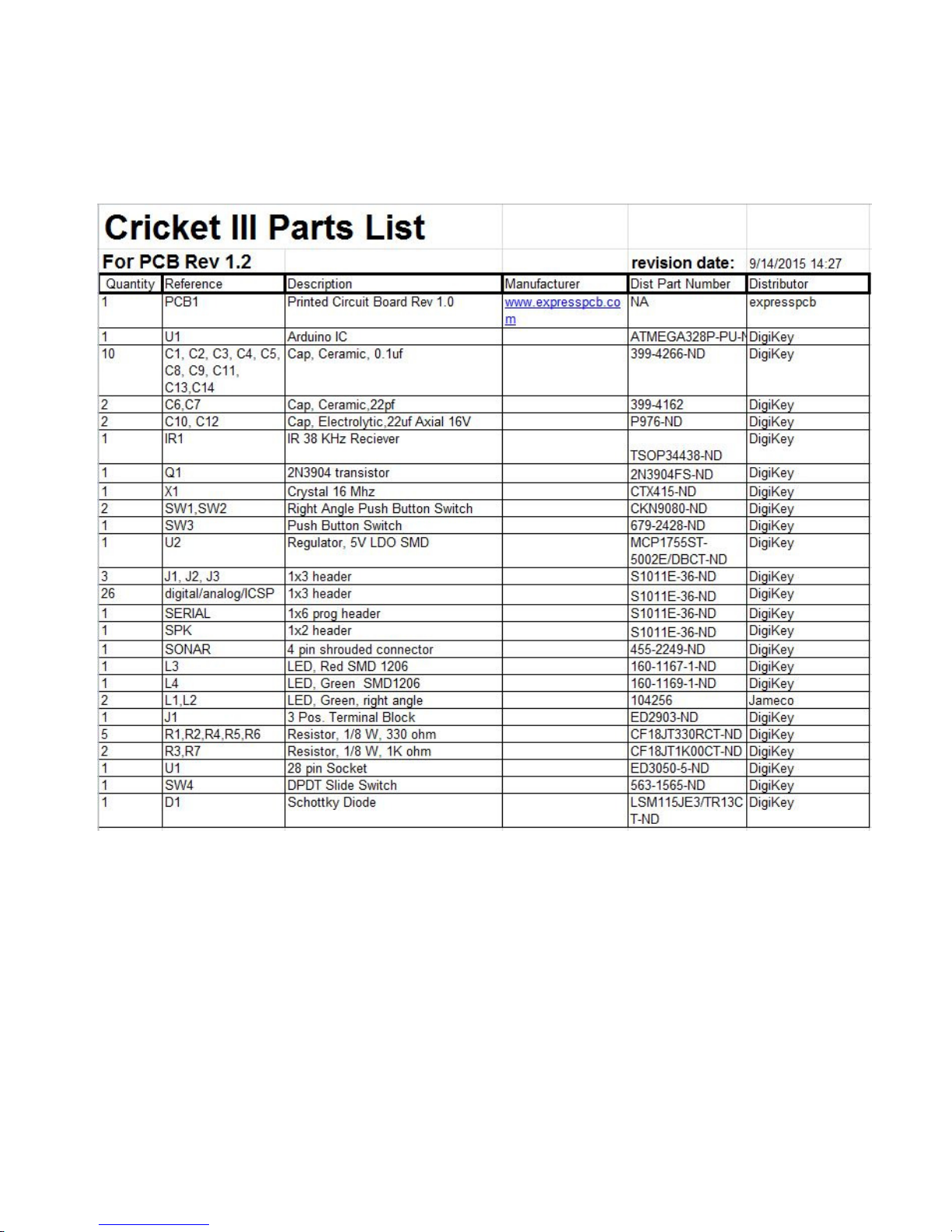
Appendix B - Parts List
92 – Cricket Robot Documentation
Page 93

93 – Cricket Robot Documentation
Page 94

Appendix C - PC Board Layout
All Layers
Parts Layout
94 – Cricket Robot Documentation
 Loading...