

Page 1

EVDO USB Modem
A600
Page 2

2
1. BEFORE USING A600 ...............................3
About this User’s Manual ..........................3
Product Overview ......................................3
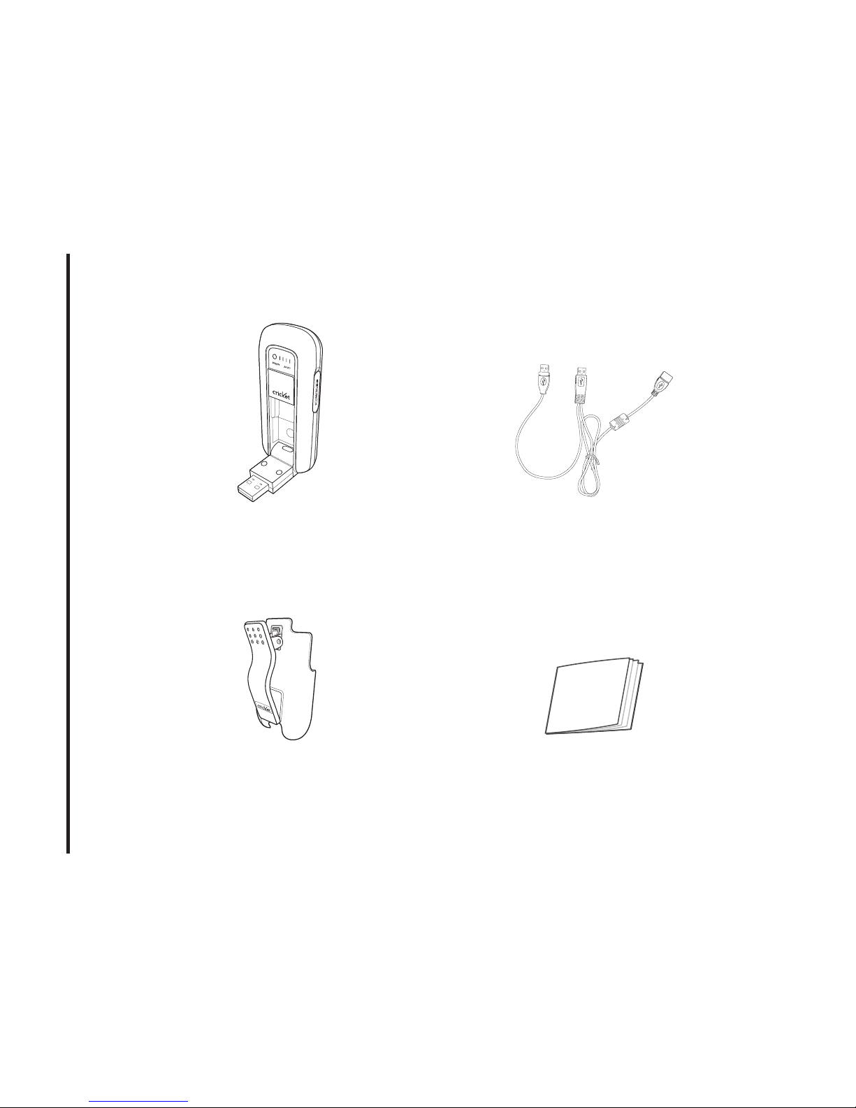
Product Package Contents .......................3
Introduction to A600 USB Modem ...........5
Product Features .......................................5
Product Handling .......................................6
Configuration .............................................6
2. INSTALLATION AND SETUP FOR
CRICKETLINK ...........................................7
Setup Program - Windows ........................7
Setup Program - Mac OS X ................... 12
3. USING CRICKETLINK ............................ 15
Features .................................................. 15
Getting Started ....................................... 15
Connecting ............................................. 16
SMS Messaging ..................................... 18
4. CRICKETLINK PREFERENCES ........... 21
General Preferences .............................. 21
WWAN Specific Settings ....................... 21
VPN Settings .......................................... 22
SMS Settings .......................................... 23
Additional Features ................................ 24
5. INSTALLING A600 .................................. 28
Recommended System Requirements . 28
Installing Software ..................................28
Using the Device ....................................30
Unplugging or Ejecting the modem .......30
Remove the A600 from your laptop ......36
Using the USB Modem Extension
Y Cable ...................................................36
CARE AND MAINTENANCE .....................38
SAR INFORMATION ...................................39
SAFETY INFORMATION ............................40
FCC COMPLIANCE INFORMATION .........41
U.S.A. U.S.FEDERAL COMMUNICATIONS
COMMISSION RADIO FREQUENCY
INTERFERENCE STATEMENT .................42
CONTENTS
Page 3

3
1. BEFORE USING A600
About this User’s Manual
You will find all the information you need
to install and use the A600 in this user’s
manual. Before using the A600, you must
properly install the A600 by closely following
the installation instructions.
Instructions
• Install the A600 software by inserting
the A600 USB Device into your PC. The
installation software is included in the
A600 modem memory. When you insert
the A600 into your computer, USB driver
will be installation automatically.
• It is highly recommended that you read
the safety precautions described in this
manual before using the A600.
Product Overview
Thank you for purchasing A600 USB
Modem.
The A600 is a 3G wireless device that
enables high-speed wireless
communication from your PC. The A600 is
simple to install and use.
Product Package Contents
The following items are included in the
product package. If any of the items listed
below are missing, please contact the retail
location where you purchased the product.
Page 4
4
1. BEFORE USING A600
A600 Wireless USB
Modem
A600 Screen Clip
USB Modem
Extension Y Cable
Quick Start Guide
Page 5

5
1. BEFORE USING A600
Introduction to A600 USB
Modem
The A600 is designed for your PC’s USB
port, which is available in most PC models.
The A600 can be used to access the Internet, your company’s intranet, or you can use
it to send and receive email. It is extremely
useful when you are away from the office,
on the road, or wherever wireline Internet
access is not readily available.
Product Features
- Power management: The A600 utilizes
power management and system overhead
reduction functions provided by the USB
interface for maximum power savings.
- Antenna design: Efficient, innovative
design optimizes data transfer rate and
sensitivity to network signals.
- Extension Y Cable connector: Connect the
Y cable to two separate USB ports of your
computer to deliver sufficient power when
needed to increase RF performance, and
to solve clearance issues.
- USB Modem that supports Type A USB
Port interface.
- Supports North American PCS (1900
MHz), Cellular (800 MHz) and Aws (Tx
1700MHZ, Rx 2100MHZ) bands.
- Utilizes Qualcomm QSC6085 chipset.
- Supports 3G network technologies.
- Supports Windows 2000, XP, Vista and
Apple Macintosh systems with installed
host software and driver.
Page 6

6
1. BEFORE USING A600
Product Handling
- Do not put any adhesive label on the USB
connector. It may leave a sticky residue
that can cause problems inside the PC
USB port.
- The A600 USB device should easily slide
into the USB port. Do not force the A600
into the USB port as it may cause damage
to the modem and/or the port.
- Keep the A600 in a dry and clean place.
(Storage temperature: -22°F to 149°F
[- 30°C to 65°C]). Keep your device away
from liquids, dust and excessive heat.
Configuration
To use the A600, you should install the
connection manager software included in
the A600 modem memory and configure
the A600 USB device. See the next section
for more information on software installation
and USB device configuration.
Page 7
7
2. INSTALLATION AND SETUP FOR CRICkETLINk
This section will guide you through the installation and setup process for CricketLink.
Before getting started, you should become
familiar with the documentation that came
with your USB Modem.
Getting Started
To install CricketLink:
1. Turn on your computer then close all
applications.
2. Insert the A600 modem into your USB
port.
3. Your computer recognizes A600 modem
and starts installation sequence automatically. If set up does not automatically
start, click the Start button on the taskbar
then choose Run. Type D:\Start (where D
is the letter of your CD-ROM drive) then
click OK.
4. Follow the steps in the next section.
Setup Program - Windows
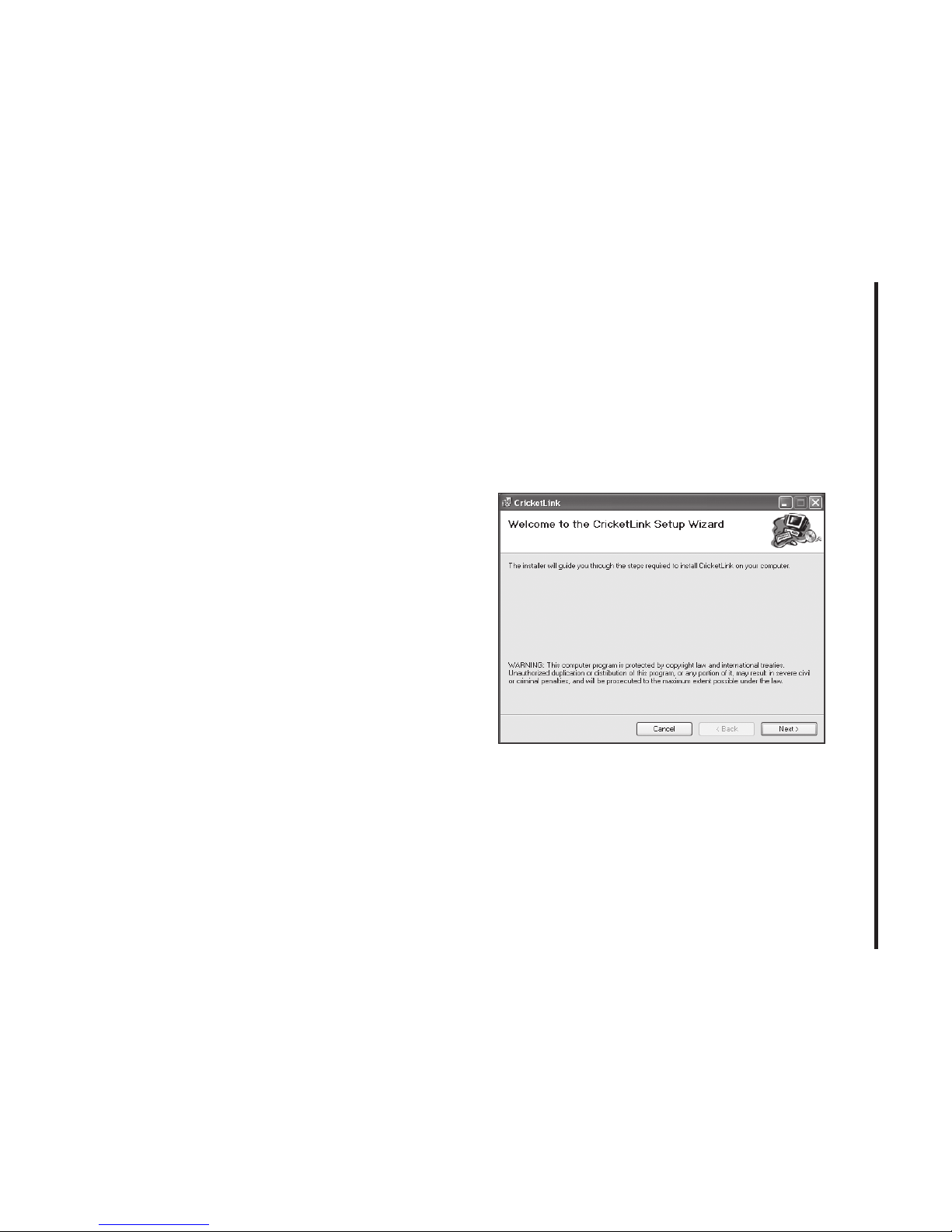
S TEP 1: The “Welcome to the CricketLink
Setup Wizard” screen appears. Click the
“Next” button to continue with the installation process.
Page 8
8
2. INSTALLATION AND SETUP FOR CRICkETLINk
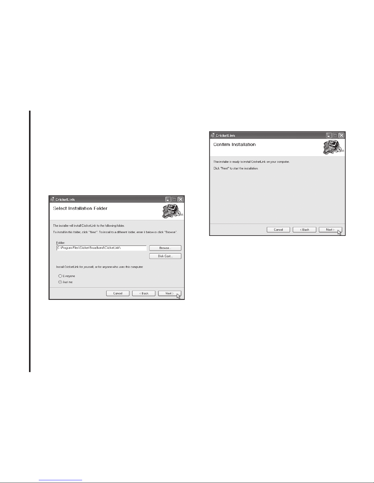
S TEP 2: You are now ready to select
the location on your computer where
CricketLink should be installed. It is
recommended that you do not modify the
default destination folder. Click the “Next”
button to continue.
Page 9
9
2. INSTALLATION AND SETUP FOR CRICkETLINk
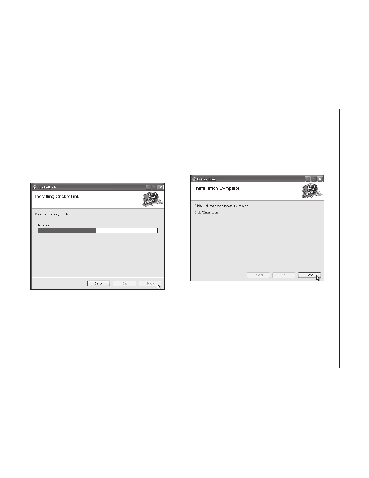
S TEP 3: During this step the components
of CricketLink product are being installed
onto your computer. Installation will occur
to the destination folder specified in Step
2 above.
S TEP 4: Installation of CricketLink is now
complete. Click the “Close” button to leave
the CricketLink setup program and begin
using your new software.
*
The setup program will automatically cre-
ate a CricketLink shortcut on your desktop.
Page 10
10
2. INSTALLATION AND SETUP FOR CRICkETLINk
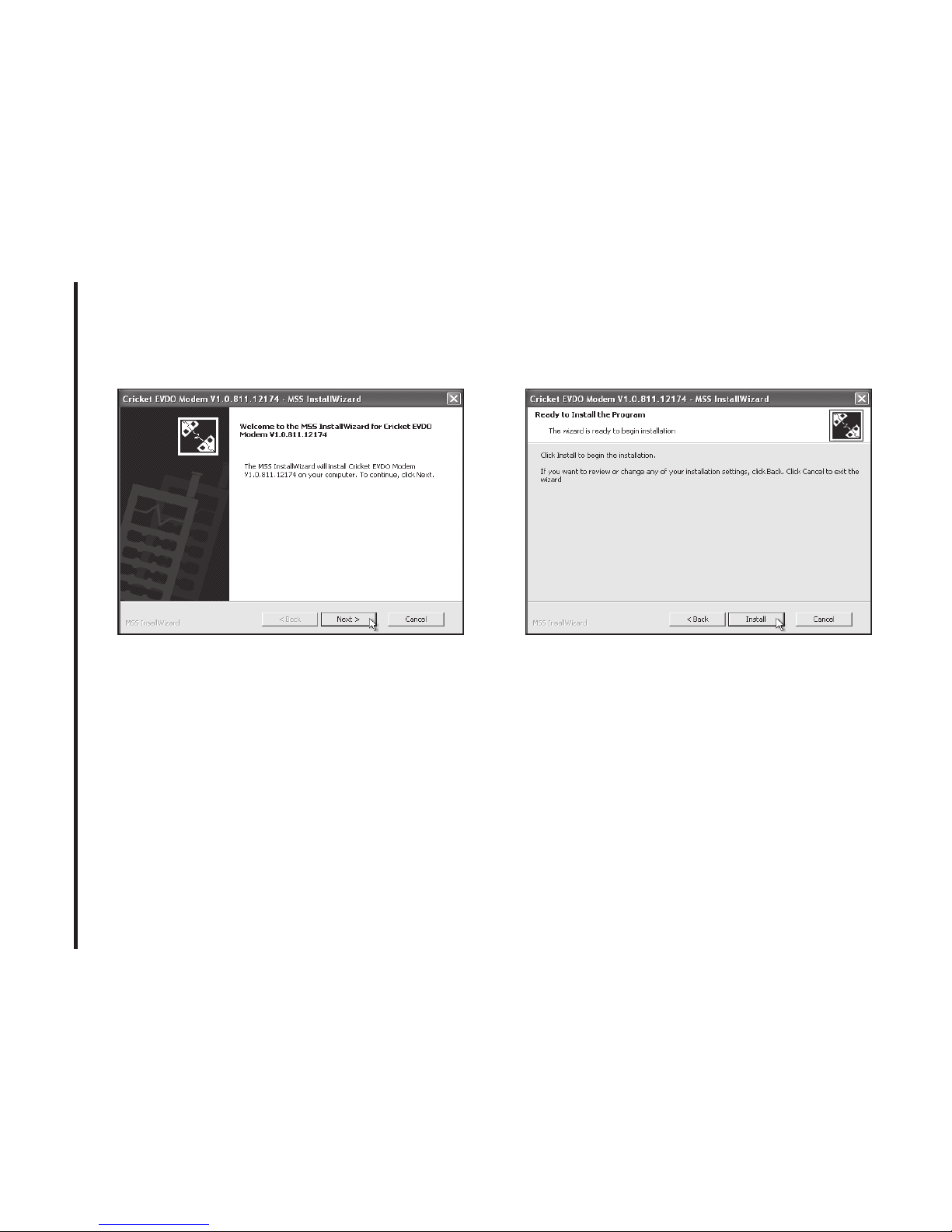
S TEP 5: Now the computer is installing
USB Driver. Click “Next” button.
S TEP 6: Click “Install” button to start
installation,.
Page 11
11
2. INSTALLATION AND SETUP FOR CRICkETLINk
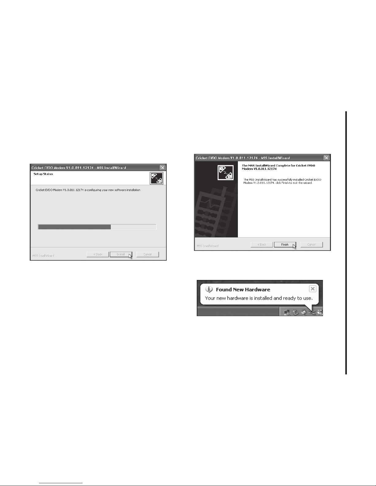
S TEP 7: During this step the components of
USB Driver are being installed onto your
computer. It takes a few minutes.
S TEP 8: Installation of USB Driver is now
complete. Click “Finish” button to leave.
S TEP 9: Please wait while A600 is installed
and ready to use.
Page 12
12
2. INSTALLATION AND SETUP FOR CRICkETLINk
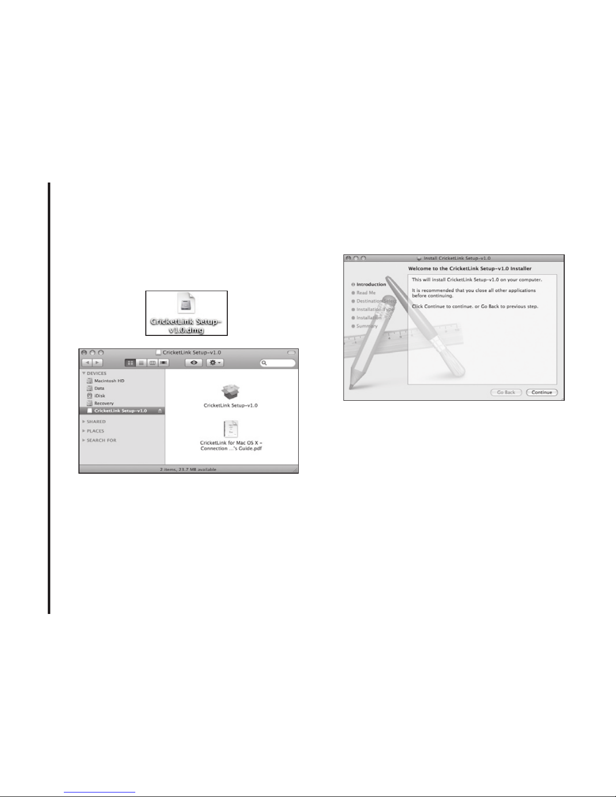
Setup Program - Mac OS X
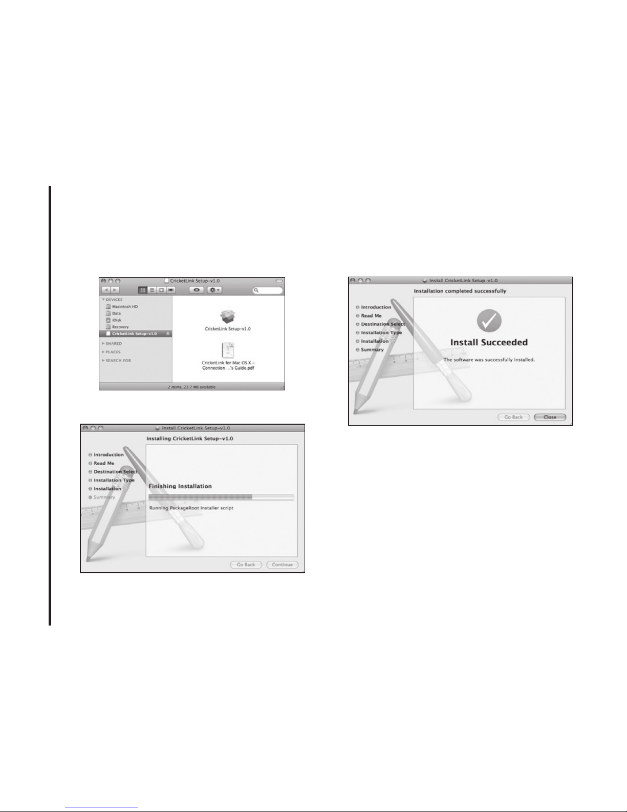
S TEP 1: To start installation, double click
icon of the Package program file.
S TEP 2: Click “Continue” > button in the
welcome window to continue installation.
Page 13
13
2. INSTALLATION AND SETUP FOR CRICkETLINk
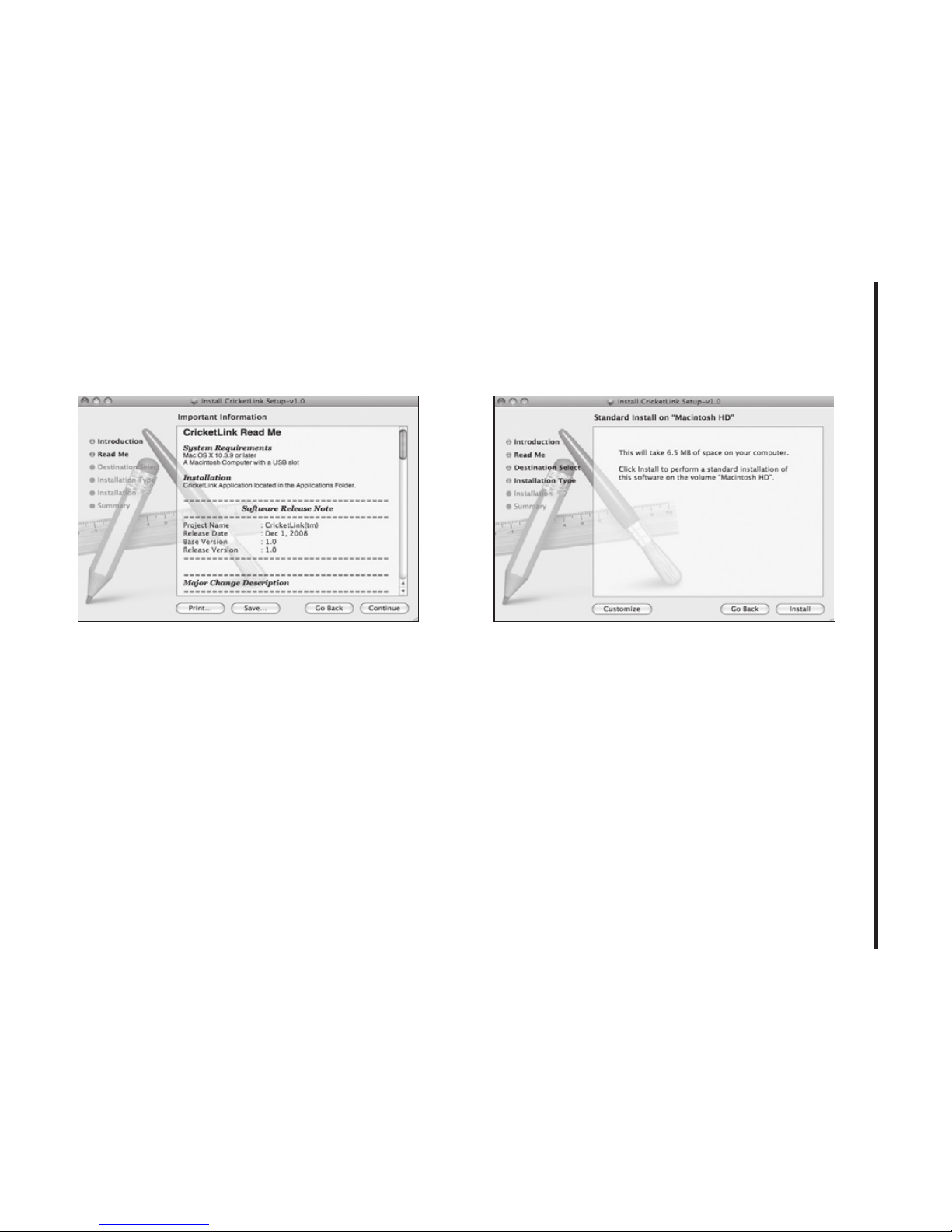
S TEP 3: The Read Me file appears. Click
the “Continue” button.
S TEP 4: Click Install to begin Standard
Install on system volume.
Page 14
14
2. INSTALLATION AND SETUP FOR CRICkETLINk
S TEP 5: Finally, Setup Wizard shows
confirm window, click “OK” > button to
continue.
S TEP 6: Installing CricketLink.
S TEP 7: Installation is now complete.
Click “Close” button to leave CricketLink
setup wizard.
Page 15

15
3. USING CRICkETLINk
Today’s online world offers more services
everyday and Wireless gives you the tools
you need to take advantage of the best in
connectivity solutions. With CricketLink,
enjoy the freedom and convenience of
wireless Internet connectivity from your
laptop computer!
Features
WWAN (Wireless Wide Area Network,
1xEV-DO/1xRTT/CDMA) Specific
Features:
• Congures your PC to use your USB
Modem.
• Creates a Data Connection if using an
EVDO capable USB Modem.
• Copies utility to create wireless copies of
your dial-up connections, if supported by
your device.
• Test function for WWAN device.
*
A WWAN capable device is required to
use the WWAN features. Individual WWAN
features are also device dependent as
described in the WWAN section above.
Other Features:
• Logs connections used, duration and
bytes sent and received.
• It also supports SMS messaging.
• See the section “Additional Features” for
more information about the features of
CricketLink.
Getting Started
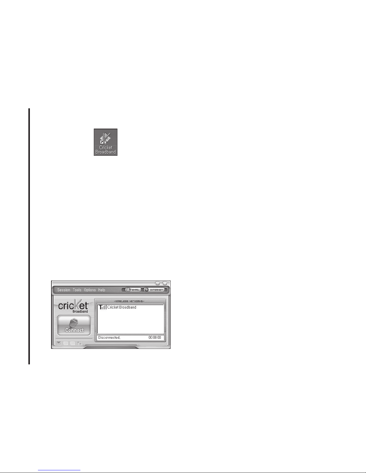
Double click on the Cricket Broadband icon
on your desktop or click on the Windows
Start menu and select CricketLink from the
list of Programs.
Page 16
16
3. USING CRICkETLINk
About the Wireless Networks View
CricketLink will open the Broadband Networks window by default. This view is where
you manage your Broadband connections.
The Broadband Networks window displays
all currently available network connections.
At a glance you can see the signal
strength .
Your current connection state and the
elapsed time of the connection are
displayed along the bottom of the status bar.
Connecting
Once your device is properly configured,
connecting to the Internet is as simple
as selecting the network connection type
shown in the list and clicking the “Connect”
button.
1. Select Data Connection.
2. Click the “Connect” button when it
becomes enabled.
Once connected, the “Connect” button will
change to “Disconnect”.
Simply click this to end your current connection. To connect to any other network
shown, select it, and then select “Connect”.
The Status Bar
Information regarding your current network
connection can be seen in the status bar
along the bottom of CricketLink interface.
Page 17
17
3. USING CRICkETLINk
For more information on this status bar,
see the section “The Status Bar” in the “Additional Features” section.
CricketLink will display status information at
the bottom during the connection process
as well as while connected. When not
connected, the status text in the lower left
corner will display “Not connected” for the
currently selected network. The timer will
display “00:00:00”. Once connected, the
status text will display “Connected” and the
elapsed timer will begin to run.
Right clicking on the tray icon provides
various options and double clicking on it will
always show the application. Placing your
cursor on it will display the current connection status.
Based on your preferences, your browser,
e-mail or VPN program can be launched
automatically, or you can launch whatever
software you want to use.
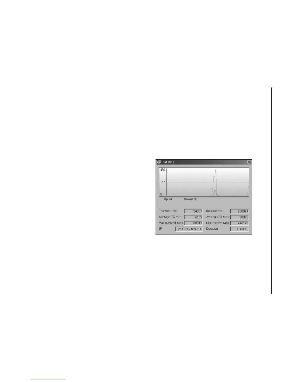
At any time during your connection you can
check your current connection speed and
throughput stats in the Statistics window. To
see this window, select “Statistics” from the
“Session” menu.
When using the “Data” connection:
By default CricketLink enables the software
for the Data connections.
Page 18
18
3. USING CRICkETLINk
If your connection fails when you try to
connect, with CricketLink returning to its idle
state, you should try to connect again.
Dormancy:
The data session becomes dormant if you
are not sending or receiving any data. As
soon as you resume sending or receiving
data, the data session will return to an
active state.
SMS Messaging
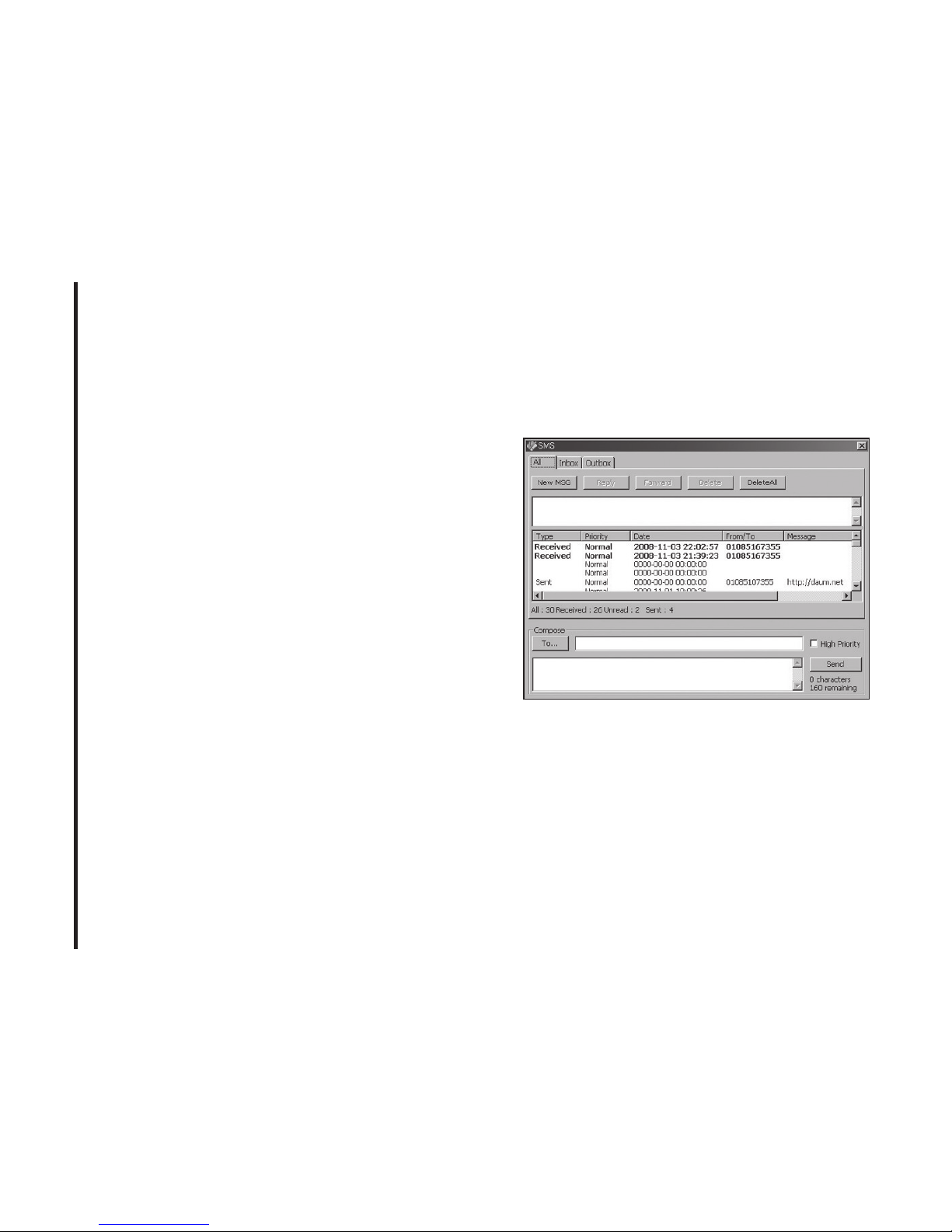
CricketLink supports SMS Messaging for
the A600.
Receiving SMS Messages
• All of your SMS messages will appear in
the list box at the top of the SMS messaging view. By default, all sent and received
messages will appear.
Page 19

19
3. USING CRICkETLINk
• To view only certain messages, click on
the message and select “All”, “Inbox” or
“Outbox”.
• If you are in the SMS Messaging view and
a new message arrives, the message will
automatically appear in the list formatted
in bold.
• To view a long SMS message, select the
message in the list view. The details of the
message will appear above the list.
• To reply to an inbound message, select
the message and press the “Reply” button.
The phone number of the sender will be
populated in the send area below. Enter
your new message and press the “Send”
button to send the message.
• To forward an inbound message, select the
message and press “Forward” button.
The message will be populated in the send
area below prefixed with a “FW:.” Press the
“Send” button to send the message.
Sending SMS Messages
• While using the A600, to send a text
message to:
— A US-based wireless number, enter:
+, 1, then the wireless number.
— A wireless number outside the US,
enter: +, 011, the country code, then the
wireless number.
• To send a SMS message to one or more
subscribers, enter their 10-digit mobile
numbers separated by semi-colons in
the “To...” field. (Ex: 555-555-5555; 555555-5556).
Page 20

20
3. USING CRICkETLINk
• With some devices that support SMS
messaging contact lists, you may be able
to click on the “To” button to open your
contact list.
• The phone number and the message
fields are required.
• The Character counter counts up from 0 to
150 and counts all of the characters typed
in the message field. (Spanish: 0~130)
• Click the “Send” button.
Page 21
21
4. CRICkETLINk PREFERENCES
General Preferences
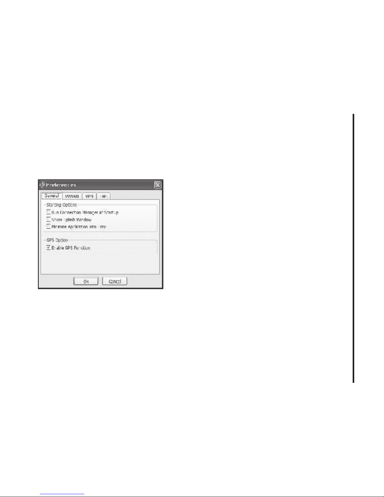
Click on “Options”, then “Preferences”.
General Tap
Run Connection Manager at Startup: If
this option is checked the CricketLink starts
automatically when Windows starts.
Show Splash Window: Display splash
window when Connection Manager starts.
Minimize Application into Tray: When you
minimize the application it will now appear
in the Windows task bar. To restore the application click on CricketLink tray icon, and
select “Open”.
Enable GPS Function: This option enables
or disables GPS functionality.
• Click the “Ok” button.
WWAN Specific Settings
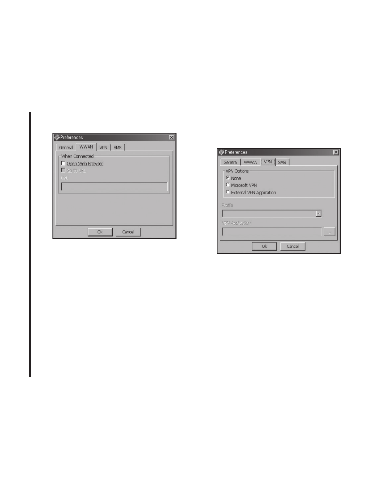
WWAN preferences
This is used to set various WWAN connection settings. See below.
Page 22
22
4. CRICkETLINk PREFERENCES
Open Web Browser: When data connection is established successfully,
CricketLink executes default Web-browser
automatically.
Go to URL: To enable web-browser go to
web site you defined using URL field below.
URL: Web site URL for starting page of web
browser started automatically.
• Click the “Ok” button.
VPN Settings
VPN Options
• None: Do not use VPN.
• Microsoft VPN: Use VPN client of Micro-
soft Windows.
• External VPN Application: Use other
VPN client application provided another
vendor.
Page 23
23
4. CRICkETLINk PREFERENCES
Profile (Microsoft VPN only)
Select Microsoft VPN Profile.
External VPN Application
Specify other VPN client application. To
choose the application from your local disk,
click “
” button.
• Click the “Ok” button.
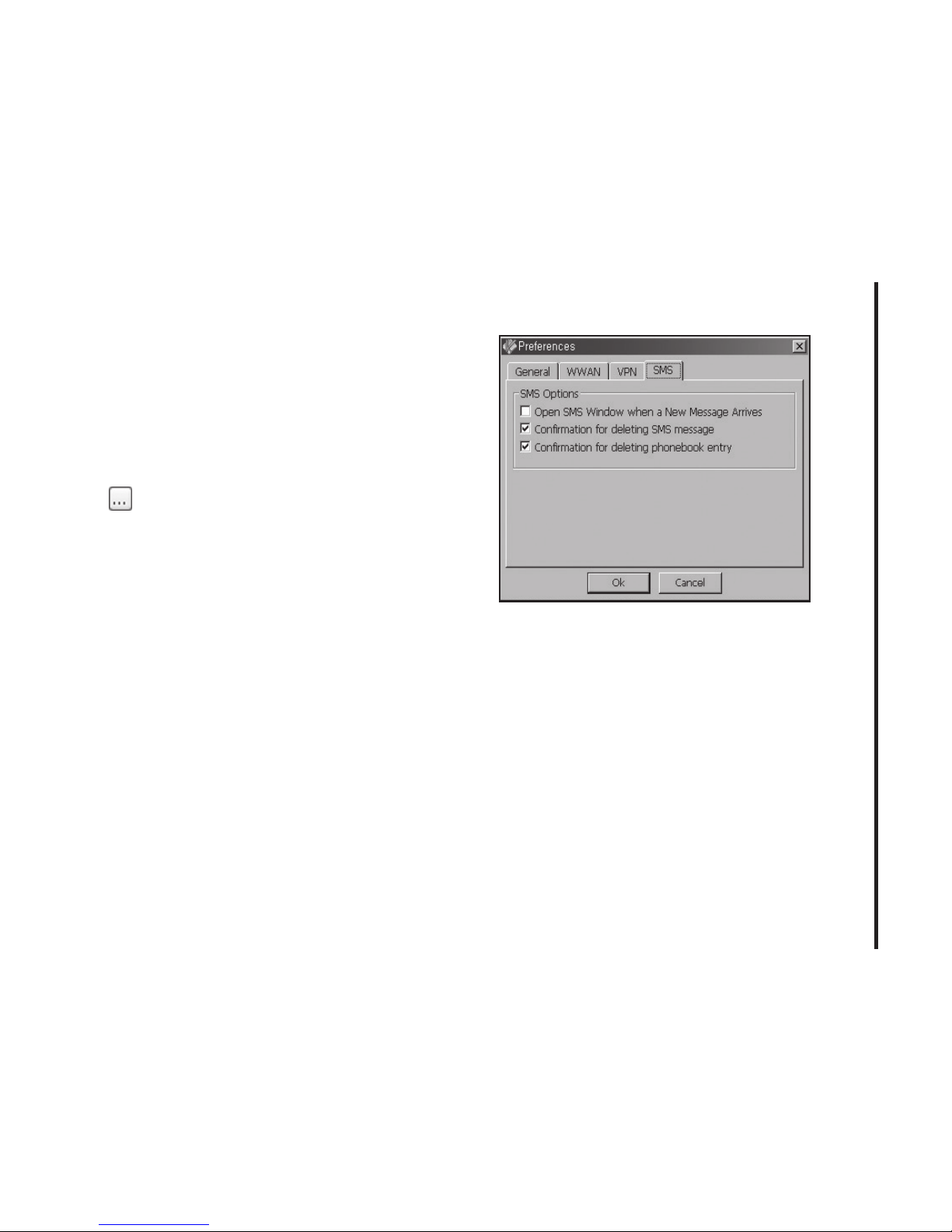
SMS Settings
SMS (Short Text Message Service) is a
messaging application for your wireless device which allows you to compose and send
text messages to other wireless phones.
The SMS tab in the preferences dialog allows you to configure certain text message
delivery options. These options include:
Incoming Message Options
• Open SMS Window when a New Message Arrives: Enable/disable automatic
opening of the SMS window on arrival of
new text messages.
• Confirmation for deleting SMS message: Confirm deletion of messages.
• Confirmation for deleting phonebook
entry: Confirm deletion of phonebook
entry.
Page 24
24
4. CRICkETLINk PREFERENCES
• Click the “Ok” button.
Additional Features
In addition to the basic features mentioned
in previous sections, CricketLink has the
additional features listed below.
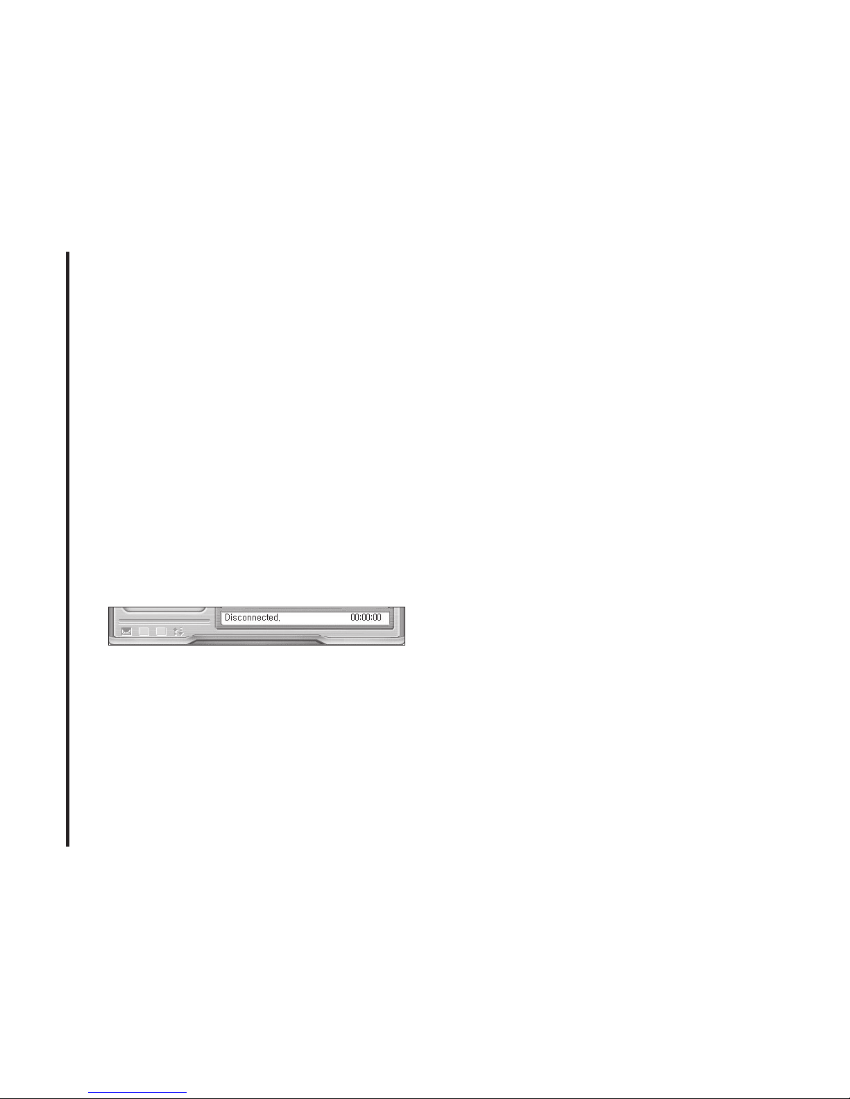
The Status Bar
The details of your current connection can
be seen in the status bar at the bottom
of CricketLink interface. This status bar is
always visible when the interface is fully
expanded.
Connection Status
The text on the status bar reflects your
current state. During an active connection,
this text will change to “Connected”. If you
are not connected, it will display “Disconnected”.
WWAN USB Modem Status Area
The text can change to the following:
• No Device: Your WWAN USB Modem is
removed from the laptop.
• Device not activated: Your USB Modem
needs to be activated. Select “Activation”
from the Tools menu.
Throughput
The amount of data that you have sent and
received since the current network connection was initiated can be seen by holding
the mouse over the green up and down
arrows on the left side of the status bar.
Elapsed Time
The amount of time that has elapsed
since the current network connection was
initiated is tracked on the lower left side of
the status bar.
Page 25
25
4. CRICkETLINk PREFERENCES
The Session Menu
Connect / Disconnect: You can connect or
disconnect the wireless networks.
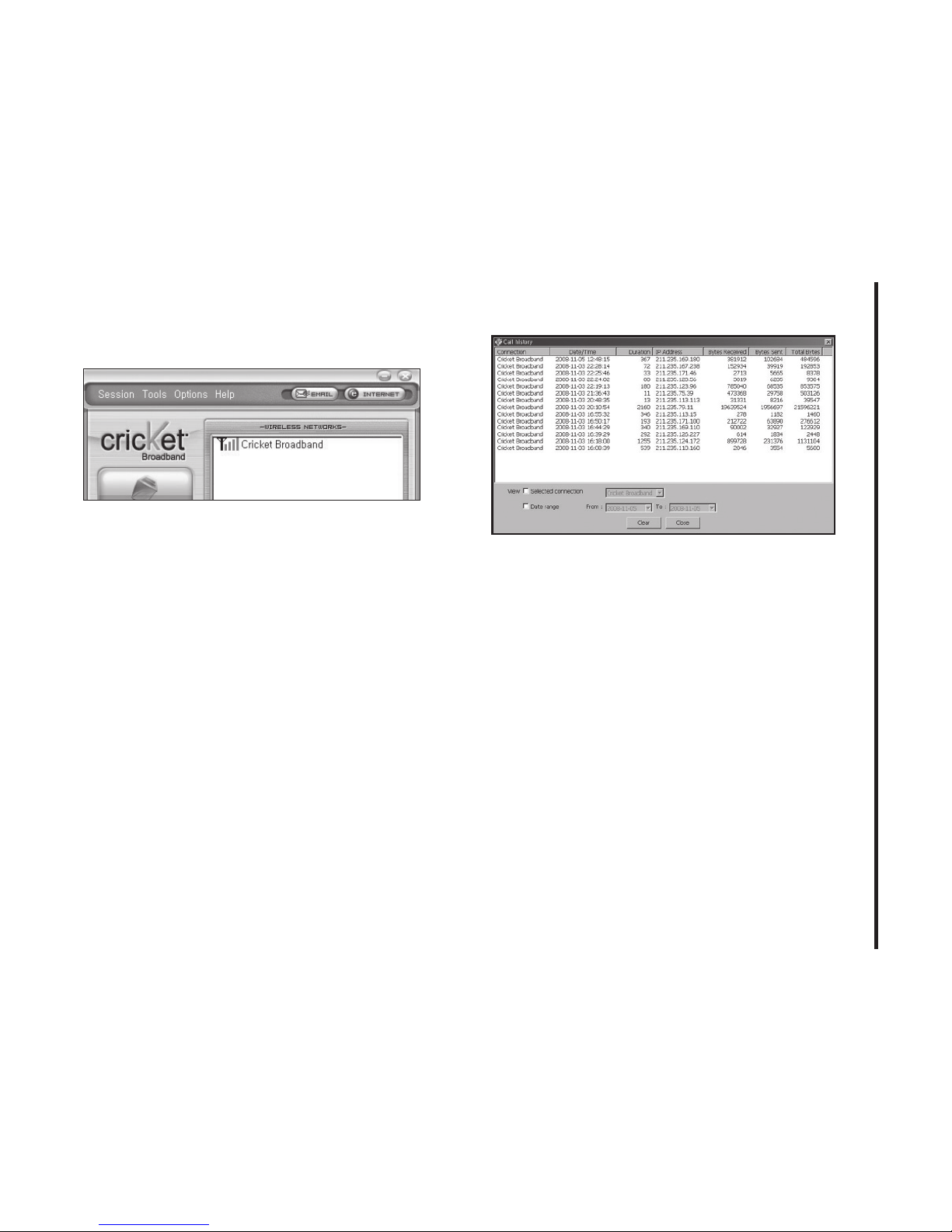
Log: This provides a concise session log
of your network activity. Click on a column
heading to sort the log. This window also
displays the total number of sessions as
well as the total time connected.
The information displayed in the Usage log
can be customized using the controls that
appear just below the list.
To view only the connection history of a
specific network type, check the “Selected
connection” checkbox and select the desired
type from the drop-down list.
To view only the connections made during
a specific interval, check the “Date range”
checkbox and specify the date in the “From:”
and “To:” fields.
To clear the log, press the Clear button.
Note that clearing the log cannot be undone.
Close: Close the log window.
Page 26
26
4. CRICkETLINk PREFERENCES
The Tools Menu
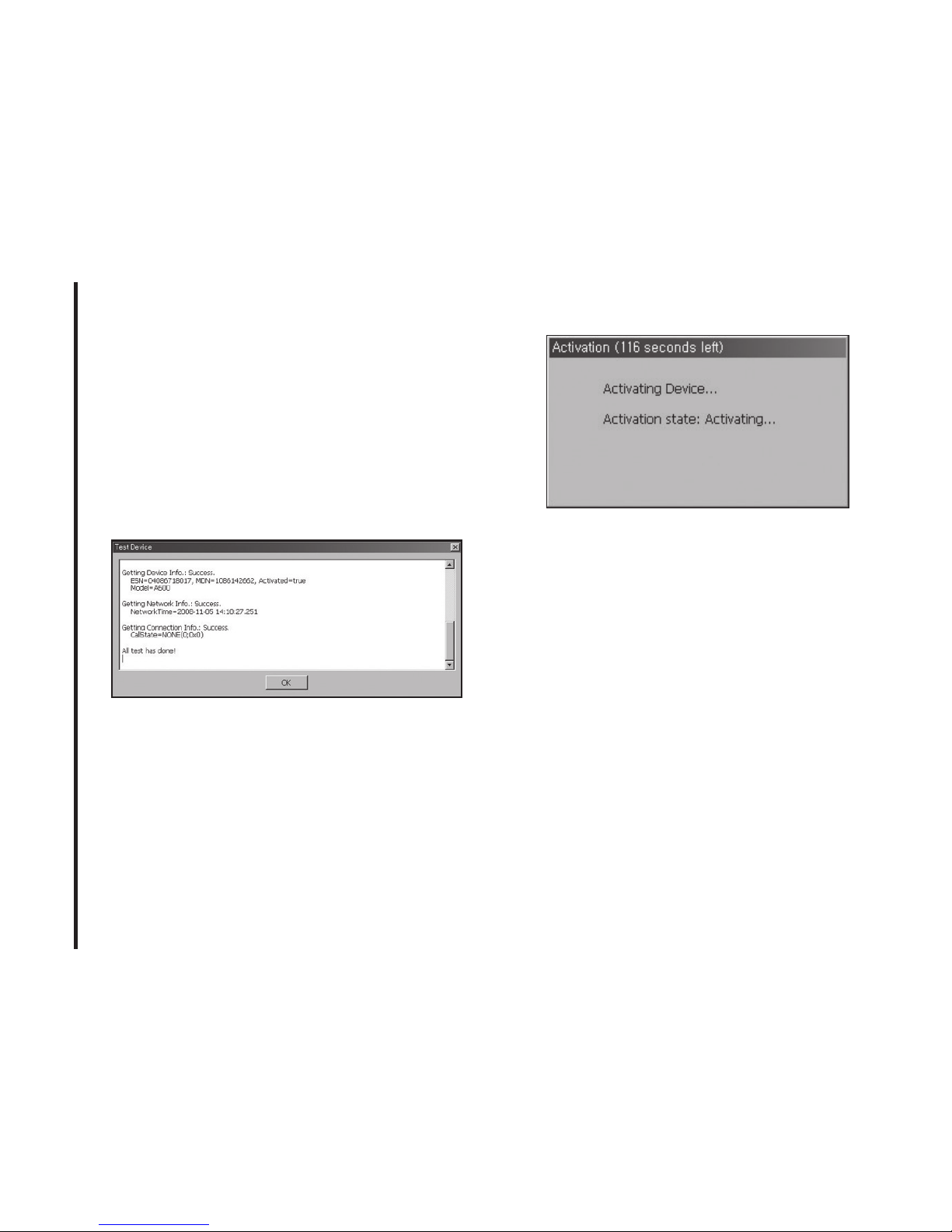
Test WWAN Device: Retrieve and display
detailed information about your WWAN
device (1xEV-DO/1xRTT/CDMA USB Modem) such as manufacturer, model, version,
etc. This information can be valuable when
troubleshooting a problem.
Find Device: Find your modem device
again. This is useful if you need to reconfigure CricketLink to use a new USB Modem.
Activation: Programs the activation code,
phone number, and IMSI(MIN) to the USB
Modem.
The Options Menu
Preferences: This is used to select preferences for connection settings. Please see
WWAN Specific Settings for details.
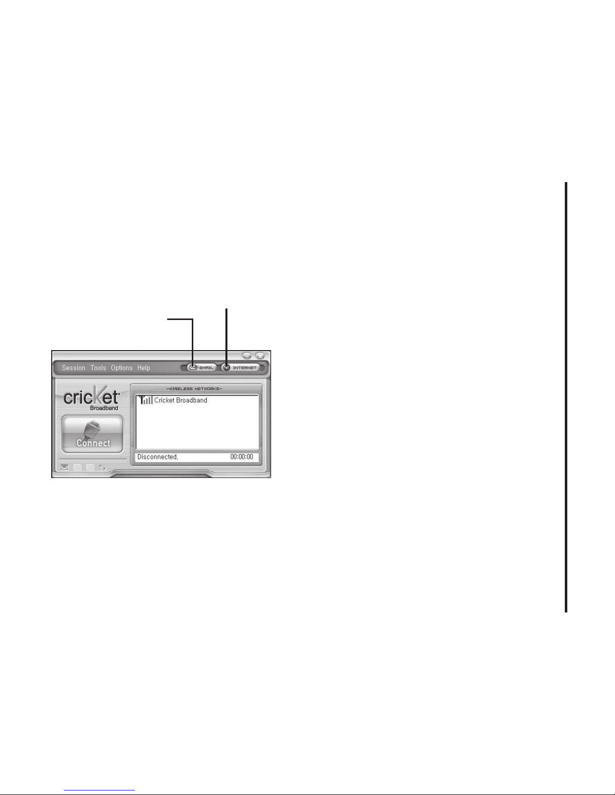
The “Internet” button
Launches the default web browser on your
computer.
The “Email” button
Launches the default email application on
your computer.
Page 27
27
4. CRICkETLINk PREFERENCES
The Help Menu
The Connection Manager has a Help
section. Please see the Help section for
additional questions.
“Email” Button
“Internet” Button
Page 28
28
5. INSTALLING A600
Recommended System
Requirements
To successfully install and use the A600
USB device in your PC, the following
system specifications are required.
Item Required Specification
Operating
system
Windows® Vista / Win-
dows® XP /
Windows® 2000
Mac OS X 10.3.9
or higher
Port Type A USB port
Processor 150MHz or faster
Memory 128 MB
Disk space 32 MB
Dial-up
networking
DUN bound to TCP/IP
*
The A600 is useful for laptop PCs that
include a USB port. Voice service is not
supported.
Installing Software
Warnings
• Make sure to complete the unplugging/
ejection process before removing the
A600. If you remove the device improperly,
the product may be damaged.
Notes
• If you have inserted the device properly,
Windows will inform you of the new hardware. Wait until Windows completes the
“Found New Hardware” task.
Page 29
29
5. INSTALLING A600
In Windows 2000, several windows similar
to “Found New Hardware” window can
appear and disappear automatically. In
Windows XP, several tool tips similar to
the “Found New Hardware” function will
appear and disappear in the system tray
automatically. In Windows Vista, several tool
tips similar to the “Installing device driver
software” function will appear and disappear
in the system tray automatically. Once
hardware detection is complete, you will be
prompted to start activation.
• It is normal to hear a short beep sound
each time you insert or remove the A600.
It is an audible notification that your PC
recognizes the new hardware.
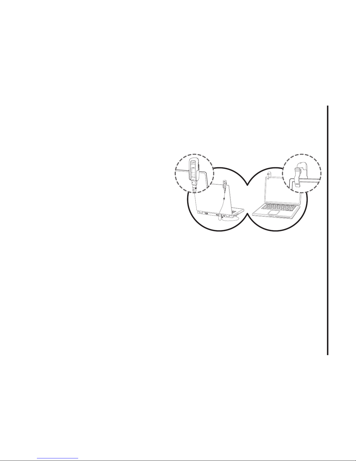
• The A600 comes with a convenience clip
to attach to your laptop computer when
the screen is in the upright position. This
will help deliver optimum reception, as well
as allow easy monitoring of the LED status
indicators while in use.
Page 30
30
5. INSTALLING A600
Using the Device
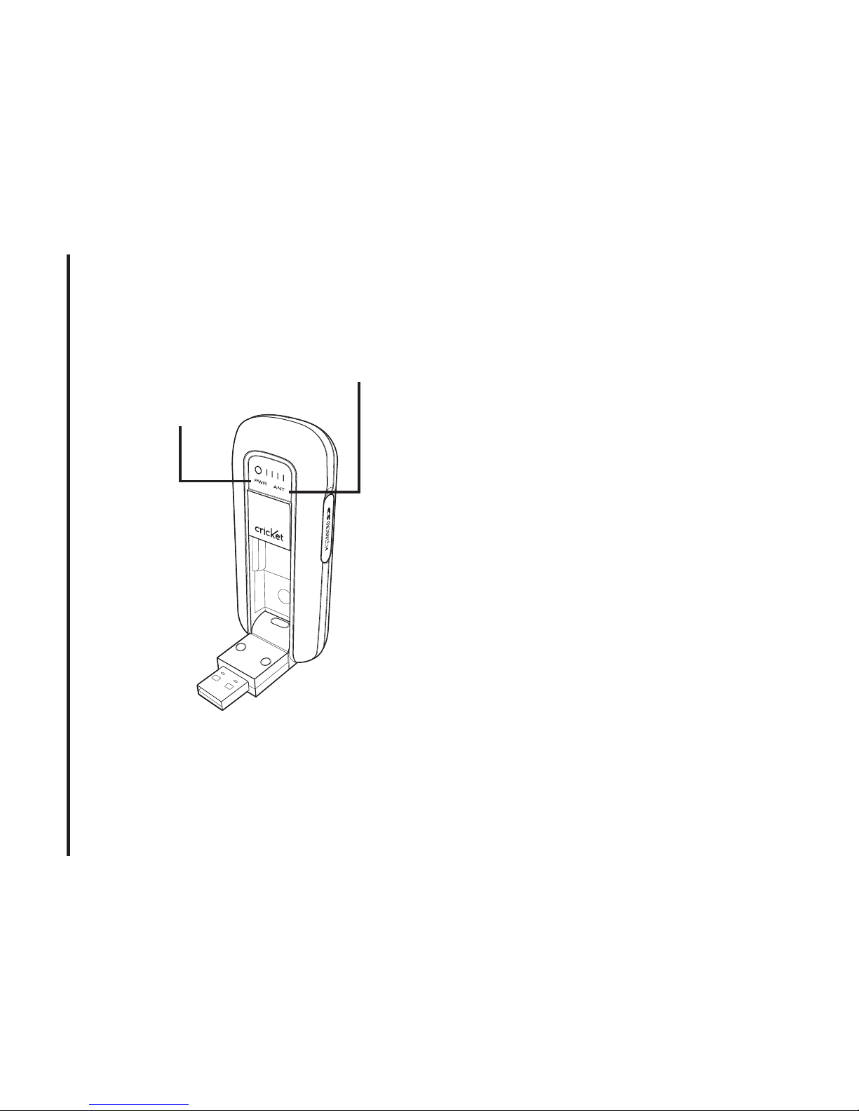
Power statue LED
• Green: Power OK.
• Red: Not enough power. If you see Red
on the power status LED it is recommend
that you use the USB modem extension
Y cable.
Signal strength indicator
• 0~4: Weak or no signal strength, 4: high
signal strength.
Note: Make sure to complete the unplug-
ging/ejection process before removing the
A600. If you remove the device improperly,
the product may be damaged.
Unplugging or Ejecting the
modem
• Make sure to complete the unplug/eject
process on your computer before removing
the A600 from your PC. If you remove the
USB device improperly, the product may
be damaged.
Power status LED
Signal strength indicator
Page 31
31
5. INSTALLING A600
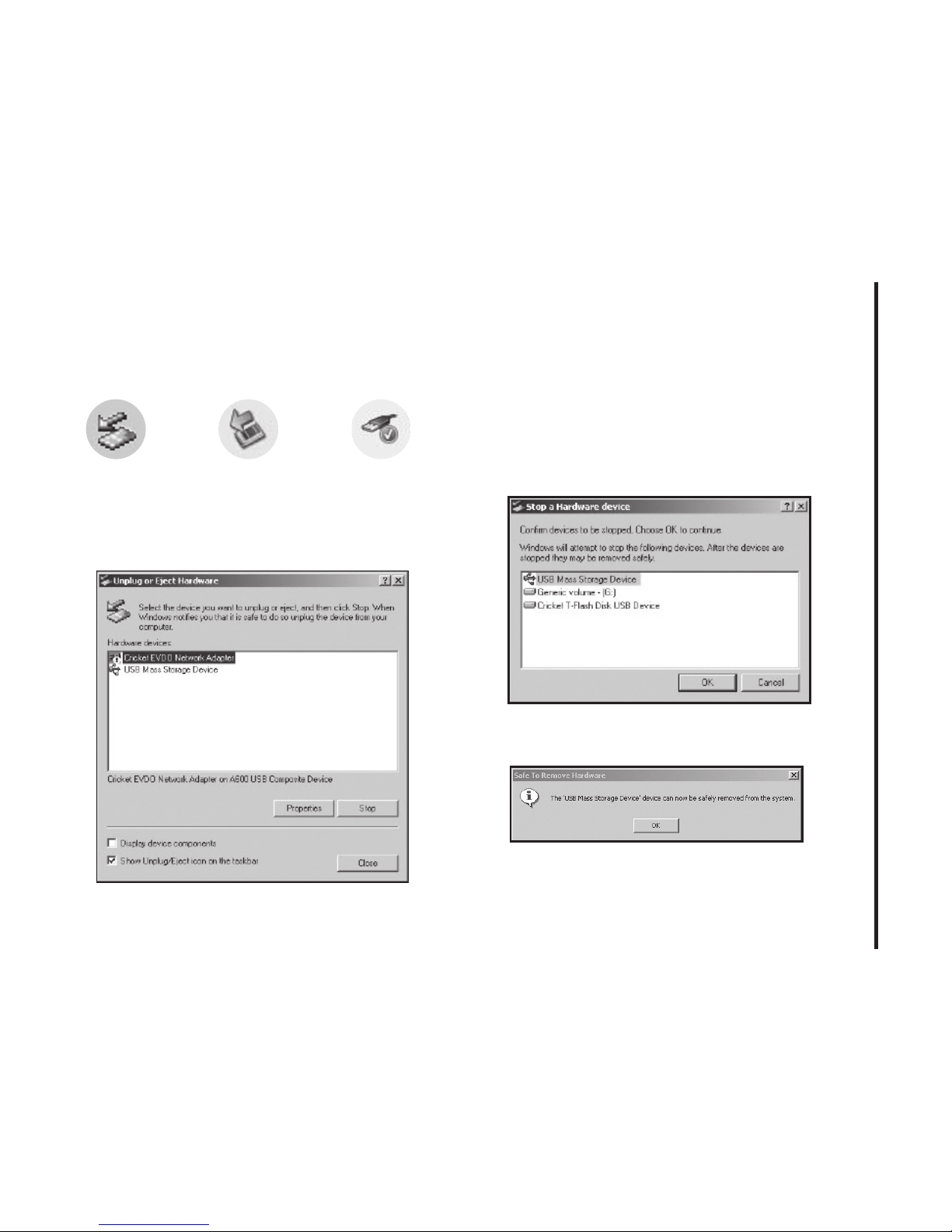
• Double click the Unplug/Eject Hardware
icon in the system tray.
1) Unplug or Eject Hardware with Windows
2000
• As shown in the above gure, “Cricket
EVDO Network Adapter” or “USB Mass
Storage Device” options will be displayed
in the Hardware devices list of Win2000.
Select the “USB Mass Storage Device”
and click the “Stop” button.
• Select either of the “USB Mass Storage
Device” and click the [OK] button.
• The dialog box above will appear. Click the
[OK] button.
Windows 2000 Windows XP
Windows Vista
Page 32
32
5. INSTALLING A600
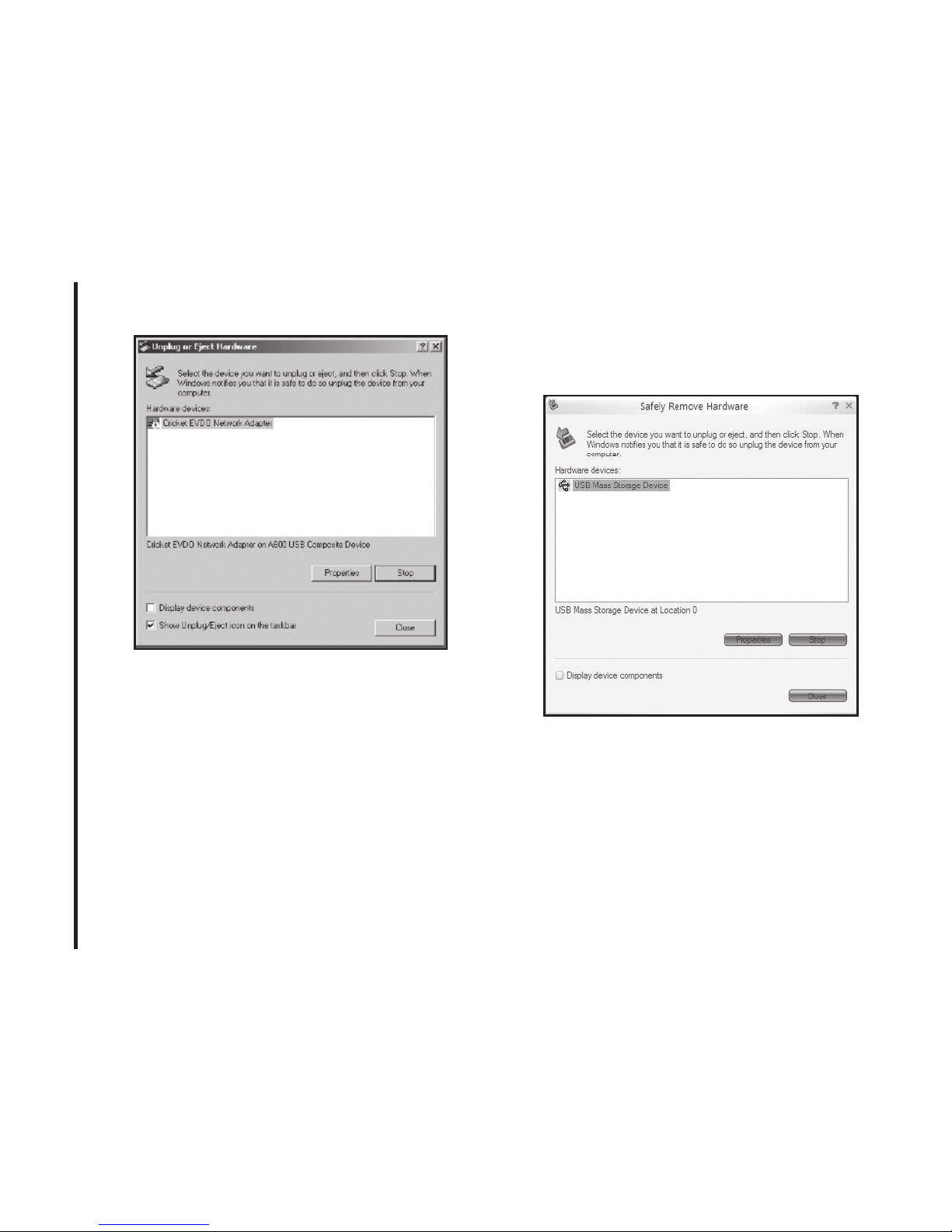
• Then, the above window will appear. It is
now safe to unplug the A600.
2)
Unplug or Eject Hardware with Windows
XP
• As shown above, only one “USB Mass
Storage Device” option will be displayed in
Windows XP. Select “USB Mass Storage
Device” and click the “Stop” button.
Page 33

33
5. INSTALLING A600
• Then, “USB Mass Storage Device” and
click the [OK] button.
• Click the [Close] button. It is now safe to
unplug the A600.
Page 34
5. INSTALLING A600
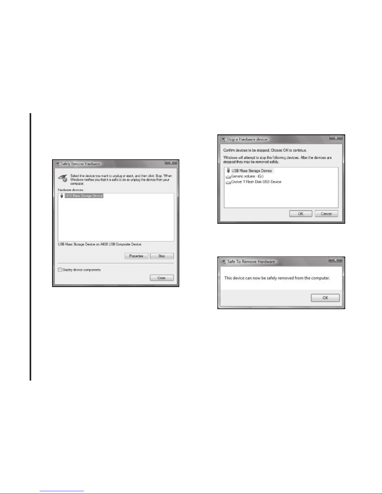
3) Unplug or Eject Hardware with Windows
Vista
• As shown above, only one “USB Mass
Storage Device” option will be displayed in
Windows Vista. Select “USB Mass Storage
Device” and click the “Stop” button.
• Then, two “USB Mass Storage Device”
and click the [OK] button.
• The dialog box above will appear. Click the
[OK] button.
34
Page 35
35
5. INSTALLING A600
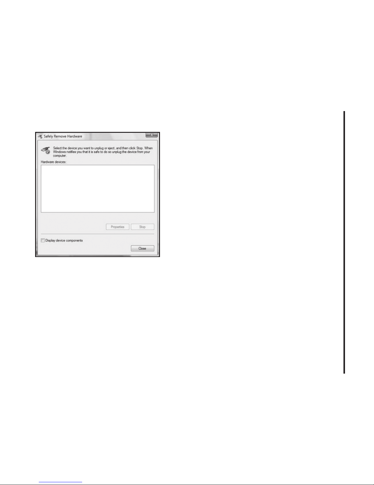
• Click the [Close] button. It is now safe to
unplug the A600.
Page 36

36
5. INSTALLING A600
Remove the A600 from your
laptop
• Remove the A600 from your laptop. When
removing the A600, always grip the sides
of the modem and push/pull carefully.
Using the USB Modem
Extension Y Cable
• The A600 Modem package includes an
extension USB Y-shaped cable. Although
the Y cable is not required for use with
your A600 Modem, it offers increased
performance for your A600 Modem under
certain operating conditions. Connect the
Y cable to two separate USB ports of your
computer to deliver sufficient power when
needed to increase RF performance, and
to solve clearance issues.
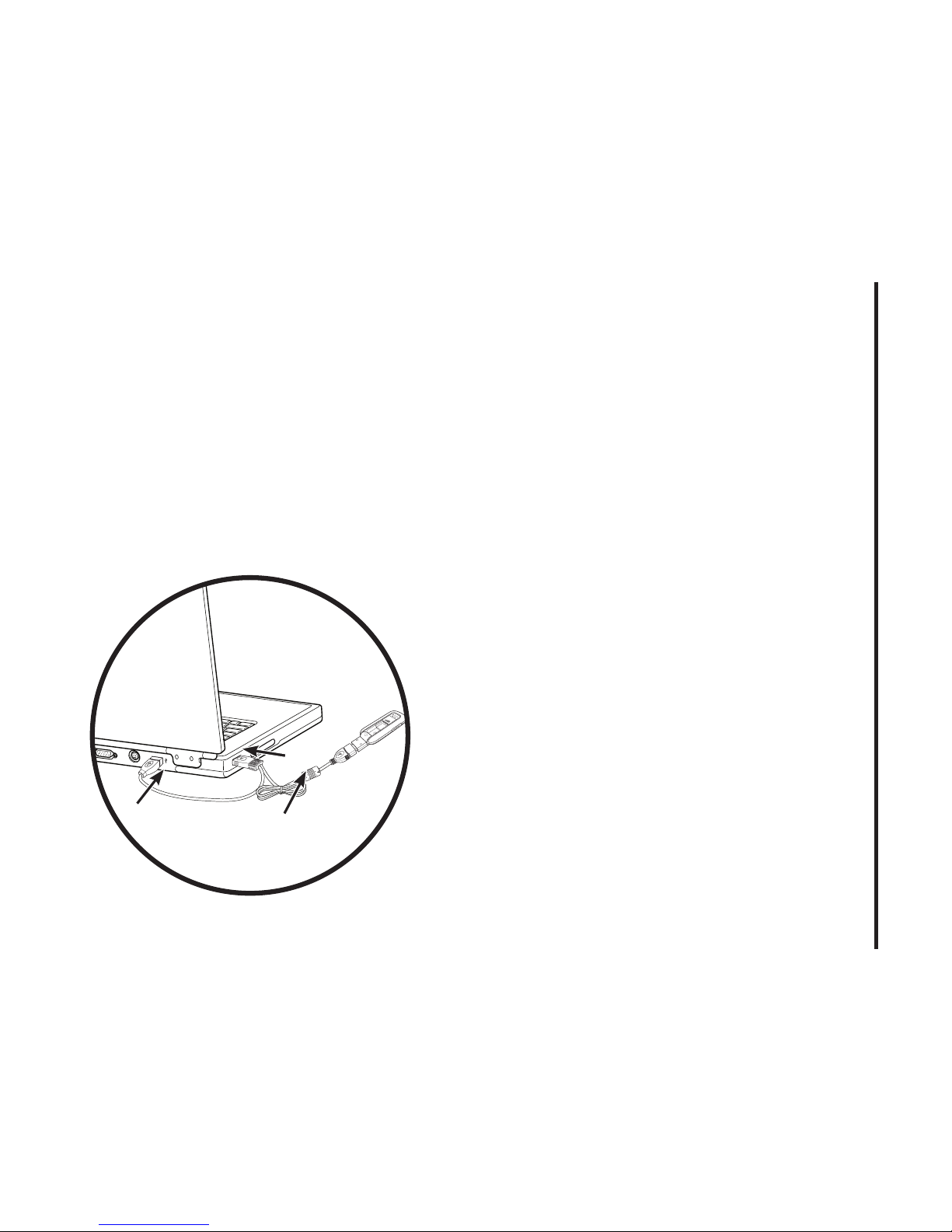
Using the USB Modem Extension Y
Cable:
1) Plug the single end of the Y-shaped cable
into the A600 Modem. [A]
2) Depending on the condition you are trying to solve (increased RF performance,
or clearance issues), plug either one
of the two connected ends of the USB
modem extension Y cable into the Type A
USB port(s) on your computer. [B]
Note: The USB modem extension Y cable
connector labeled #1, is the primary data
power cable used to either extend the A600
modem away from your computer allowing
you to locate the modem in a more optimum
signal location or solve any computer USB
port clearance issues. The USB modem
extension Y cable connector labeled #2, is
a power boost Y cable and must be used
with connector #1 to provide the modem up
Page 37
37
5. INSTALLING A600
to 1Amp of current for use in weaker signal
areas. Must be connected to two separate
USB ports.
3) The device is connected to and powered
by the computer as soon as the USB Y
cable is plugged properly into the
appropriate Type A USB port(s).
4) Click Connect.
B
A
#1
B
#2
Page 38

38
CARE AND MAINTENANCE
CARE AND MAINTENANCE
Your device is a product of superior design
and craftsmanship and should be treated
with care. The suggestions below will help
you protect your warranty coverage.
• Keep the device dry. Precipitation, humidity and all types of liquids or moisture
can contain minerals that will corrode
electronic circuits.
• Do not use or store the device in dusty,
dirty areas. Its moving parts and electronic
components can be damaged.
• Do not store the device in hot areas.
High temperatures can shorten the life of
electronic devices, damage batteries, and
warp or melt certain plastics.
• Do not store the device in cold areas.
When the device returns to its normal
temperature, moisture can form inside
the device and damage electronic circuit
boards.
• Do not attempt to open the device.
• Do not drop, knock, or shake the device.
Rough handling can break internal circuit
boards and fine mechanics.
• Do not use harsh chemicals, cleaning
solvents, or strong detergents to clean
the device.
• Do not paint the device. Paint can clog
the moving parts and prevent proper
operation.
• Use only the supplied or an approved
replacement antenna. Unauthorised
antennas, modifications, or attachments
could damage the device and may violate
regulations governing radio devices.
Page 39

39
SAR INFORMATION
All of the above suggestions apply equally
to your device, battery, charger, or any
enhancement. If any device is not working
properly, take it to the nearest authorized
service facility for service.
SAR INFORMATION
THIS MODEL PHONE MEETS THE
GOVERNMENT’S REQUIREMENTS FOR
EXPOSURE TO RADIO WAVES.
Your wireless phone is a radio transmitter
and receiver. It is designed and manufactured not to exceed the emission limits for
exposure to radiofrequency (RF) energy set
by the Federal Communications Commission of the U.S. Government. These limits
are part of comprehensive guidelines and
establish permitted levels of RF energy for
the general population. The guidelines are
based on standards that were developed
by independent scientific organizations
through periodic and thorough evaluation
of scientific studies. The standards include
a substantial safety margin designed to
assure the safety of all persons, regardless
of age and health. The exposure standard
for wireless mobile phones employs a unit
of measurement known as the Specific
Absorption Rate, or SAR. The SAR limit
set by the FCC is 1.6 W/kg. * Tests for SAR
are conducted with the phone transmitting
at its highest certified power level in all
tested frequency bands. Although the SAR
is determined at the highest certified power
level, the actual SAR level of the phone
while operating can be well below the
maximum value. This is because the phone
is designed to operate at multiple power
levels so as to use only the power required
to reach the network. In general, the closer
you are to a wireless base station antenna,
Page 40

40
SAR INFORMATION
the lower the power output. Before a phone
model is available for sale to the public, it
must be tested and certified to the FCC that
it does not exceed the limit established by
the government adopted requirement for
safe exposure. The tests are performed in
positions and locations (e.g., at the ear and
worn on the body) as required by the FCC
for each model. The highest SAR value for
this model modem when tested for use near
the body, as described in this user guide, is
1.16 W/Kg. While there may be differences
between the SAR levels of various phones
and at various positions, they all meet the
government requirement for safe exposure.
The FCC has granted an Equipment
Authorization for this model phone with all
reported SAR levels evaluated as in compliance with the FCC RF exposure guidelines.
SAR information on this model phone is on
file with the FCC and can be found under
the Display Grant section of http://www.fcc.
gov/ oet/fccid after searching on FCC ID:
US7-A600. Additional information on Specific Absorption Rates (SAR) can be found
on the Cellular Telecommunications Industry
Asso-ciation (CTIA) web-site at http://www.
wow-com.com. * In the United States and
Canada, the SAR limit for mobile phones
used by the public is 1.6 watts/kg (W/kg)
averaged over one gram of tissue. The
standard incorporates a sub-stantial margin
of safety to give additional protection for the
public and to account for any variations in
measurements.
SAFETY INFORMATION
SAFETY INFORMATION FOR FIXED
WIRELESS TERMINALS POTENTIALLY
EXPLOSIVE ATMOSPHERES
Turn your phone OFF when in any area with
Page 41

41
SAFETY INFORMATION
a potentially explosive atmosphere and obey
all signs and instructions. Sparks in such
areas could cauls e an explosion or fire
resulting in bodily injury or even death.
INTERFERENCE TO MEDICAL DIVICES
Certain electronic equipment may be
shielded against RF signal from you wireless phone. (pacemakers, Hearing Aids,
and so on) Turn your phone OFF in health
c are facilities when any regulations posted
in these areas instruct you to do so. RF
signals may affect improperly installed or
inadequately shielded electronic system in
motor vehicles.
EXPOSURE TO RF ENERGY
Use only the supplied or an approved
replacement antenna. Do not touch the
antenna unnecessarily when the phone is
in use. Do not move the antenna close to,
or couching any exposed part of the body
when making a call.
NEAR BODY OPERATION
This device was tested for typical near body
operations with the back of the phone kept
0.5 cm from the body. To maintain compliance with FCC RF exposure requirements,
it must have a minimum distance including
the antenna of 0.5 cm from the body during
normal operation
FCC COMPLIANCE
INFORMATION
This device complies with Part 15 of FCC
Rules. Operation is subject to the following two conditions:
(1) This device may not cause harmful
interference, and
Page 42

42
FCC COMPLIANCE INFORMATION
(2) This device must accept any interference
received. Including interference that may
cause undesired operation.
U.S.A.
U.S.FEDERAL COMMUNICATIONS COMMISSION RADIO
FREQUENCY INTERFERENCE
STATEMENT
INFORMATION TO THE USER
NOTE : This equipment has been tested
and found to comply with the limits for a
Class B digital device pursuant to Part 15 of
the FCC Rules. These limits are designed
to provide reasonable protection against
harmful Interference in a residential installation This equipment generates, uses, and
can radiate radio frequency energy and, if
Not installed and used in accordance with
the instructions, may cause harmful Interference to radio communications. However,
there is no guarantee that interference will
not occur in a particular Installation. If this
equipment does cause harmful interference
to radio or television reception, which can
be determined by turning the equipment
off and on, the user is encouraged to try to
correct the interference by one or more of
the following measures:
*- Reorient or relocate the receiving an-
tenna. Increase the separation between
the equipment and receiver.
*- Connect the equipment into an outlet of
a circuit different from that to which the
receiver is connected.
*- Consult the dealer or an experienced
radio/TV technician for assistance.
Page 43

43
U.S.A. U.S.FEDERAL COMMUNICATIONS ...
Changes or modification not expressly
approved by the party responsible for
Compliance could void the user’s authority
to operate the equipment. Connecting of
peripherals requires the use of grounded
shielded signal cables.
Page 44

44
MEMO
 Loading...