

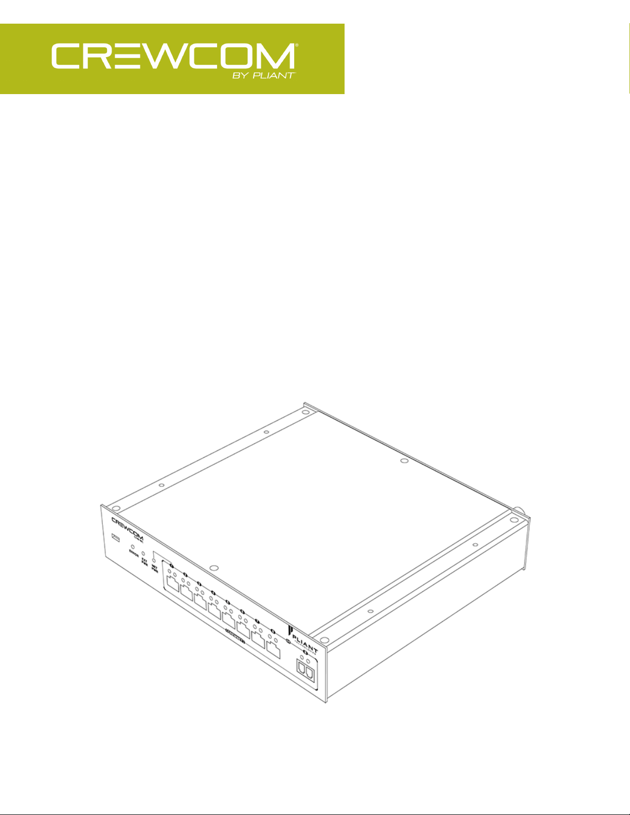
Hub
OPERATING MANUAL

- ii

THANK YOU
We at Pliant®Technologies want to thank you for purchasing CrewCom®. Pliant brings our experience, expertise,
and commitment to quality technology with the new CrewCom System. In order to get the most out of your new
CrewCom product, please take a few moments to read this manual completely so that you better understand the
operation of this product. For questions not addressed in this manual, feel free to review the additional support
documentation provided on our website or to contact Pliant’s Customer Support Department:
Pliant Technologies, LLC
205 Technology Parkway Auburn, AL 36830 USA
www.plianttechnologies.com
Phone: +1.334.321.1160
Toll-Free: 1.844.475.4268 or 1.844.4PLIANT
Fax: +1.334.321.1162
Copyright © 2018–2020 Pliant Technologies, LLC. All rights reserved. The Pliant®, CrewCom®, and CrewNet™word
marks and the Pliant “P” logo are trademarks of Pliant Technologies, LLC. Any and all other trademark references
within this document are property of their respective owners.
While Pliant makes every attempt to maintain the accuracy of the information contained in this manual, this
information is subject to change without notice, and published device/system functions and features are subject to
firmware version. Please check our website for the latest system specifications and certifications.
Model Information
This document applies to model CHB-8C, CHB-8C-02, and CHB-8F.
Document Reference: 2020.04 D0000217_H
Thank You - iii

TABLE OF CONTENTS
Thank You iii
Model Information iii
Table of Contents iv
Safety Information 1
Hub Safety Information 2
Safe Operation Recommendations 2
Safe Installation Recommendations 3
Power Information 3
Introduction 5
What's in the Box? 6
Firmware Release Notes 8
CrewCom Overview 9
Decentralized Network Architecture 9
Flexible RF Platform 9
Intuitive User Experience 9
CrewCom Devices 10
CrewWare 11
CrewCom Configuration File (CCF) 12
CrewCom Configuration File Defaults 12
Determining Which CCFis Active 12
Conferences 13
Profiles 13
Power Over CrewNet 15
What is Power-over-CrewNet? 15
Powering Downstream Devices 15
Table of Contents - iv

Product Overview 17
Hub 18
Copper Hub 19
Fiber Hub 21
Setup and Installation 23
Determine if you have a CCF. 24
Position Devices 25
How to Install Hubs 25
Connect to CrewNet 26
How to Connect CrewNet to Hubs 26
Hub Layers 27
Power On the System 28
How to Power On and Configure the System 28
Name a Device 29
Operation 30
Add More CrewCom Devices 31
Hub LEDs 32
Product Specifications 33
Hub Specifications 34
Product Support 35
Product Support 36
Returning Equipment for Repair or Maintenance 36
System Maintenance and Storage 37
System Maintenance and Storage 38
Cleaning 38
Temperature and Humidity 38
Table of Contents - v

License and Compliance Information 39
License Information 40
Warranty Information 41
Warranty Information 42
Limited Warranty 42
Parts Limited Warranty 43
Table of Contents - vi

CHAPTER 1
SAFETY INFORMATION
This chapter consists of the following sections:
Hub Safety Information 2
Safe Operation Recommendations 2
Safe Installation Recommendations 3
Power Information 3
Safety Information - 1
Hub Safety Information
WARNING: Indicates a situation, which, when not avoided, has the potential to result in death or
severe injury.
CAUTION: Indicates a situation, which, when not avoided, has the potential to result in minor injury or
product failure or damage.
The following section details important safety information related to the ownership and operation of the CrewCom
Hub.
1. Read these instructions.
2. Follow all instructions.
3. Heed all warnings.
Safe Operation Recommendations
l Install and operate in accordance with manufacturer’s instructions.
l Do not submerge the Hub in water.
l Do not set food, water, or other beverage containers on or near the unit.
l Do not place unit in areas where it will be exposed to weather.
l Ensure the device’s cord remain free from areas of foot traffic. Do not allow cords to become crimped, twisted,
or frayed.
l Clean only with a dry cloth. Do not spray household cleaners or water onto the cloth. Never spray household
cleaners or water onto any part the Hub.
l Use only attachments/accessories that are specifically made for or certified by Pliant Technologies with the
Hub. Any attempt to modify ports in order to use cables or wires that are not manufactured specifically for or
certified for use on this system will void the product warranty.
l Unplug the Hub during periods of inclement weather and after use.
Safety Information - 2
l Refer all Hub service to qualified Pliant Technologies service personnel. There are no user-serviceable parts
WARNING – DANGER! Users should exercise extreme care when working with electricity. Additional
care should be used when working with electricity outdoors in inclement weather. When working
outdoors or near water, always connect the system into a ground-fault interrupting circuit.
inside the Hub. Opening the product may expose dangerous electrical components, which will result in product
failure. Any attempt to self-service or self-repair the unit will void the product warranty.
l Service is required if the Hub receives any type of damage to any of its parts or if it does not operate normally.
For example, if water or any other type of liquid has been spilled on the Hub or if it has been exposed to rain or
moisture, then service is necessary. Service is also required if debris or other objects have fallen into the unit or
if it has been dropped.
Safe Installation Recommendations
l Elevated Operating Ambient Temperature - If installed in a closed or multi-unit rack assembly, the operating
ambient temperature of the rack environment may be greater than room ambient. Therefore, consideration
should be given to installing the equipment in an environment compatible with the maximum ambient
temperature (Tma) specified in "Hub Specifications" on page34.
l Reduced Air Flow - Installation of the equipment in a rack should be such that the amount of air flow required
for safe operation of the equipment is not compromised.
l Mechanical Loading - Mounting of the equipment in the rack should be such that a hazardous condition is not
achieved due to uneven mechanical loading.
l Circuit Overloading - Consideration should be given to the connection of the equipment to the supply circuit
and the effect that overloading of the circuits might have on overcurrent protection and supply wiring.
Appropriate consideration of equipment nameplate ratings should be used when addressing this concern.
l Reliable Earthing - Reliable earthing of rack-mounted equipment should be maintained. Particular attention
should be given to supply connections other than direct connections to the branch circuit (e.g., use of power
strips).”
Power Information
Safety Information - 3

AC Power Connection Safety
l When using local power to power the Hub, always connect the power cord to the CrewCom Hub’s external
power supply before connecting to the outlet.
l CrewCom Hubs may be powered by an external power supply. The cord to connect the external power supply
to the mains supply must conform to the following specifications:
o
The mains power cord shall have an IEC C13 connector at one end and a mains power plug at the
opposite end.
o
An IEC C13 plug has three pins. The center pin carries the earth/ground. The remaining two pins carry
neutral and live circuits.
o
The conductors of the mains cords shall have adequate cross-sectional area for rated current
consumption of the equipment.
o
The mains plug that connects to the mains supply must be approved for use in the country in which the
equipment will be used.
o
The mains power cord must be an IEC mains 3-Wire grounding power cord complying with standard
IEC60320; IEC320/C13.
o
Mains power cords used in the U.S. must also comply with standard UL817.
Safety Information - 4

CHAPTER 2
INTRODUCTION
This chapter consists of the following sections:
What's in the Box? 6
Firmware Release Notes 8
CrewCom Overview 9
Decentralized Network Architecture 9
Flexible RF Platform 9
Intuitive User Experience 9
CrewCom Devices 10
CrewWare 11
CrewCom Configuration File (CCF) 12
CrewCom Configuration File Defaults 12
Determining Which CCFis Active 12
Conferences 13
Profiles 13
Power Over CrewNet 15
What is Power-over-CrewNet? 15
Powering Downstream Devices 15
Introduction - 5
What's in the Box?
*Note: Power Supplies vary by CrewCom Hub model, and they are not interchangeable. Always
ensure your Hub uses a compatible power supply: PPS-48V-02 with CHB-8C-02 and CHB-8F; PPS-48V
with CHB-8C.
**Note: A one-year product warranty is standard with CrewCom products. Follow the product
registration instructions on the Warranty Extension Registration Card and visit Pliant's Product
Registration Page to extend your product warranty to two years at no charge. See "Warranty
Information" on page42.
l CrewCom Copper Hub (1) OR CrewCom Fiber Hub (1)
l USB A to Micro B Cable
l Cat 5e Cable, 6 ft. (1.8 m)
l Fiber Cable, 6 ft. (1.8 m) (Fiber Hub Only)
l Rubber Feet
l 48VDC External Power Supply*
l Product Overview Guide
l Warranty Extension Registration Card**
Additional Items Required
In addition to your Copper or Fiber Hub, at least one of each of the devices listed below is required to complete your
CrewCom System (sold separately with included components):
l Control Unit (includes AC Power Cord; USB A to Micro B Cable; Cat 5e cable, 15 ft. (4.6 m); and USB Flash
Drive)
l Radio Transceiver (includes USB A to Micro B cable; Cat 5e cable, 15 ft. (4.6 m); Mounting Hardware/Bracket;
and 2 Omni-Directional Antennas)
Introduction - 6

l Radio Pack (includes Lithium-Polymer Rechargeable Battery, USB A to Micro B Cable, Multi Blade Worldwide
Battery, and Charger/Power Supply)
l Headset
Optional Item(s)
l CrewCom-Hub-compatible rack ears (PAC-RMK-S and PAC-RMK-D) are available for purchase separately if
needed.
Introduction - 7

Firmware Release Notes
Find the latest CrewCom firmware release notes on the Pliant Technologies website. Download the latest firmware
release from the Pliant Technologies downloads page.
Introduction - 8

CrewCom Overview
CrewCom is a versatile yet straightforward communications solution built on an intelligent wireless and wired
network-based distributed system architecture. Innovative technologies have been specifically developed to facilitate
intercom system growth and effortless adaptation, along with unparalleled digital wireless reliability for consistent
operation, even in the most demanding production environments.
Decentralized Network Architecture
The CrewCom system utilizes a proprietary network backbone, known as CrewNet™, to coordinate and transport all
system timing, audio, signaling, and controls. This efficient, decentralized resource network delivers increased
flexibility over that of traditional technologies, using a distributed network-to-device intelligence within a modular
building block structure. System components can easily be placed where they are needed or scaled to facilitate
system growth, reconfiguration, and effortless adaptation to changing environments. For increased infrastructure
flexibility, the CrewNet network is capable of operating over standard Cat 5e (or greater) and/or Single Mode Fiber
(SMF) connections.
Flexible RF Platform
CrewCom’s RF platform is vast and flexible to meet the needs of virtually any wireless communication challenge
facing production and entertainment professionals worldwide. Each CrewCom wireless product is available in the
2.4GHz and 900MHz (North America, Australia, and New Zealand only) ISM bands and any combination of these
frequency ranges may be simultaneously used on the same CrewCom system. CrewCom makes it easy to operate in
challenging RF environments by combining support for multiple simultaneous frequency bands, while also allowing
for simple system setup without the need for an RF engineer.
In addition, a more robust RF link enhances RF range and reliability through a newly developed dual carrier doublesend transmission scheme that minimizes the adverse effects of inter-symbol interference. This innovation allows
increased useful RF range and improved performance, especially in large, reflective environments.
Intuitive User Experience
CrewCom’s family of products is designed around a system architecture that offers a high density of users with a
more manageable infrastructure and lower cost per user than typically found in large-scale wireless installations. The
CrewCom system not only consists of a range of wired and wireless hardware products but also incorporates an
intuitive software application, known as CrewWare, working together with the system hardware to enhance the
experience of system administrators, designers, integrators, and users. Each device’s user interface allows a quick
Introduction - 9

learning curve with high functionality, and its ease of use is consistent across all frequency bands, types of users, and
applications.
CrewCom Devices
The following is a list of available CrewCom devices. For more information on each of these products and their
configuration capabilities, visit the specific device's overview pages linked below.
l Control Unit (CU) – the 1RU foundational element of the CrewCom system that establishes the CrewNet-based
infrastructure while also providing external connections to common established intercom systems. Unlike
traditional BaseStations, the CU contains no radio and is frequency agnostic, which sets the groundwork for a
multi-frequency capable system. For maximum flexibility, any CU can access, control, and monitor any active
device across CrewNet. The CU is available in a “CCU-22” or “CCU-44” model, which simultaneously support
up to (2) 2-Wire and (2) 4-Wire or (4) 2-Wire and (4) 4-Wire intercom connections, respectively.
l Radio Pack (RP) – the direct portable wireless communication device connecting individual CrewCom users to
the CrewCom system. Each RP provides full duplex audio communications and, through customized function
buttons, General Purpose Output (GPO) control and event logging. The RP requires a connected headset and
access to a Radio Transceiver on the CrewCom system. Devices are available in 2.4GHz and 900MHz bands as
well as two and four volume/talk button configurations.
l Radio Transceiver (RT) – a CrewCom radio device that houses a transmitter and receiver (2.4GHz or 900MHz)
and its corresponding antennas, enabling RF communications to CrewCom Radio Packs. Using the CrewNet
network as the system’s backbone, RTs can be positioned throughout a wide coverage area by being linked
back to a Control Unit either directly or through a Hub(s). Connectivity is accomplished using either Cat 5e (or
greater) or Single Mode Fiber (SMF).
l Copper Hub – a CrewNet-based device with eight ports to allow extended interconnection for a variety of
CrewCom hardware. Ports one through seven are copper (RJ-45, Cat 5e, or greater); port eight can be either
an additional copper port or a duplex LC Single Mode Fiber port, but only one may be used at a time. The Hub
provides for extensive system expansion and flexibility.
l Fiber Hub – a CrewNet-based device with eight ports to allow extended interconnection for a variety of
CrewCom hardware. Ports two through eight are duplex LC single-mode fiber ports; port one can be either an
additional fiber port or a copper port (RJ-45, Cat 5e, or greater), but only one may be used at a time. The Hub
provides for extensive system expansion and flexibility.
Introduction - 10

CrewWare
CrewCom includes CrewWare, companion desktop software, to simplify the process of optimizing your CrewCom
wireless system. CrewWare is used for monitoring and managing CrewCom wireless intercom systems. The software
enables the user to create a CrewCom Configuration File offline and then load the settings to your system from a
portable USB drive or from a connected computer. CrewWare provides an intuitive method of accessing all connected
CrewCom devices and their associated peripherals. CrewWare allows a user to adjust critical settings from the
computer, and only requires connection to your existing computer or computer network.
See the CrewWare Manual for a summary of CrewWare's functions.
Introduction - 11
CrewCom Configuration File (CCF)
The CrewCom system operates using a CrewCom Configuration File (CCF) to coordinate the processes and data that
make up the system’s operation. A default CCF is available for your CrewCom system out-of-the-box to provide your
initial settings. You can use CrewWare to customize your configuration to meet your specific needs beyond the default
settings. The CCF stores the settings for your Conferences and Profiles, intercom settings, and connection information
for your 2-Wire, 4-Wire, and CrewCom devices. See "Conferences" on the next page and "Profiles" on the next page
for more information.
Conferences and Profiles work together to create channels of communication between CrewCom users. They are
defined for each user, stored in the CCF, and available each time you set up. For more information on building a
system diagram and creating a Configuration File, see the How to Create a System Diagram Video Tutorial.For more
information on using the Configuration File, see the Control Unit and CrewWare Manuals.
CrewCom Configuration File Defaults
Your system may be preconfigured at the factory. Consult the documentation provided with your system for your
specific configuration details. Be sure to follow the hardware connections in your configuration; failure to do so may
result in system errors.
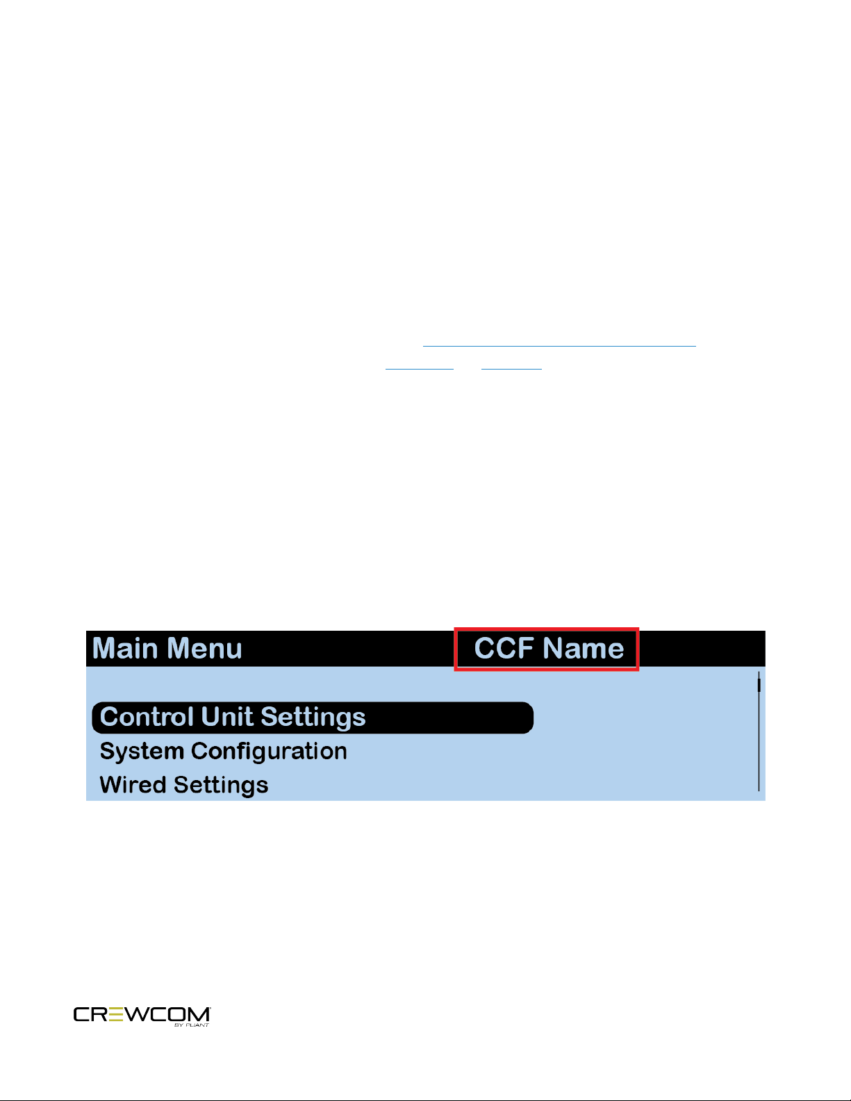
Determining Which CCFis Active
The CCF that is currently active for the CrewCom system is named in the Master CU's main menu.
Figure 1 CCF Name in CU Main Menu
Introduction - 12

The active CCFis also named in CrewWare above the System Diagram left-hand panel.
Figure 2 CCF Name in CrewWare
Conferences
A CrewCom Conference is an administrator-defined grouping of audio entities (inputs such as Radio Packs, wired
intercom ports, etc.). Conferences are then created dynamically by mixing one or more audio entities and routing
them to Conference subscribers accordingly. This method of subscription-based audio using Conferences is very
powerful. Point-to-point associations may also be easily constructed using this method. Each association requires a
separate, unique Conference. Conferences in CrewCom are full duplex (i.e. bidirectional) and there can be a
maximum of 64.
Default Conferences are included as part of a system’s "CrewCom Configuration File Defaults" on the previous page.
New Conferences can be created using CrewWare. (See the CrewWare Manual for more information.)
Profiles
Each CrewCom Radio Pack has a Profile that contains a variety of system settings that are defined as either global
profile settings or user settings. A Radio Pack Profile determines the functionality of an RP’s local controls, knobs, and
buttons (including Conference assignments), and allows customization for user preferences and roaming.
l
Global Profile Settings – These settings are part of the CrewCom Configuration File and are usually assigned
by a system administrator through customization in CrewWare during setup. A global profile setting is one that
assigns specific operational functions to a Pack’s volume knobs, talk buttons, and function buttons, along with
relay assignments and roaming options.
Introduction - 13

l
User Settings – A user setting is one that is classified as being adjustable by the Radio Pack user and is
limited to local device settings that do not alter the CrewCom Configuration File. The Profile can be used to
determine these settings, but they can also be customized directly from a Radio Pack (after a Profile is
loaded), via the Control Unit's menu, or via CrewWare.
Introduction - 14

Power Over CrewNet
What is Power-over-CrewNet?
Power-over-CrewNet (PoC) is a proprietary network protocol that carries operating voltage and current to CrewNetcompatible devices connected to the Control Unit via RJ-45 connections (Cat-5e or greater.) Control Units must
receive AC power via the supplied power cord in order to operate and provide necessary PoC to connected CrewNetcompatible devices. In addition, PoC can be supplied to devices downstream from a locally powered CrewCom Hub or
RT.
l
RJ-45 Copper Ports - Use the supplied 15 ft. (4.6 m) Cat 5e cable, or your own Cat 5e (or greater) cable (up to
330 ft. (100 m) in length). Any CrewCom device connected to CrewNet via a Cat 5e (or greater) cable will
receive Power Over CrewNet (PoC) from the Control Unit via the CrewNet port. In some situations, there may
be too many connected devices or the cable lengths may be too long for the PoC to adequately power all
devices, and this will be indicated with the NET PWR LED lighting red. In this case, one or more additional
Pliant 48VDC power supplies must be used (PPS-48V-02 included with Hub; sold separately with all other
devices).
l
Fiber (Optical) Ports - For a fiber CrewNet port, a Single Mode Fiber cable (duplex LC connector) will be
required (up to 32,800 ft. (10,000 m) in length). Any CrewCom device connected to CrewNet via fiber port must
receive power via a Pliant 48VDC power supply (PPS-48V-02 included with Hub; sold separately with all other
devices).
Powering Downstream Devices
In most cases, powering an RT and any daisy-chained RTs downstream via PoC is acceptable. However, depending
on cable lengths and number of RTs in your CrewCom configuration, you may need to utilize the 48VDC power supply
(PPS-48V, sold separately) to provide local power where needed. Under optimal conditions, seven connected RTs may
be powered from a locally powered RT; however, this number can vary greatly depending on the line lengths and the
number and configuration of those connected RTs.
To ensure best performance, especially with larger CrewCom configurations and longer cable lengths, Pliant
recommends utilizing the supplied 48VDC power supply to locally power each Hub. However, powering a Hub and the
devices connected to it via PoC may be advantageous in some smaller configurations.
Introduction - 15

Power for Fiber Devices
Fiber connections will not transfer power to a CrewCom device. For CrewNet-compatible devices using fiber
connectivity, local power must be supplied to that device using a Pliant 48VDC power supply (PPS-48V-02 included
with Hubs, sold separately for all other devices). Once local power is supplied to the device, downstream devices may
receive power via PoC (subject to limitations, depending on the line lengths and the number and configuration of
those connected devices.)
Introduction - 16

CHAPTER 3
PRODUCT OVERVIEW
This chapter consists of the following sections:
Hub 18
Copper Hub 19
Fiber Hub 21
Product Overview - 17

Hub
The CrewCom Hub operates on CrewNet and allows a variety of CrewCom devices to be interconnected. The Hub
consists of CrewNet ports that enable users to add more CrewCom devices, such as Radio Transceivers, in order to
extend the connection of their CrewCom system.
The Hub is a 1RU half-rack-mount capable device. A maximum of eight hubs (within up to four Hub layers) can be on
a CrewCom system. See "Hub Layers" on page27 for more information.
There are two types of CrewCom Hubs: the Copper Hub and the Fiber Hub. You may mix both types of hub in a single
CrewCom system.
Product Overview - 18

Copper Hub
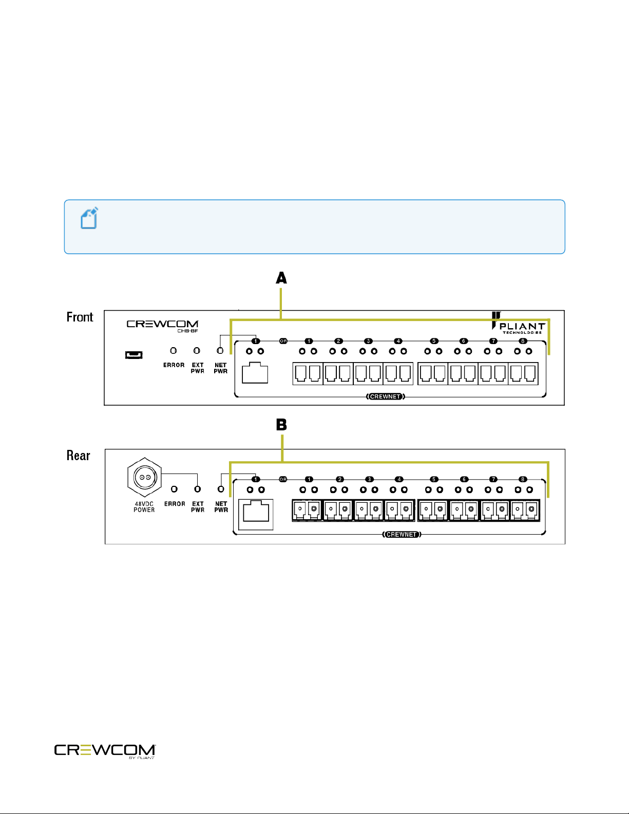
Note: The front and rear Copper Hub labels and LEDs are identical and display identical alerts. This
allows for both front and/or rear face mounting. See the figure below.
The Copper Hub (CHB-8C) has eight ports for copper connections and one fiber-optic port. Port 8 is an “either/or”
connection. The eighth copper port and the fiber port cannot operate simultaneously; the user must choose one or the
other. See "Power Over CrewNet" on page15 for more information about choosing between copper and fiber.
Figure 3 Copper Hub Front and Rear View
A.
USB Connection: Connects Hub to a computer to update firmware. See the CrewWare Manual for more
information on updating firmware.
B.
CREWNET Port Labels and Status LEDs for Ports 1–8: The front and rear Copper Hub labels and LEDs are
identical and display identical alerts. The port status LEDs indicate the CrewNet connection status. See "Hub
LEDs" on page32 for more LED information.
Product Overview - 19

C.
Copper Hub Power Tips: Port 1 cannot power devices. It can only accept power, and this
power is indicated with the NET PWR LED. Since Port 1 cannot source power to downstream
devices, even if the Hub is locally powered, any device connected to this port will require its
own local power supply. To ensure best performance, especially with larger CrewCom
configurations and longer cable lengths, Pliant recommends utilizing the supplied 48VDC
power supply to locally power each Hub. However, powering a Hub and the devices connected
to it via PoC may be advantageous in some smaller configurations.
48VDC Power Connection: Power connection for the Pliant 48VDC Power Supply (PPS-48V-02 included),
which allows the Hub to receive external (local) power.
To ensure best performance, especially with larger CrewCom configurations and longer cable lengths, Pliant
recommends utilizing the supplied 48VDC power supply to locally power each Hub. However, powering a Hub
and the devices connected to it via PoC may be advantageous in some smaller configurations.
D.
ERROR LED: Device error status indicator. This LED function is currently not available. See "Hub LEDs" on
page32 for more LED information.
E.
External (Local) Power (EXT PWR) LED: Indicates that external (local) power is being provided via a Pliant
48VDC Power Supply. See "Hub LEDs" on page32 for more LED information.
F.
Network Power (NET PWR) LED: Indicates the Hub is receiving PoC via Port 1. The LED indicates the presence
and strength of this PoC. See "Hub LEDs" on page32 for more LED information.
The Hub must be connected to Port 1 via a Cat 5e (or greater) copper cable in order for it to receive PoC. If PoC
is not used, the Hub must be powered externally by a Pliant 48VDC Power Supply.
G.
CREWNET Ports 1–8 and Status LEDs: The CrewNet ports allow the Hub to connect to the CrewCom Control
Unit, Radio Transceivers, and other Hubs, supporting a proprietary network design where all devices are part
of a CrewCom Configuration File that shares data, timing synchronization, and audio. Ports 1 through 7 are
copper (RJ-45, Cat 5e or greater); Port 8 can be either the last copper port or the separate duplex LC Single
Mode Fiber port, and only one may be used at a time. See "Hub LEDs" on page32 for more LED information.
Each port’s status LEDs indicate the status of the CrewNet connection. See "Hub LEDs" on page32 for more
LED information.
Product Overview - 20
Fiber Hub
Note: The front and rear Fiber Hub labels and LEDs are identical and display identical alerts. See the
figure below.
The Fiber Hub (CHB-8F) functions identically to the Copper Hub, except it has eight ports for fiber optic connections
and one copper port.
Port 1 is an “either/or” connection, and use of Port 1 is required for downstream operation of ports 2–8. The first fiber
port and the copper port cannot operate simultaneously; the user must choose one or the other. See "Power Over
CrewNet" on page15 for more information about choosing between copper and fiber.
Figure 4 Fiber Hub Front and Rear View
A.
CREWNET Port Labels and Status LEDs for Ports 1–8: The front and rear Fiber Hub labels and LEDs are
identical and display identical alerts. The port status LEDs indicate the CrewNet connection status. See "Hub
LEDs" on page32 for more LED information.
Product Overview - 21

B.
Note: Port 1 (copper only) is only capable of PoC input, and Port 1 cannot supply PoC output.
Either copper or fiber use of Port 1 is required for downstream operation of ports 2–8.
Fiber Hub Power Tips: Port 1 (copper only) cannot power devices. It can only accept power,
and this power is indicated with the NETPWR LED. Either copper or fiber use of Port 1 is
required for downstream operation of ports 2–8. Since Ports 1–8 cannot source power to
downstream devices, even if the Hub is locally powered, any device connected to a Fiber Hub
will require its own local power supply. To ensure best performance, especially with larger
CrewCom configurations and longer cable lengths, Pliant recommends utilizing the supplied
48VDC power supply to locally power each Hub.
CREWNET Ports 1–8 and Status LEDs: The CrewNet ports allow the Hub to connect to the CrewCom Control
Unit and Radio Transceivers, supporting a proprietary network design where all devices are part of a CrewCom
Configuration File that shares data, timing synchronization, and audio. Ports 2 through 8 are duplex LC Single
Mode Fiber ports; Port 1 can be either the first fiber port or the copper (RJ-45, Cat 5e or greater) port, and only
one may be used at a time. See "Hub LEDs" on page32 for more LED information.
Each port’s status LEDs indicate the status of the CrewNet connection. See "Hub LEDs" on page32 for more
LED information.
Product Overview - 22

CHAPTER 4
SETUP AND INSTALLATION
This chapter consists of the following sections:
Determine if you have a CCF. 24
Position Devices 25
How to Install Hubs 25
Connect to CrewNet 26
How to Connect CrewNet to Hubs 26
Hub Layers 27
Power On the System 28
How to Power On and Configure the System 28
Name a Device 29
Setup and Installation - 23

Determine if you have a CCF.
Your CU may have been pre-configured with a CrewCom Configuration File (CCF) at the factory or other source—
consult the documentation provided with your system for your specific configuration details, then proceed to "Position
Devices" on the next page. (If you have no configuration documentation or printed system diagram, contact the
person who provided your CrewCom system for assistance or contact Pliant Customer Support.)
If your CU has not been pre-configured with a CCF (and if you do not have a saved CCF on a USB drive to load to your
CU), you will need to install CrewCom’s software application, CrewWare, to create one. Then, you’ll load the CCF in
"Power On the System" on page28 of this guide. (For more information on building a system diagram and creating a
Configuration File, see the How to Create a System Diagram Video Tutorial.)
Setup and Installation - 24

Position Devices
After you plan your coverage area and determine if you have a CCF, you can begin positioning your Control Units
(CUs), Radio Transceivers (RTs), and Hub(s) .
How to Install Hubs
Determine a location for your Hub.
l If rack-mounting, secure the Hub using its rack-mounting hardware. Hubs can be mounted either single or two
side by side. (Mounting hardware, PAC-RMK-S and PAC-RMK-D, sold separately).
l Or place the device on a clean, flat surface. For your convenience, stick-on rubber feet are included with the
Hub.
Setup and Installation - 25

Connect to CrewNet
Important! Device port connections must match your CCF's system diagram in order to operate. Pliant
recommends making all cable connections from the CU to other CrewCom devices prior to powering
on the system. However, CrewCom devices(such as RTs) that are already present in the CCF may be
connected or replaced while the system is operating. When hot-swapping devices, Pliant
recommends waiting at least 10 seconds between disconnecting and reconnecting the device.
Connect your CrewCom system's devices via their available CrewNet RJ-45 Copper or duplex LC Fiber ports.
How to Connect CrewNet to Hubs
When your system includes a Copper or Fiber Hub, it should also be connected to CrewNet via its available CrewNet
ports.
CrewNet Connectivity
RJ-45 Copper Ports - Use the supplied 6.6 ft. (2 m) Cat 5e cable, or your own Cat 5e (or greater) cable (up to 330 ft.
(100 m) in length). Any CrewCom device connected to CrewNet via a Cat 5e (or greater) cable will receive Power Over
CrewNet (PoC) via the CrewNet port. (See "Power Over CrewNet" on page15 for more information.) In some
situations, there may be too many connected devices or the cable lengths may be too long for the PoC to adequately
power all devices, and this will be indicated with the NET PWR LED lighting red. To ensure best performance,
especially with larger CrewCom configurations and longer cable lengths, Pliant recommends utilizing the supplied
48VDC power supply (PPS-48V-02) to locally power each Hub. However, powering a Copper Hub and the devices
connected to it via PoC may be advantageous in some smaller configurations. See "Power Over CrewNet" on page15
for more information.
Fiber (Optical) Ports - For a fiber CrewNet port, a Single Mode Fiber cable (duplex LC connector) will be required (up
to 32,800 ft. (10,000 m) in length). Any CrewCom device connected to CrewNet via fiber port must receive power via a
Pliant 48VDC power supply (PPS-48V-02 included with Hub; sold separately with all other devices).
Setup and Installation - 26
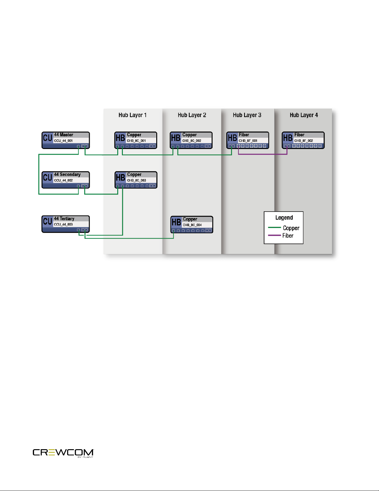
Hub Layers
Any additional Hub cascaded from a previous Hub is considered a new Hub layer. Cascading can be direct from a
previous Hub or through another CrewNet device. (See a diagram of some possible Hub configurations below.) A
helpful way of determining Hub layers is to count how many Hubs you pass through to reach the Master CU, including
the starting Hub.
Figure 5 Hub Layer Examples
Setup and Installation - 27

Power On the System
Note: In a multi-CUsystem, only the master CU requires a CCFto be loaded. (See
the Control Unit Manual for more information about CU priority.)
Once all desired CrewNet connections are made, power ON the CU to initiate system startup.
How to Power On and Configure the System
1. If using CrewCom Hubs, verify that they are utilizing the appropriatesupplied 48V local power supply.
2. Turn ON the power switch on the front of the CU.
3. Wait for the configuration file (CCF) to load on the system. The CU will display a progress bar during the load
process. A “CCF Loaded” message and a configuration file summary will display when the load is complete.
Once the message completes, the home screen will display on the front of the CU.
i. If your CU does not have a CCF, you need to load one. You can load a CCF via USB drive. See the
Control Unit and CrewWare Manuals for more information about this process.
4. Verify that your RTs and Hubs (if applicable) are receiving power by checking that their Power LEDs are green.
Under optimal conditions, seven additional connected RTs can be powered from one locally powered RT;
however, this number can vary greatly depending on the line lengths and the number and configuration of
those connected devices.
5. See the RPManual for instructions on setting up and using RadioPacks with your system.
Setup and Installation - 28

Name a Device
Note:This is a different procedure than editing the RP Profile's name. (See the CrewWare Manual
and/or the "How to Edit a Profile" video tutorial.)
CrewCom devices can be given a 16-character long name and an 8-character short name for display in the various
CrewWare menus and diagrams.
Hub name customization can only be performed from CrewWare. Please refer to the CrewWare Manual for
information about this process.
Setup and Installation - 29

CHAPTER 5
OPERATION
This chapter consists of the following sections:
Add More CrewCom Devices 31
Hub LEDs 32
Operation - 30

Add More CrewCom Devices
If you need to add additional CrewCom devices (e.g., a Hub, RT, or additional Control Units) after you’ve applied your
CrewCom Configuration File, you'll need to do the following:
1. Add the device(s) to your system diagram in CrewWare, then save the Configuration File change and apply the
new Configuration File to your system. (Remember, you cannot make System Diagram changes while
CrewWare is "live.") (See the CrewWare Manual for information on building a system diagram and uploading
the configuration file (CCF).)
2. Connect the additional CrewCom device(s) via an available CrewNet RJ-45 Copper or duplex LC Fiber port.
Operation - 31

Hub LEDs
Each LED on the Front and Rear of the Hub display identical connection and power status information, allowing the
user to monitor the device easily from both a free-standing or rack mount configuration.
Hub LED Descriptions
Connection/LED Description
ERROR LED
EXT PWRLED
NET PWRLED
CREWNET Status LEDs
This LED function is currently not available.
Green – External (local) power is present.
Off – No external (local) power is present.
Green – Power-over-CrewNet (PoC) is adequate for operation with current connections.
Off – No PoC is present.
Left Green – CrewNet connection is good.
Off – No CrewNet connection detected.
Right On (Green ) – 1000 Mbps link is detected.
Blinking (Green ) – Activity is detected.
Off – No CrewNet connection detected.
Operation - 32

CHAPTER 6
PRODUCT SPECIFICATIONS
This chapter consists of the following sections:
Hub Specifications 34
Product Specifications - 33

Hub Specifications
Hub Product Specifications
Specification* CHB-8C CHB-8F
CrewNet Ports (8
total connections)
Maximum CrewNet
Line Length
External Power In 48VDC Power Supply 48VDC Power Supply
Power-overCrewNet (PoC) In
Power-overCrewNet (PoC) Out
Dimensions (L × W
× H)
Weight 1.75 lbs (794 g) 1.75 lbs (794 g)
Operating
Environment
Maximum Altitude 6,562 ft. (2,000 m) 6,562 ft. (2,000 m)
RoHS Yes Yes
(7) RJ-45 for copper; (1) RJ-45 for copper
or duplex LC for Single Mode Fiber
Copper 330 ft. (100 m);
Fiber 32,800 ft. (10,000 m)
Port 1 (RJ-45) Port 1 (RJ-45)
Sourced by PoC: Ports 2–8;
Sourced by external power: Ports 2–8
8.62 in. × 1.73 in. × 8.68 in.
(21.9 cm × 4.4 cm × 22 cm)
-20° to 50° C (-4° to 122° F);
10% to 90% Humidity.
(7) duplex LC for Single Mode Fiber; (1) RJ-45 for
copper or duplex LC for Single Mode Fiber
Copper 330 ft. (100 m);
Fiber 32,800 ft. (10,000 m)
N/A
8.62 in. × 1.73 in. × 8.68 in.
(21.9 cm × 4.4 cm × 22 cm)
-20° to 50° C (-4° to 122° F);
10% to 90% Humidity.
*Notice About Specifications: While Pliant makes every attempt to maintain the accuracy of the information
contained in this manual, this information is subject to change without notice, and published device/system functions
and features are subject to firmware version. . Please check our website for the latest system specifications and
certifications.
Product Specifications - 34

CHAPTER 7
PRODUCT SUPPORT
This chapter consists of the following sections:
Product Support 36
Returning Equipment for Repair or Maintenance 36
Product Support - 35

Product Support
Pliant offers technical support via phone and email from 07:00 to 19:00 Central Time (UTC−06:00), seven days per
week.
1.844.475.4268 or +1.334.321.1160
technical.support@plianttechnologies.com
Visit www.plianttechnologies.com for product support, documentation, and live chat for help. (Live chat available
08:00 to 17:00 Central Time (UTC−06:00), Monday–Friday.)
Returning Equipment for Repair or Maintenance
All questions and/or requests for a Return Authorization Number should be directed to the Customer Service
department (customer.service@plianttechnologies.com). Do not return any equipment directly to the factory without
first obtaining a Return Material Authorization (RMA) Number. Obtaining a Return Material Authorization Number will
ensure that your equipment is handled promptly.
All shipments of Pliant products should be made via UPS, or the best available shipper, prepaid and insured. The
equipment should be shipped in the original packing carton; if that is not available, use any suitable container that is
rigid and of adequate size to surround the equipment with at least four inches of shock-absorbing material. All
shipments should be sent to the following address and must include a Return Material Authorization Number:
Pliant Technologies Customer Service Department
Attn: Return Material Authorization #
205 Technology Parkway
Auburn, AL 36830-0500
Product Support - 36

CHAPTER 8
SYSTEM MAINTENANCE AND STORAGE
This chapter consists of the following sections:
System Maintenance and Storage 38
Cleaning 38
Temperature and Humidity 38
System Maintenance and Storage - 37

System Maintenance and Storage
Cleaning
Generally, the CrewCom hardware should be cleaned only with a dry cloth. A soft cloth with rubbing alcohol may be
used to wipe the devices if needed, but you should avoid using rubbing alcohol on plastic components. Never spray
solvents or chemicals onto the devices.
All electronic devices can be susceptible to particulate contamination. If yours are exposed to an extremely dusty
environment, contact Pliant’s Customer Service for internal cleaning.
Temperature and Humidity
CrewCom components are designed to be very durable and can tolerate a wide range of environmental conditions;
however, you should take all necessary precautions to keep your system devices safe, dry, and out of extreme
conditions.
The Radio Transceiver is weather-resistant, including gaskets intended to prevent moisture entry from the top and
sides. The Cat 5e cable connection on the bottom is not water tight. If it is to be used in an outdoor environment,
protect the RT with a protective enclosure that will not interfere with the radio signals.
The Radio Packs are designed to work wherever people work. While the Radio Pack design is weather-resistant,
Radio Packs should not be submerged in liquids unnecessarily. Protect the battery compartment from water when
changing batteries. The battery compartment offers a route to the electronic circuitry.
System Maintenance and Storage - 38

CHAPTER 9
LICENSE AND COMPLIANCE INFORMATION
This chapter consists of the following sections:
License Information 40
License and Compliance Information - 39

License Information
Warning: Changes or modifications to this device not expressly approved by Pliant could void the
user’s authority to operate the equipment.
1. FCC Notices
A. This equipment has been tested and found to comply with the limits for a Class A digital device,
pursuant to part 15 of the FCC rules. These limits are designed to provide reasonable protection
against harmful interference when the equipment is operated in a commercial environment. This
equipment generates, uses, and can radiate radio frequency energy and, if not installed and used in
accordance with the instruction manual, may cause harmful interference to radio communications.
Operation of this equipment in a residential area is likely to cause harmful interference in which case
the user will be required to correct the interference at his own expense.
2. Canada, Industry Canada (IC) Notices
A. This Class A digital apparatus meets all requirements of the Canadian Interference Causing Equipment
Regulations.
Cet appareillage numérique de la classe A répond à toutes les exigencies de l’interférence canadienne
causant des règlements d’équipment.
3. South Korea Notices
A. The CrewCom Hub (CHB-8C, CHB-8F) complies with EMC requirement KN 32/35 and is labeled with
the KCmark and RRA (Radio Research Agency) registration number.
CrewCom Compliance Numbers
Model Numbers Compliance Model No.
CHB-8C, CHB-8C-02 HB2520
CHB-8F HB2521
License and Compliance Information - 40

CHAPTER 10
WARRANTY INFORMATION
This chapter consists of the following sections:
Warranty Information 42
Limited Warranty 42
Parts Limited Warranty 43
Warranty Information - 41

Warranty Information
Limited Warranty
CrewCom and MicroCom products are warranted to be free from defects in materials and workmanship for a period of
two years from the date of sale to the end user, under the following conditions:
l First year of warranty included with purchase.
l Second year of warranty for main models (CRP, CCU, CHB, CRT) requires product registration on the Pliant web
site. Register your product here: http://plianttechnologies.com/customer/account/login/
Tempest professional products carry a two-year product warranty.
All headsets and accessories (including Pliant-branded batteries) carry a one-year warranty.
The sole obligation of Pliant Technologies, LLC during the warranty period is to provide, without charge, parts and
labor necessary to remedy covered defects appearing in products returned prepaid to Pliant Technologies, LLC. This
warranty does not cover any defect, malfunction, or failure caused by circumstances beyond the control of Pliant
Technologies, LLC, including but not limited to negligent operation, abuse, accident, failure to follow instructions in
the Operating Manual, defective or improper associated equipment, attempts at modification and/or repair not
authorized by Pliant Technologies, LLC, and shipping damage. Products with their serial numbers removed or effaced
are not covered by this warranty.
This limited warranty is the sole and exclusive express warranty given with respect to Pliant Technologies, LLC
products. It is the responsibility of the user to determine before purchase that this product is suitable for the user’s
intended purpose. ANY AND ALL IMPLIED WARRANTIES, INCLUDING THE IMPLIED WARRANTY OF MERCHANTABILITY,
ARE LIMITED TO THE DURATION OF THIS EXPRESS LIMITED WARRANTY. NEITHER PLIANT TECHNOLOGIES, LLC NOR
ANY AUTHORIZED RESELLER WHO SELLS PLIANT PROFESSIONAL INTERCOM PRODUCTS IS LIABLE FOR INCIDENTAL OR
CONSEQUENTIAL DAMAGES OF ANY KIND.
Warranty Information - 42

Parts Limited Warranty
Replacement parts for Pliant Technologies, LLC products are warranted to be free from defects in materials and
workmanship for 120 days from the date of sale to the end user.
This warranty does not cover any defect, malfunction, or failure caused by circumstances beyond the control of Pliant
Technologies, LLC, including but not limited to negligent operation, abuse, accident, failure to follow instructions in
the Operating Manual, defective or improper associated equipment, attempts at modification and/or repair not
authorized by Pliant Technologies, LLC, and shipping damage. Any damage done to a replacement part during its
installation voids the warranty of the replacement part.
This limited warranty is the sole and exclusive express warranty given with respect to Pliant Technologies, LLC
products. It is the responsibility of the user to determine before purchase that this product is suitable for the user’s
intended purpose. ANY AND ALL IMPLIED WARRANTIES, INCLUDING THE IMPLIED WARRANTY OF MERCHANTABILITY,
ARE LIMITED TO THE DURATION OF THIS EXPRESS LIMITED WARRANTY. NEITHER PLIANT TECHNOLOGIES, LLC NOR
ANY AUTHORIZED RESELLER WHO SELLS PLIANT PROFESSIONAL INTERCOM PRODUCTS IS LIABLE FOR INCIDENTAL OR
CONSEQUENTIAL DAMAGES OF ANY KIND.
Warranty Information - 43
 Loading...