

CREVIS NA-9171, NA-9173, NA-9189 User Manual
1 FnIO MODBUS Adapter NA-9171, NA-9173 FnIO S-Series
Copyright(C) CREVIS Co.,Ltd Support +82-31-899-4599 URL : www.crevis.co.kr
Version 1.05
2013 CREVIS Co.,Ltd
NA-9171 / 9173
(RS-232) (RS-485)
User Manual
MODBUS Adapter

2 FnIO MODBUS Adapter NA-9171, NA-9173 FnIO S-Series
Copyright(C) CREVIS Co.,Ltd Support +82-31-899-4599 URL : www.crevis.co.kr
DOCUMENT CHANGE SUMMARY
REV
PAGE
REMARKS
DATE
EDITOR
1.0
New
Document
2011/10/07
JE Kang
1.01
13
IO LED Status Flashing Red ↔ Red
2011/10/21
JE Kang
1.02
6
Add your experience
2012/1/13
JE Kang
1.03
Modify the wrong letters
2012/2/13
JE Kang
1.04
Changed Crevis TEL
2013/4/4
JE KANG
1.05
Environment Spec. 50℃→55℃ (UL Temp)
2013/7/3
JE Kang

3 FnIO MODBUS Adapter NA-9171, NA-9173 FnIO S-Series
Copyright(C) CREVIS Co.,Ltd Support +82-31-899-4599 URL : www.crevis.co.kr
CONTENTS
1. Important Notes ......................................................................................................................................................... 6
1.1. Safety Instruction ...................................................................................................................................... 7
1.1.1. Symbols ......................................................................................................................................................... 7
1.1.2. Safety Notes ................................................................................................................................................ 7
1.1.3. Certification ................................................................................................................................................. 7
2. Specification ................................................................................................................................................................. 8
2.1. The Interface ............................................................................................................................................... 8
2.1.1. NA-9171(MODBUS RS-232) .............................................................................................................. 8
2.1.2. NA-9173 (MODBUS RS-485) ............................................................................................................. 9
2.2. Specification .............................................................................................................................................. 10
2.2.1. General Specification ............................................................................................................................. 10
2.2.2. Interface Specification........................................................................................................................... 11
2.3. LED Indicator ............................................................................................................................................. 12
2.3.1. Module Status LED (MOD) ................................................................................................................. 12
2.3.2. Received Data LED (RXD) .................................................................................................................... 12
2.3.3. Transmit Data LED(TXD)....................................................................................................................... 12
2.3.4. Expansion Module Status LED (I/O) ............................................................................................... 13
2.3.5. Field Power Status LED ........................................................................................................................ 13
3. Dimension .................................................................................................................................................................... 14
3.1. NA-9171 ...................................................................................................................................................... 14
3.2. NA-9173 ...................................................................................................................................................... 14
4. Mechanical Set Up ................................................................................................................................................... 15
4.1. Total Expansion ........................................................................................................................................ 15

4 FnIO MODBUS Adapter NA-9171, NA-9173 FnIO S-Series
Copyright(C) CREVIS Co.,Ltd Support +82-31-899-4599 URL : www.crevis.co.kr
4.2. Plugging and Removal of the Components. .............................................................................. 15
4.3. Internal FnBus/Field Power Contacts ............................................................................................. 16
5. MODBUS Electrical Interface ............................................................................................................................... 17
5.1. FnBus System ............................................................................................................................................ 17
FnBus Pin Description ............................................................................................................................................ 18
5.2. MODBUS Electrical Interface .............................................................................................................. 19
5.2.1. NA-9171 (RS-232) ................................................................................................................................... 19
5.2.2. NA-9173 (RS-485) ................................................................................................................................... 19
5.2.3. Terminator Resistor ................................................................................................................................ 20
5.2.4. MODBUS DIP Switch Setup ................................................................................................................ 21
5.2.5. MODBUS Address Setup ..................................................................................................................... 22
5.2.6. I/O Process Image Map ....................................................................................................................... 23
5.2.7. MODBUS Interface Register / Bit Map .......................................................................................... 23
5.3. Example ....................................................................................................................................................... 24
5.3.1. Example of Input Process Image(Input Register) Map .......................................................... 24
5.3.2. Example of Output Process Image(Output Register) Map .................................................. 27
6. MODBUS INTERFACE .............................................................................................................................................. 29
6.1. MODBUS Transmission Mode ........................................................................................................... 29
6.1.1. RTU Transmission Mode ...................................................................................................................... 29
6.1.2. ASCII Transmission Mode ................................................................................................................... 29
6.2. Supported MODBUS Function Codes ............................................................................................ 29
6.2.1. 1 (0x01) Read Coils ................................................................................................................................ 30
6.2.2. 2 (0x02) Read Discrete Inputs ........................................................................................................... 31

5 FnIO MODBUS Adapter NA-9171, NA-9173 FnIO S-Series
Copyright(C) CREVIS Co.,Ltd Support +82-31-899-4599 URL : www.crevis.co.kr
6.2.3. 3 (0x03) Read Holding Registers ..................................................................................................... 32
6.2.4. 4 (0x04) Read Input Registers ........................................................................................................... 33
6.2.5. 5 (0x05) Write Single Coil ................................................................................................................... 34
6.2.6. 6 (0x06) Write Single Register .......................................................................................................... 35
6.2.7. 8 (0x08) Diagnostics .............................................................................................................................. 36
6.2.8. 15 (0x0F) Write Multiple Coils ........................................................................................................... 38
6.2.9. 16 (0x10) Write Multiple Registers ................................................................................................. 39
6.2.10. 23 (0x17) Read/Write Multiple Registers ..................................................................................... 40
6.2.11. Error Response ......................................................................................................................................... 41
6.3. MODBUS Special Register Map........................................................................................................ 42
6.3.1. Adapter Identification Special Register (0x1000, 4096) ......................................................... 42
6.3.2. Adapter Watchdog Time, other Time Special Register (0x1020, 4128) ......................... 43
6.3.3. Adapter Information Special Register (0x1100, 4352) ............................................................ 44
6.3.4. Expansion Slot Information Special Register (0x2000, 8192) .............................................. 45
6.4. MODBUS Reference ............................................................................................................................... 47
7. Trouble Shooting...................................................................................................................................................... 48
7.1. How to diagnose by LED indicator ................................................................................................. 48
APPENDIX A ......................................................................................................................................................................... 50
A.1. Product List............................................................................................................................................................. 50
A.2. Glossary .................................................................................................................................................................... 52

6 FnIO MODBUS Adapter NA-9171, NA-9173 FnIO S-Series
Copyright(C) CREVIS Co.,Ltd Support +82-31-899-4599 URL : www.crevis.co.kr
1. Important Notes
Solid state equipment has operational characteristics differing from those of electromechanical equipment.
Safety Guidelines for the Application, Installation and Maintenance of Solid State Controls describes some important
differences between solid state equipment and hard-wired electromechanical devices.
Because of this difference, and also because of the wide variety of uses for solid state equipment, all persons
responsible for applying this equipment must satisfy themselves that each intended application of this equipment is
acceptable.
In no event will CREVIS be responsible or liable for indirect or consequential damages resulting from the use or
application of this equipment.
The examples and diagrams in this manual are included solely for illustrative purposes. Because of the many variables
and requirements associated with any particular installation, CREVIS cannot assume responsibility or liability for actual
use based on the examples and diagrams.
If you don’t follow the directions, it could cause a personal injury, damage to the equipment or explosion
Do not assemble the products and wire with power applied to the system. Else it may cause an electric arc, which
can result into unexpected and potentially dangerous action by field devices. Arching is explosion risk in
hazardous locations. Be sure that the area is non-hazardous or remove system power appropriately before
assembling or wiring the modules.
Do not touch any terminal blocks or IO modules when system is running. Else it may cause the unit to an electric
shock or malfunction.
Keep away from the strange metallic materials not related to the unit and wiring works should be controlled by the
electric expert engineer. Else it may cause the unit to a fire, electric shock or malfunction.
If you disobey the instructions, there may be possibility of personal injury, damage to equipment or
explosion. Please follow below Instructions.
Check the rated voltage and terminal array before wiring. Avoid the circumstances over 55℃ of temperature.
Avoid placing it directly in the sunlight.
Avoid the place under circumstances over 85% of humidity.
Do not place Modules near by the inflammable material. Else it may cause a fire.
Do not permit any vibration approaching it directly.
Go through module specification carefully, ensure inputs, output connections are made with the specifications. Use
standard cables for wiring.
Use Product under pollution degree 2 environment.
Warning!
Caution!
7 FnIO MODBUS Adapter NA-9171, NA-9173 FnIO S-Series
Copyright(C) CREVIS Co.,Ltd Support +82-31-899-4599 URL : www.crevis.co.kr
1.1. Safety Instruction
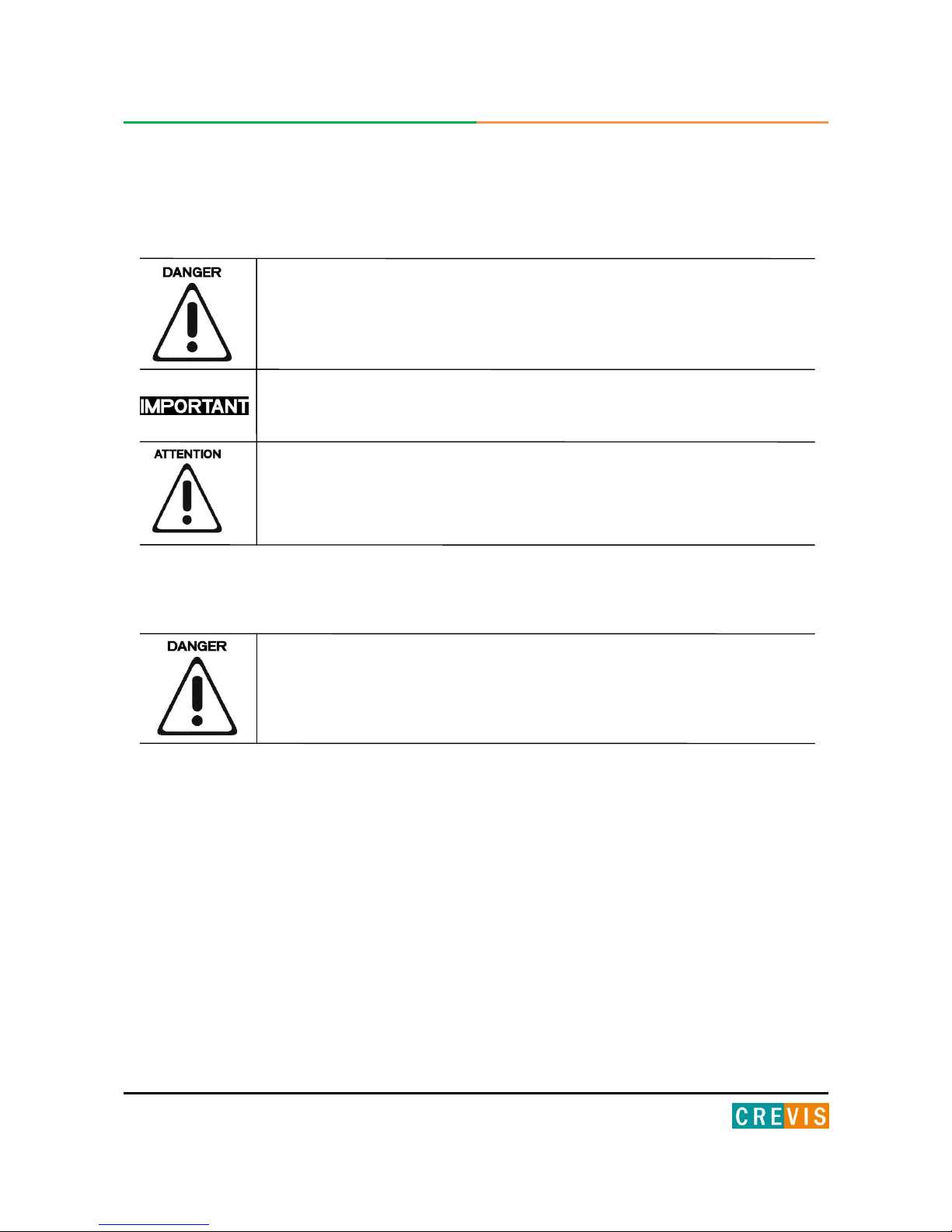
1.1.1. Symbols
Identifies information about practices or circumstances that can cause an explosion in a
hazardous environment, which may lead to personal injury or death property damage or
economic loss.
Identifies information that is critical for successful application and understanding of the
product.
Identifies information about practices or circumstances that can lead to personal
injury, property damage, or economic loss.
Attentions help you to identity a hazard, avoid a hazard, and recognize the consequences.
1.1.2. Safety Notes
The modules are equipped with electronic components that may be destroyed by electrostatic
discharge. When handling the modules, ensure that the environment (persons, workplace and
packing) is well grounded. Avoid touching conductive components, e.g. FnBUS Pin.
1.1.3. Certification
c-UL-us UL Listed Industrial Control Equipment, certified for U.S. and Canada
See UL File E235505
DNV CERTIFICATE No. A-10666 (NA-9173)
LR/FCC
CE Certificate
EN 61000-6-2; Industrial Immunity
EN 61000-6-4; Industrial Emissions
8 FnIO MODBUS Adapter NA-9171, NA-9173 FnIO S-Series
Copyright(C) CREVIS Co.,Ltd Support +82-31-899-4599 URL : www.crevis.co.kr
2. Specification
2.1. The Interface
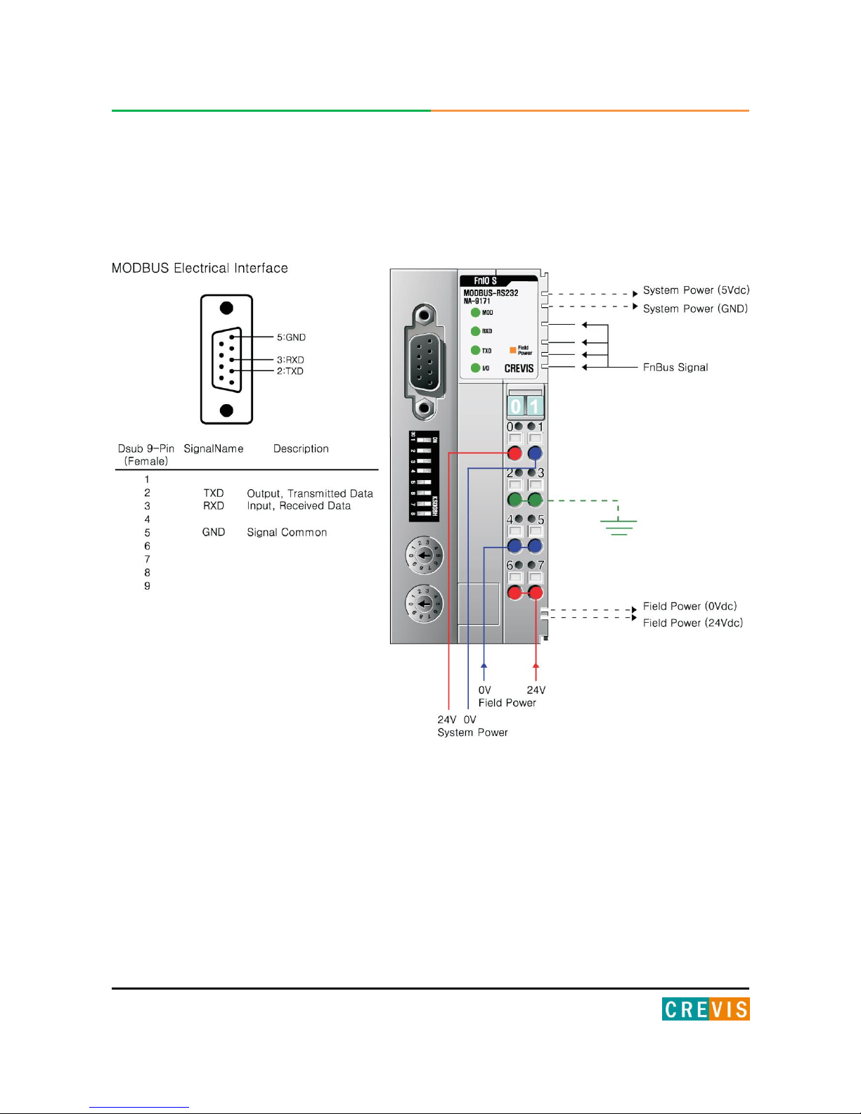
2.1.1. NA-9171(MODBUS RS-232)
9 FnIO MODBUS Adapter NA-9171, NA-9173 FnIO S-Series
Copyright(C) CREVIS Co.,Ltd Support +82-31-899-4599 URL : www.crevis.co.kr
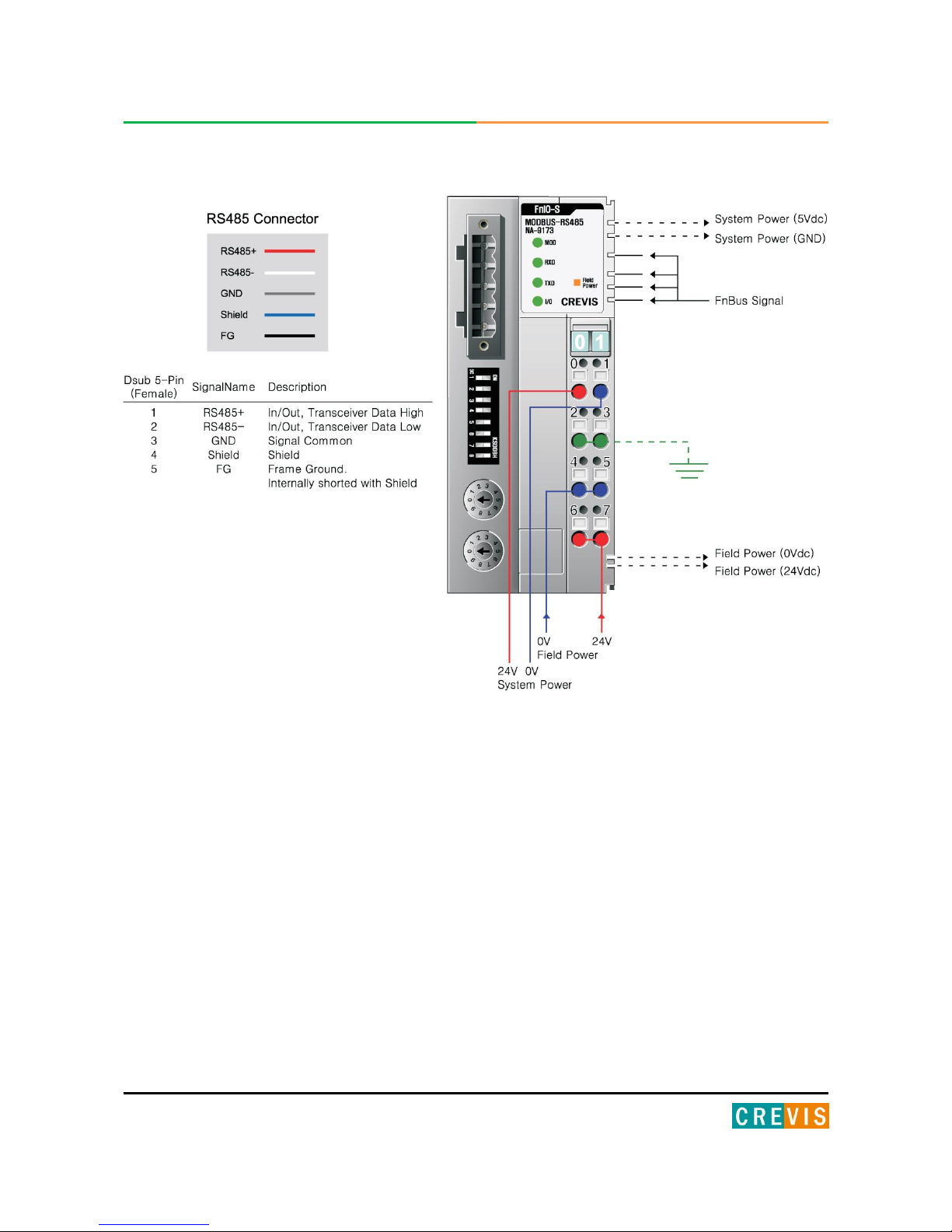
2.1.2. NA-9173 (MODBUS RS-485)
10 FnIO MODBUS Adapter NA-9171, NA-9173 FnIO S-Series
Copyright(C) CREVIS Co.,Ltd Support +82-31-899-4599 URL : www.crevis.co.kr
2.2. Specification
2.2.1. General Specification
General Specification
System Power
Supply voltage : 24Vdc nominal
Supply voltage range : 11~28.8Vdc
Protection : Output current limit (Min. 1.5A)
Reverse polarity protection
Power Dissipation
70mA typical @24Vdc
Current for I/O Module
1.5A @5Vdc
Isolation
System power to internal logic : Non-isolation
System power to I/O driver : Isolation
Field Power
Supply voltage : 24Vdc nominal
Supply voltage range : 11~28.8Vdc
Max. Current Field Power
Contact
DC 10A Max.
Weight
150g
Module Size
45mm x 99mm x 70mm
Environment Condition
Refer to Environment Specification
Environmental Specifications
Operating Temperature
-20 to 55℃
Non-Operating Temperature
-40℃ to 85℃
Relative Humidity
5%~90% non-condensing
Operating Altitude
2000m
Mounting
DIN rail
11 FnIO MODBUS Adapter NA-9171, NA-9173 FnIO S-Series
Copyright(C) CREVIS Co.,Ltd Support +82-31-899-4599 URL : www.crevis.co.kr
2.2.2. Interface Specification
Interface Specification, NA-9171(RS-232), NA-9173(RS-485)
Adapter Type
Slave node (MODBUS Serial RTU/ASCII Server)
Max. Expansion Module
32 slots
Max. Input Size
126words (252bytes)
Max. Output Size
126words (252bytes)
Max. Length Bus Line
1200m (NA-9173, RS-485, depend on baud rate),
15m (NA-9171, RS-232)
Max. Nodes
64 nodes (NA-9173, RS-485),
1 node (NA-9171, RS-232)
Baud rate
1200, 2400, 4800, 9600, 19200, 38400, 57600, 115200bps
Protocol
RTU and ASCII
Interface Connector
5 Pin Open Connector (NA-9173, RS-485)
Dsub 9pin (Female) (NA-9171, RS-232)
Settable Node Address
1~99 with two rotary switches
Indicator
5 LEDs
1 Green/Red, Module Status (MOD)
1 Green, Received Data (RXD)
1 Green, Transmit Data (TXD)
1 Green/Red Expansion Module Status (I/O)
1 Green, Field Power Status
Module Location
Starter module – left side of FnIO system
Field Power Detection
About 11Vdc
12 FnIO MODBUS Adapter NA-9171, NA-9173 FnIO S-Series
Copyright(C) CREVIS Co.,Ltd Support +82-31-899-4599 URL : www.crevis.co.kr
2.3. LED Indicator
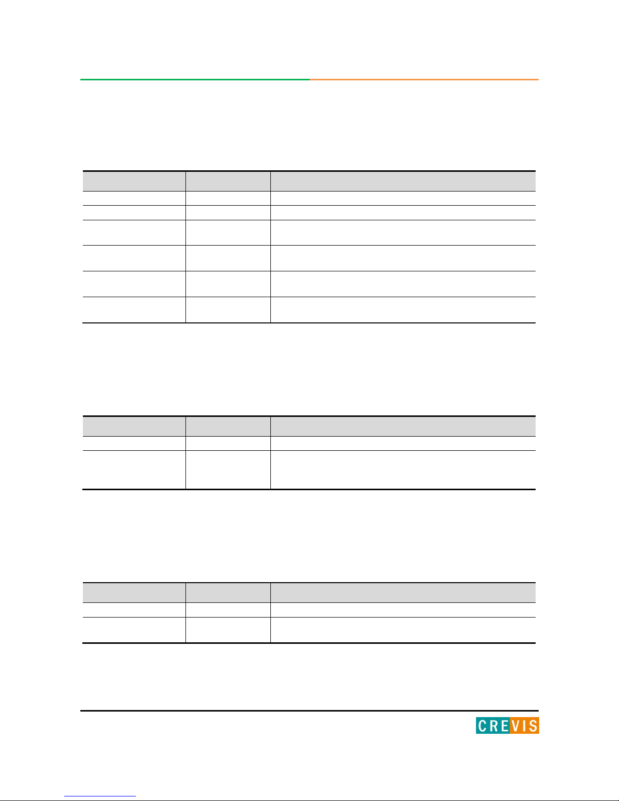
2.3.1. Module Status LED (MOD)
State
LED is :
To indicate :
No Power
Off
No power is supplied to the unit.
Device Operational
Green
The unit is operating in normal condition.
Device in Standby
Flashing Green
The device needs commissioning due to configuration missing,
incomplete or incorrect.
MODBUS Error
Green/Red Toggle
MODBUS error such as watchdog error, CRC/LRC error, Setup
dip switch, error, etc.
Minor Fault
Flashing Red
Recoverable Fault
- EEPROM sum check error.
Unrecoverable Fault
Red
The device has an unrecoverable fault.
- Memory error or CPU watchdog error.
2.3.2. Received Data LED (RXD)
State
LED is :
To indicate :
Not Powered
Off
Device is not on-line or may not be powered
Adapter received
correct message frame
Flashing Green
Adapter (Slave) received correct frame which address to the slave
or broadcast.
About 20msec flashing.
2.3.3. Transmit Data LED(TXD)
State
LED is :
To indicate :
Not Powered
Off
Device is not on-line or may not be powered
Adapter transmit frame
Flashing Green
Adapter (Slave) transmit frame.
About 20msec flashing.
13 FnIO MODBUS Adapter NA-9171, NA-9173 FnIO S-Series
Copyright(C) CREVIS Co.,Ltd Support +82-31-899-4599 URL : www.crevis.co.kr
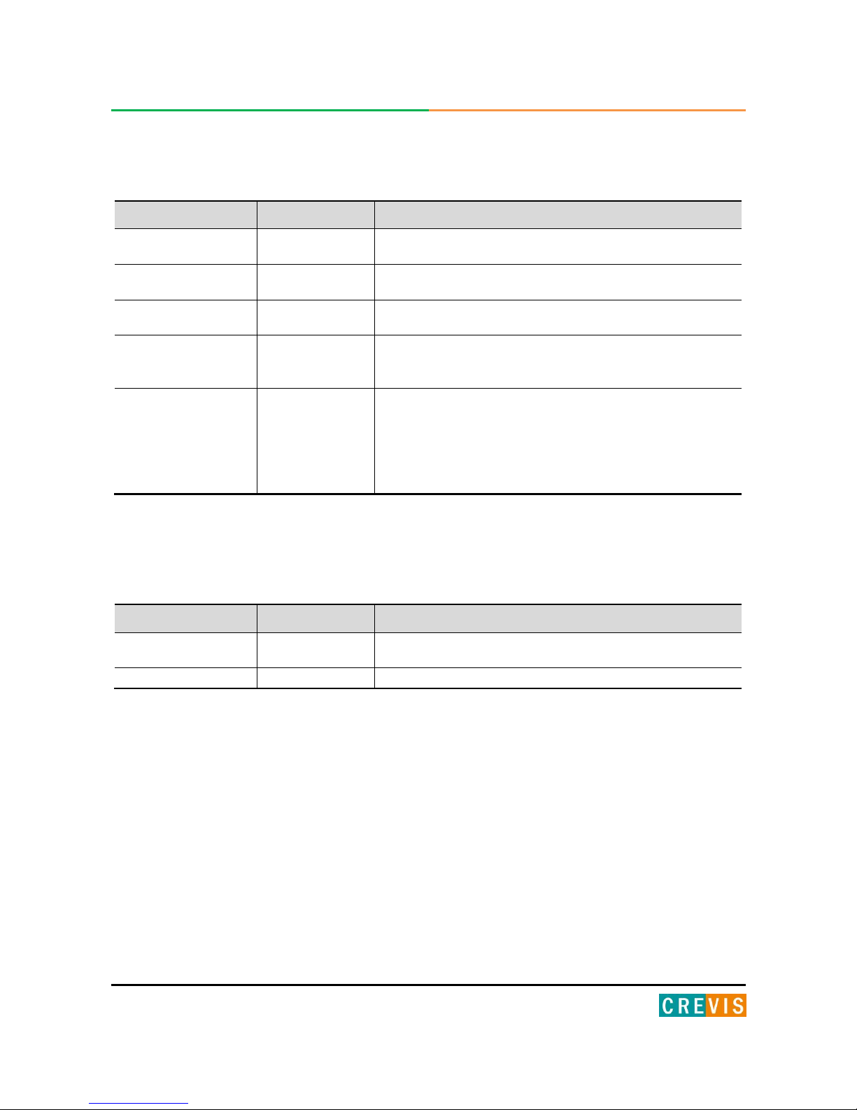
2.3.4. Expansion Module Status LED (I/O)
2.3.5. Field Power Status LED
State
LED is :
To indicate :
Not Powered
No Expansion Module
Off
Device has no expansion module or may not be powered
FnBus On-line,
Do not Exchanging I/O
Flashing Green
FnBus is normal but does not exchanging I/O data
(Passed the expansion module configuration).
FnBus Connection,
Run Exchanging IO
Green
Exchanging I/O data
FnBus connection fault
during exchanging IO
Red
One or more expansion module occurred in fault state.
- Changed expansion module configuration.
- FnBus communication failure.
Expansion
Configuration Failed
Flashing Red
Failed to initialize expansion module
- Detected invalid expansion module ID.
- Overflowed Input / Output Size
- Too many expansion module
- Initial protocol failure
- Mismatch vendor code between adapter and expansion module.
State
LED is :
To indicate :
Not Supplied Field
Power
Off
Not supplied 24V dc field power
Supplied Field Power
Green
Supplied 24V dc field power
14 FnIO MODBUS Adapter NA-9171, NA-9173 FnIO S-Series
Copyright(C) CREVIS Co.,Ltd Support +82-31-899-4599 URL : www.crevis.co.kr
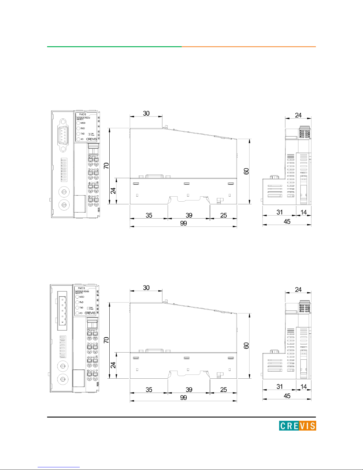
3. Dimension
3.1. NA-9171
(mm)
3.2. NA-9173
(mm)
15 FnIO MODBUS Adapter NA-9171, NA-9173 FnIO S-Series
Copyright(C) CREVIS Co.,Ltd Support +82-31-899-4599 URL : www.crevis.co.kr
4. Mechanical Set Up
4.1. Total Expansion
The number of the module assembly that can be connected is 32. So the maximum length is 426mm Exception.
ST-2748 is excepted to calculate maximum length because that is double width module.
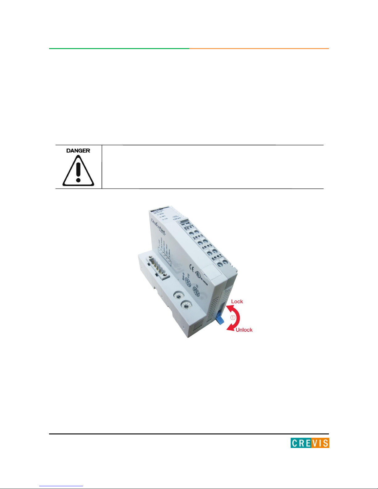
4.2. Plugging and Removal of the Components.
Before work is done on the components, the voltage supply must be turned
off.
As above figure in order to safeguard the FnIO module from jamming, it should be fixed onto the DIN rail with locking
level. To do so, fold on the upper of the locking lever.
To pull out the FnIO module, unfold the locking lever as below figure.
16 FnIO MODBUS Adapter NA-9171, NA-9173 FnIO S-Series
Copyright(C) CREVIS Co.,Ltd Support +82-31-899-4599 URL : www.crevis.co.kr
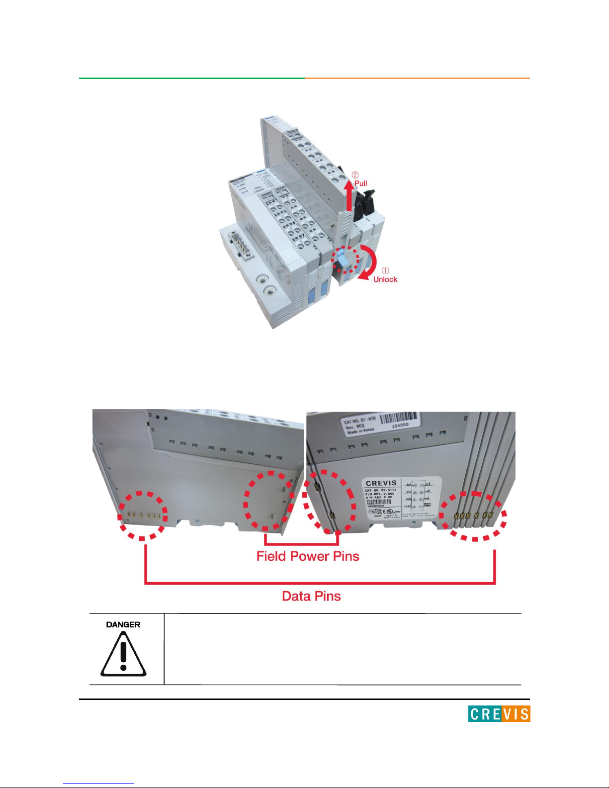
4.3. Internal FnBus/Field Power Contacts
Communication between the NA series and the expansion module as well as system / field power supply of the bus
modules is carried out via the internal bus. It is comprised of 6 data pin and 2 field power pin.
Do not touch data and field power pins in order to avoid soiling and damage by ESD noise.
 Loading...