

Page 1

NOTEBOOK COMPUTER
RT886EX
USER’S GUIDE
Page 2

Copyright © 2008 CReTE Systems Inc. All rights reserved.
No part of this publication may be processed; such as reproduced,
transmitted, transcribed, stored in a retrieval system, translated into
any computer language in any form, or by any means of electronic,
mechanical, magnetic, optical, chemical, or others without the prior
written permission of the manufacturer.
The manufacturer reserves the right to revise this publication and to
make changes to the contents here of without obligation to notify any
person of such revision or changes.
The manufacturer makes no representations or warranties, either
expressed or implied, about the contents and specifically disclaims
any warranties as to merchantability or fitness for any particular
purpose. Any of the software described in this manual is sold or
licensed "as is". Should the programs prove defective following
purchase, the buyer (and not the manufacturer, its distributor, or its
dealer) assumes the entire cost of all necessary servicing, repair and
any incidental or consequential damages resulting from any software
defects.
Trademark Acknowledgments
Windows is registered trademarks of Microsoft Corp.
Intel® Core™2 Duo processor is the registered trademark of Intel
Corp.
All product and company names are trademarks or registered
trademarks of their respective holders.
Page 3

EMC and Safety Notice
Federal Communications Commission Statement
This equipment has been tested and found to comply with the limits
for a class B digital device, under part 15 of the FCC Rules. These
limits are designed to provide reasonable protection against harmful
interference in a residential installation.
This equipment generates, uses, and radiates radio frequency energy,
and if not installed and used in accordance with the instructions, may
cause harmful interference to radio communications. However, there
is no guarantee that interference will not occur in a particular
installation. If this equipment does cause harmful interference to
radio or television reception, which can be determined by turning the
equipment off and on, the user is encouraged to try to correct the
interference by one or more of the following measures:
- Re-orient or relocate the receiving antenna.
- Increase the separation between the equipment and receiver.
- Connect the equipment into an outlet on a circuit different from
that to which the receiver is connected.
- Consult the dealer or an experienced radio/TV technician for help.
Regulatory Information/Disclaimers
Installation and use of this computer must be in strict accordance
with the instructions included in the user documentation provided
with the product. Any changes or modifications (including the
antennas) made to this device that are not expressly approved by the
manufacturer may void the user’s authority to operate the equipment.
The manufacturer is not responsible for any radio or television
interference caused by unauthorized modification of this device, or
the substitution of the connecting cables and equipment other than
manufacturer specified. It is the responsibility of the user to correct
any interference caused by such unauthorized modification,
substitution or attachment. Manufacturer and its authorized resellers
or distributors will assume no liability for any damage or violation of
Page 4

government regulations arising from failing to comply with these
guidelines.
Important Note
FCC RF Radiation Exposure Statement:
This equipment complies with FCC RF radiation exposure limits set
forth for an uncontrolled environment. This device and its antenna
must not be co-located or operated with any other antenna or
transmitter.
CE
Products with the CE Marking comply with both the EMC Directive
(89/336/EEC) and the Low Voltage Directive (73/23/EEC) issued by
the Commission of the European Community.
Compliance with these directives implies conformity to the following
European Norms:
EN55022 (CISPR 22) Radio Frequency Interference
EN55024 (EN61000-4-2, EN61000-4-3, EN61000-4-4,
EN61000-4-5, EN61000-4-6, EN61000-4-8,
EN61000-4-11, EN61000-3-2, EN61000-3-3) Generic
Immunity Standard
EN60950 (IEC950) Product Safety
R&TTE (CE) Manual Regulatory Requirement
(WLAN - IEEE 802.11 a.b.g)
802.11 a.b.g Restrictions:
European standards dictate maximum radiated transmit power of
100mW EIRP and frequency range 2.400-2.4835 GHz. In France, the
equipment must be restricted to the 2.4465-2.4835 GHz frequency
range and must be restricted to indoor use.
Page 5

CE Declaration of Conformity
Is herewith confirmed to comply with the requirements set out in the
Council Directive on the approximation of the laws of the member
states relating to Electromagnetic Compatibility (89/336/EEC), Lowvoltage Directive (73/23/EEC) and the Amendment Directive
(93/68/EEC), the procedures given in European Council Directive
99/5/EC and 89/3360EEC.
The equipment was passed. The test was performed according to the
following European standards.
EN 300 328 V.1.4.1 (2003-04)
EN 301 489-1 V.1.4.1 (2002-04)/EN 301 489-17 V.1.2.1 (2002-04)
EN 50371:2002
EN 60950:2000
UL, TÜV
AC Adapter (TÜV includes EN60950 LVD)
Page 6

Power Conservation
This computer consumes much less power than conventional
computers. However, power consumption may be reduced by
properly configuring the Power Management Setup.
It is recommended the power saving functions be enabled even when
not running on battery power.
Power Management does not degrade performance while saving
power.
Environmental Information, Material Safety
and Recycling
Caution: Risk of explosion if battery is replaced by an incorrect
type. Dispose of used batteries according to the
instructions.
All materials used in the construction of this equipment are
recyclable or environmentally friendly.
Please recycle the packing materials, and at the end of the product's
life, all other materials by local regulations.
Please refer “Material and Recycling” for the contents of the
materials.
- The equipment may still contain tiny amount of hazardous
substances for health and environment, though those are below
control level.
- To avoid spreading such substances into the eco system, and to
minimize the pressure on the natural, you are encouraged to use
the appropriate take-back. Those will reuse or recycle most of
the materials in a sound way after end life.
- The crossed bin symbol indicates proper disposal is required.
- For more information on collection, reuse and recycling, please
consult local or regional waste administration.
Page 7

- You can also contact the dealer for more information on the
environmental details of the equipment.
Page 8

CONTENTS
GETTING STARTED ...........................................................................................1
UNPACKING .......................................................................................................... 1
QUICK OPERATION................................................................................................ 2
CONTROLS AND INDICATORS.................................................................................3
USEFUL INFORMATION ...................................................................................7
LOCATION ............................................................................................................. 7
RUGGEDNESS ........................................................................................................7
OPERATING SYSTEMS............................................................................................ 8
AC ADAPTER ........................................................................................................8
BATTERY...............................................................................................................9
BOOT UP AND POST...........................................................................................11
STANDBY/HIBERNATE/RESUME ..........................................................................11
SHUTDOWN .........................................................................................................12
RTC.................................................................................................................... 12
REPLACING MODULES.........................................................................................12
COMPONENTS AND FUNCTIONS.................................................................14
KEYBOARD ......................................................................................................... 14
PRINTER CABLE ..................................................................................................15
HARD DISK DRIVE ..............................................................................................15
DVD-ROM DRIVE..............................................................................................16
EXPRESS AND PCMCIA CARDS ..........................................................................16
DOCKUNDER (OPTIONAL) ...................................................................................17
OPTIONAL DEVICES........................................................................................22
MEMORY CARD...................................................................................................22
2
ND
BATTERY.......................................................................................................22
LAN AND FAX/MODEM CARD ............................................................................22
WIRELESS LAN CARD ........................................................................................22
DVD-RW DRIVE ................................................................................................22
2
ND
HDD .............................................................................................................22
TOUCH SCREEN...................................................................................................22
PCMCIA COVER ................................................................................................23
VEHICLE ADAPTER..............................................................................................23
DUAL BATTERY CHARGER..................................................................................23
Page 9

D
OCKUNDER.......................................................................................................23
SPECIFICATIONS ..............................................................................................24
CPU....................................................................................................................24
MEMORY............................................................................................................. 24
DISPLAY.............................................................................................................. 24
KEYBOARD ......................................................................................................... 25
HARD DISK DRIVE ..............................................................................................25
TOUCH SCREEN...................................................................................................25
I/O PORTS............................................................................................................ 25
AC ADAPTER ......................................................................................................26
VEHICLE ADAPTER..............................................................................................26
BATTERY.............................................................................................................26
SYSTEM UNIT DIMENSIONS AND WEIGHT ...........................................................27
MATERIALS AND RECYCLING.............................................................................. 27
ENVIRONMENTAL................................................................................................ 28
BIOS SETUP ........................................................................................................29
MAIN MENU........................................................................................................ 29
IDE CHANNEL 0 MASTER SUB-MENU................................................................. 31
IDE CHANNEL 0 SLAVE SUB-MENU....................................................................32
IDE CHANNEL 1 MASTER SUB-MENU................................................................. 33
IDE CHANNEL 1 SLAVE SUB-MENU....................................................................34
GENERAL HELP WINDOW....................................................................................35
ADVANCED MENU .............................................................................................. 36
ADVANCED MENU SELECTIONS ..........................................................................36
SIO SMC227 CONFIGURATION SUB-MENU........................................................39
SECURITY MENU.................................................................................................42
RF SECURITY CONTROL SUB-MENU ...................................................................44
TPM STATE MENU..............................................................................................45
BOOT MENU........................................................................................................ 46
EXIT MENU .........................................................................................................47
UTILITIES AND DRIVERS...............................................................................48
CHIPSET ..............................................................................................................48
VGA UTILITY .....................................................................................................48
DISPLAY CAPABILITY..........................................................................................48
AUDIO DRIVER.................................................................................................... 49
USB 2.0 ..............................................................................................................49
TOUCH SCREEN DRIVER...................................................................................... 49
DVD-ROM DRIVER ........................................................................................... 50
PCMCIA DRIVER ...............................................................................................50
Page 10

M
INI PCI 1G AX92200 LAN..............................................................................50
MINI PCI INT8100 LAN ....................................................................................50
MINI PCI-E 1G RTL8111B LAN .......................................................................50
MINI PCI-E INTEL 3945ABG WLAN.................................................................50
FAX/MODEM CARD DRIVER................................................................................ 51
BLUETOOTH DRIVER ........................................................................................... 51
GPRS/GSM (SIEMENS MC75) DRIVER ..............................................................51
WIRELESS MANAGER..........................................................................................51
MAINTENANCE/SERVICE ..............................................................................52
CLEANING ........................................................................................................... 52
TROUBLESHOOTING ............................................................................................52
RMA SERVICE ....................................................................................................52
Page 11
Getting Started
1
GETTING STARTED
Unpacking
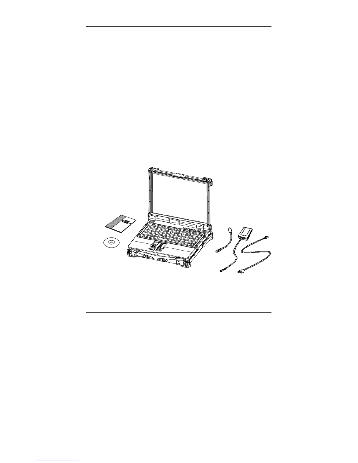
The following components come with your computer. If anything is
missing or damaged, please notify the dealer immediately.
- Computer unit
- Removable drive installed on computer
- AC Adapter
- AC Power Cord
- Utility CD
- User's Guide
- External Keyboard Adapter Cable
- Printer adapter cable
- Carrying Bag
Page 12

Getting Started
2
Quick Operation
- Loosen the battery screw, remove the battery insulation sheet,
and mount the battery.
- Attach the AC adapter and charge battery for at least 10 minutes.
Turn ON the computer by pressing the power switch momentarily.
Notice:
- When ambient temperature is under 0℃, the system may not
boot up immediately. System will beep with heater light flashing
while heater working. After 10~15 minutes, the system will boot
up automatically.
- Under emergency situation, to skip heating and boot up system
immediately by pressing power button for >10 seconds. (But can
not guarantee all devices on the computer work properly)
- Turn OFF the computer using either one of the following
procedures:
1. Press power switch to “Shut Down”, “Standby”* or
“Hibernate”* dependent on operating system (OS) and power
management settings.
2. Press power switch for 4 seconds for a “Hard” power off.
System shuts down immediately without saving any data or
parameters.
*: Some operating systems may not support these
functions.
3. Click Start → Shut Down in Windows to Turn OFF.
Driver or application software installation may be necessary for
further operation.
Page 13
Getting Started
3
Controls and Indicators
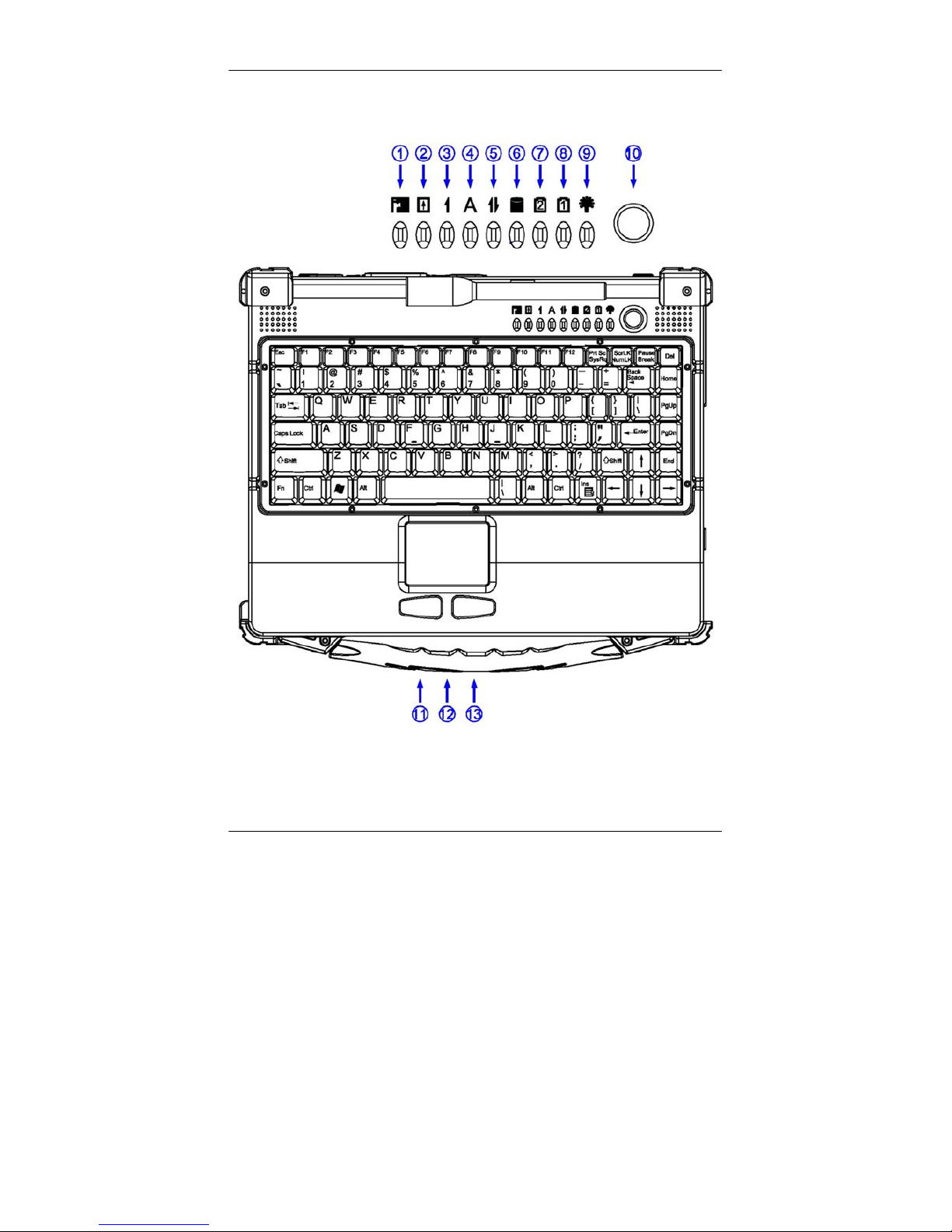
Controls and Indicators (Upper)
1. Heater
2. BT/WLAN/GPS
3. Keyboard Number Lock
Page 14
Getting Started
4
4. Keyboard Caps Lock
5. Keyboard Scroll Lock
6. HDD in use
7. Secondary Battery Charge
8. Primary Battery Charge
9. Power indicator
10. Power switch
11. Touch pad left button
12. Touch pad
13. Touch pad right button
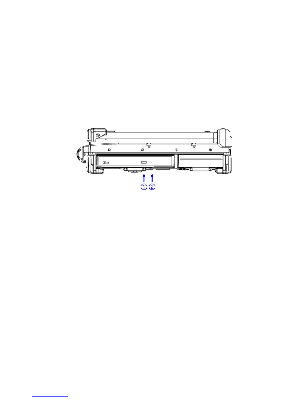
Controls and Indicators (Right)
DVD-ROM Drive Configuration:
1. DVD-ROM eject button
2. DVD-ROM in use
Page 15
Getting Started
5
2nd Battery Configuration: (optional)
No special control or indicator.
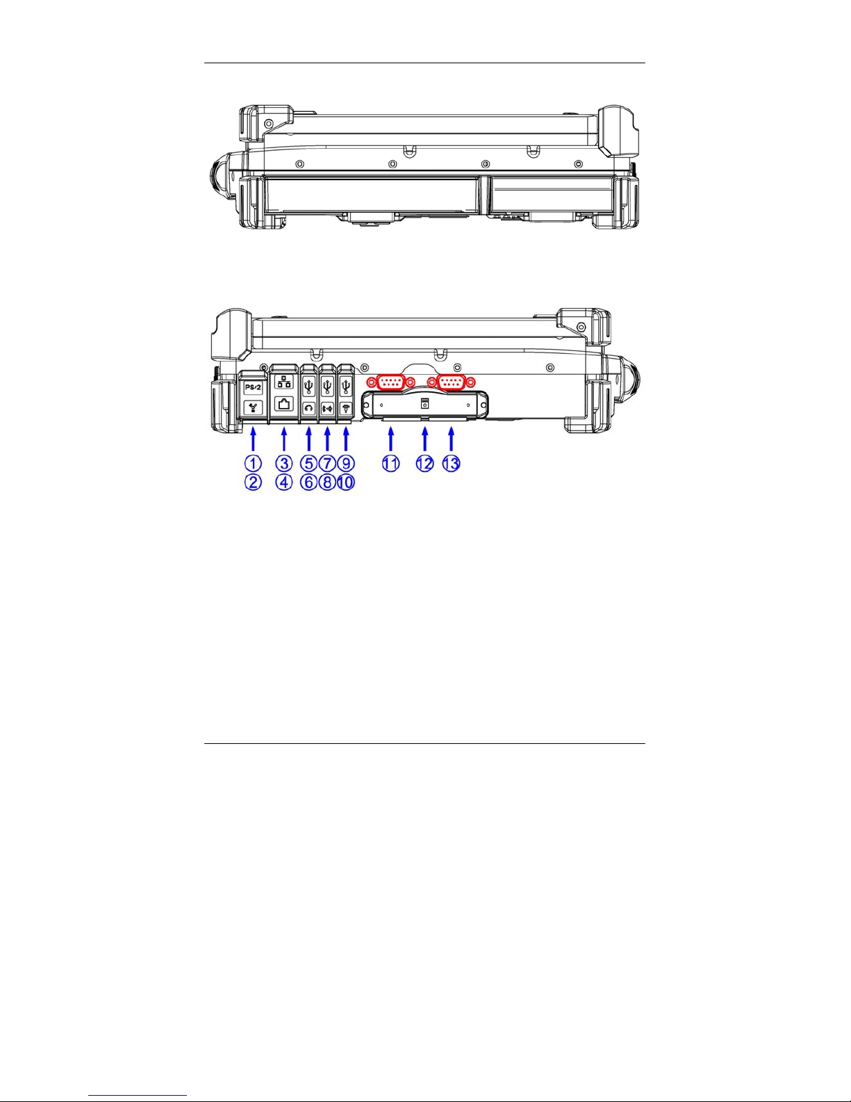
Controls and Indicators (Left)-Standard
1. External Keyboard + PS/2 port/Fiber LAN (Option)
2. IEEE1394 port (Fire Wire)
3. Modem Jack
4. LAN Jack
5. USB port (Universal Serial Bus)
6. External Speaker & Ear phone Jack
7. USB port (Universal Serial Bus)
8. Line In Jack
Page 16
Getting Started
6
9. USB port (Universal Serial Bus)
10. Microphone Jack
11. Optional COM 3 port
12. 1x Express and 1x PCMCIA Slots (Option: 2x PCMCIA)
13. Optional COM 4 port
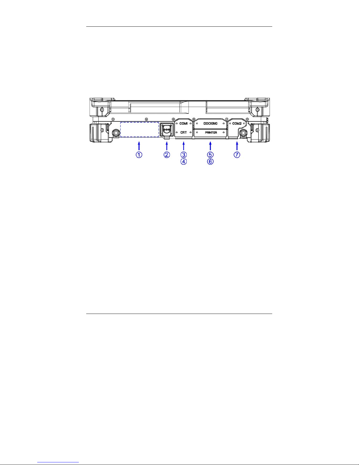
Controls and Indicators (Rear)
1. Optional Military connector port
2. DC Power Jack
3. Serial Port COM1
4. External RGB Port
5. Docking Port
6. Printer Port
7. Serial Port COM2
Page 17

Useful Information
7
USEFUL INFORMATION
Location
A clean and moisture-free environment is preferred. Make room for
air circulation. Avoid areas with:
- Sudden or extreme changes in temperature.
- Extreme heat.
- Strong electromagnetic fields (near television set, motor rotation
area, etc.).
- Dust or high humidity.
If it is necessary to work in a hostile environment, please regularly
maintain your computer by cleaning dust, water, etc. and keep it in
optimal condition.
Ruggedness
The computer is designed with rugged features such as vibration,
shock, dust, and rain/water protection. However, it is still necessary
to provide appropriate protection while operating in harsh
environments.
The computer is designed to withstand rainfall from top with mild
wind blowing only. Please keep the keyboard facing up, i.e. normal
operating direction, to maintain water resistance. NEVER immerse
the unit in water, or spray water at an upside-down system. Doing so
may cause permanent damage.
The D-sub connector caps on the rear of the computer are for dust
and shock protection. The connectors are sealed internally. Other I/O
ports and devices on the left or right must have caps tightly closed or
cable inlets sealed while exposed to water or dust.
There are optional gaskets for DB-9 and DB-25 connectors. You may
install them to improve rain/dust/moisture resistance on your
commercial type cable. Insert the packing into the male connector
(with pins) and fasten the screws.
All connectors will be corroded if exposed to water or moisture.
Page 18

Useful Information
8
Corrosion is accelerated if power is ON. Please take proper waterresistant measures for cable connections.
The DC jack and cables are sealed and may be operated with water
splashing while attached. All port covers should be in place when no
cable is attached.
Operating Systems
The computer is compatible with most operating systems (OS).
However, not all functions are 100% compatible. For example, ACPI,
APM, Smart Battery, etc. are not available on DOS, Windows NT,
and other non-Microsoft OS. Consequently “Standby”,
“Hibernation”, “Battery Gauge”, etc. would not work under such
operating systems.
ACPI: Advanced Configurations and Power Interface
APM: Advanced Power Management
For power consumption and heat dissipative consideration, ACPI
OS (Windows) is highly recommended. Set Power Options
as ”Portable/Laptop” in Control Panel to fully implement the
power management features.
AC Adapter
The AC adapter performs two functions:
- It powers the computer from an external AC source.
- It charges the computer battery.
The adapter automatically detects the AC line voltage (110V or
220V) and adjusts accordingly.
The following are recommended when using the AC adapter:
- Use a properly grounded AC outlet.
- Use one AC outlet exclusively for the computer. Having other
appliances on the same line may cause interference.
- Use a power strip with built- in surge protection.
Page 19

Useful Information
9
Connect the AC adapter:
1. Plug the AC cord to the adapter.
2. Plug the other end of the AC cord into the wall outlet. Make sure
the green LED on the adapter turns on.
3. Attach the DC plug into the power jack of the computer; turn the
lock ring clockwise to secure it.
AC Adapter Indicator
The green LED indicates that AC power is ready.
Battery
The computer will automatically switch to battery when the external
power source (AC adapter or optional vehicle adapter) is
disconnected.
Battery Power Saving Tips
The computer comes with an intelligent power-saving feature. You
may extend the battery life by:
- Setup power saving functions in Operating System Power
Management options (e.g. Windows Power Options).
- Lower the intensity of the display by brightness control.
- Use standby option when computer is temporarily not in use.
- Shut down the computer when it will not be in use for long
periods of time.
Battery Low
When the battery is nearly exhausted, the computer gives the
following “Battery Low” warnings:
- Windows battery low warning (when operating system is
Windows)
Page 20
Useful Information
10
- The power LED flashes.
Once the Battery Low warning occurs, please:
1. Save and close the files you are currently working on.
2. Plug in the AC adapter to recharge the battery.
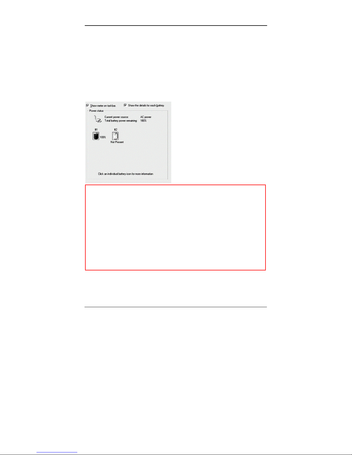
Battery Gauge
You may check battery status from battery gauge in Windows. Click
the power/battery icon to reveal the battery gauge window.
Note: Battery characteristic varies depending on factors such as
ambient temperature, charging method, load current,
aging, etc. For example, the chemicals of the battery are
more inactive at low temperature, thus decreases the
output power.
The battery gauge should only be used as a reference.
Please do not expect it to show the exact amount of the
power remaining. There is no memory effect on Lithium
Ion battery cells. However, discharge the battery to nearly
empty every month will help calibrating the internal
gauge.
Charging the Battery
Plug in the AC adapter (or optional vehicle adapter) to start
Page 21

Useful Information
11
the battery charging. If the battery is already full, the sense circuitry
will stop high current charge within several minutes.
There are two LED indicators next to the power indicator for the
Primary and Secondary battery respectively. Indicator turns ON
when the battery is charging and turns OFF when the battery charge
is completed.
To charge the Secondary Battery, simply install it into the computer
and attach the AC adapter. The internal charger will charge the
Primary and Secondary batteries simultaneously.
Optional Dual Battery Charger can charge Primary and Secondary
batteries externally.
Boot Up and POST
The computer turns ON and loads the operating system (such as
Windows) into the system memory. This start-up procedure is called
“boot up”.
The ROM BIOS Power On Self-Test (POST)
Each time the computer powers on, it automatically performs a selftest of its memory and hardware devices.
Standby/Hibernate/Resume
The system can enter standby or hibernate mode by either pressing
the power switch or staying idle till timeout.
Note: Standby/Hibernate/Resume works with both AC adapter
and battery. The power management functions may not
work under Windows NT or non-Windows operating
systems.
Page 22

Useful Information
12
Shutdown
The following procedure is recommended in shutting down the
computer:
1. Save any work you want to keep.
2. Make sure none of the disk drives are active (HDD and DVD-
ROM drive).
3. Remove any diskettes, DVD-ROMs, or other media if necessary.
4. Follow the shut down procedure of your operating system.
5. Let the computer shut down or push the power switch to turn
OFF.
Failure to shut down the computer properly may result in loss of data
or hardware damages.
Automatic shut down is activated at battery exhaust. Be sure to finish
your work and save all your data when the battery low warning
appears.
RTC
Battery backed up RTC (Real Time Clock/Calendar) is built in an
on-board CMOS (Complementary Metal Oxide Semiconductor) chip.
The RTC keeps track of the time and date while the computer is off.
The CMOS chip also stores system setup information.
RTC battery is also recharged when AC adapter is attached.
Recharge the computer approximately once per month to ensure RTC
operation.
Replacing Modules
Caution: You must turn the power OFF before replacing the
DVD-ROM and HDD modules.
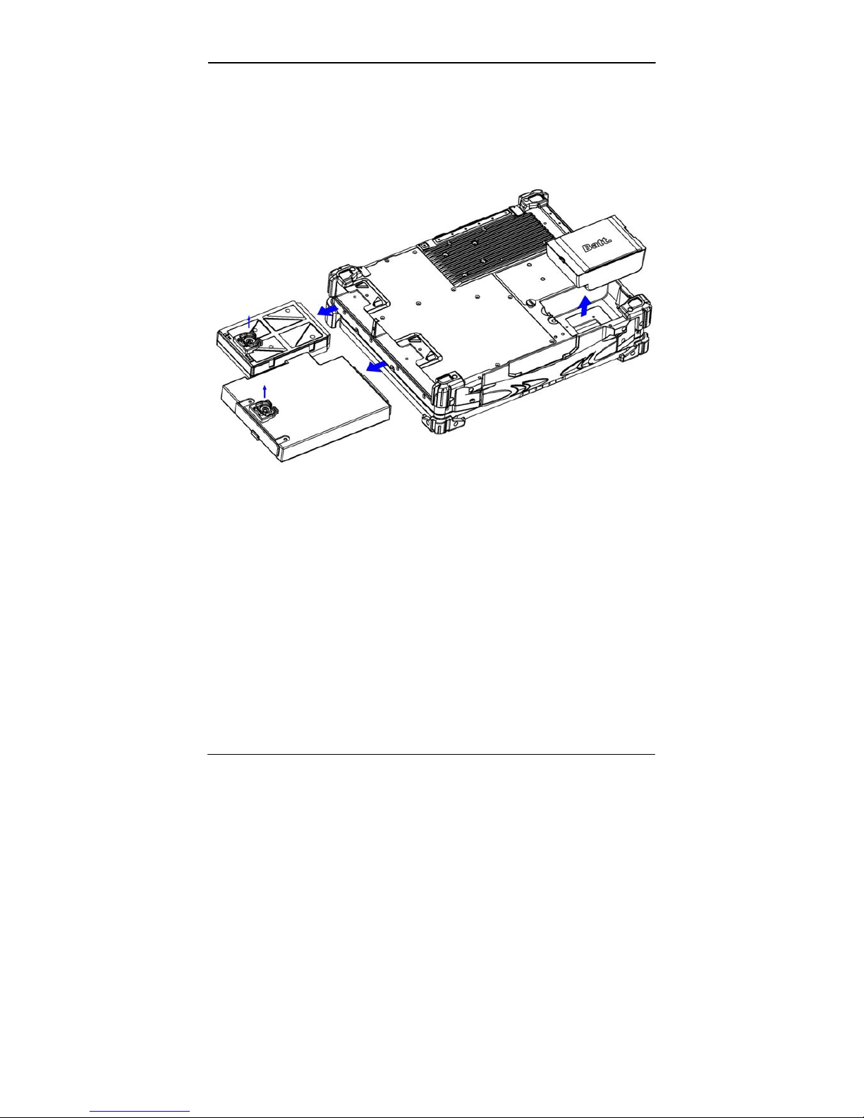
To remove the modules:
1. Turn OFF the computer or hibernate.
2. Disconnect all cables from the computer.
Page 23
Useful Information
13
3. Use a coin to turn and loose the screws on the modules.
4. Remove the battery from the compartment.
5. Push the latch knob to release the DVD-ROM or HDD module
and push them outward.
6. Remove the module from the computer.
To re-install the modules:
Gently push the module into the slot. Fasten the screw to fix the
module.
Page 24
Components and Functions
14
COMPONENTS AND FUNCTIONS
Keyboard
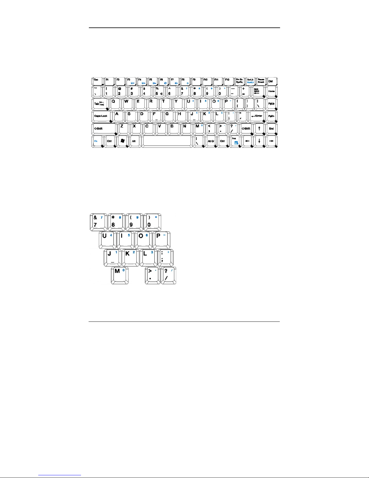
The keyboard is functionally equivalent to a full size desktop
keyboard. A sample key layout is shown below.
The Numeric Keypad
The numeric keypad functions like an electronic calculator. It is
embedded in the main keyboard, with the numeric figures printed on
the upper right of their respective keys. The keypad has keys for the
digits 0~9, the decimal point ( . ), addition ( + ), subtraction ( - ),
multiplication ( * ), and division ( / ).
To activate the keypad, press the Num Lock key. In figure, there are
15 keys which switching from alphabetic to numeric. Press Num
Lock again to return to alphabetic.
Page 25
Components and Functions
15
Keyboard Backlight (optional)
Press [Fn] [F5] key for approximately 1 second turns keyboard
backlight ON or OFF.
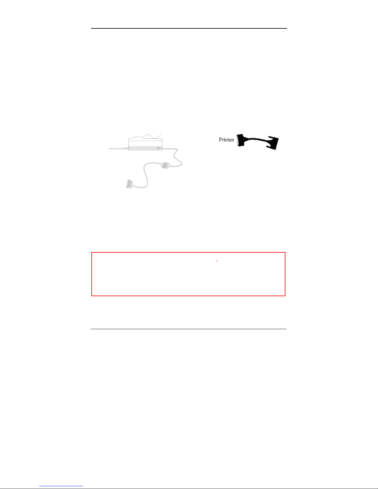
Printer Cable
For most printers there is no special requirement in connection.
However, some printer cables do not contain all 25 wires. To avoid
malfunction, the printer adapter cable comes with your computer
should be attached to the printer cable. The purpose is to re-connect
all the ground pins. Devices equivalent to printer such as scanner,
Lap link cable, etc. also need this cable.
Hard Disk Drive
The Hard Disk Drive (HDD) is a 2.5” type standard SATA interface
data storage device.
HDD and DVD-ROM drives are removable. This provides
convenience and security. They can ONLY be removed while the
power is OFF.
Note: NEVER drop your HDD, DVD-ROM module or expose them
to high temperature, high humidity, or any hazardous
environment. NEVER try to disassemble the module.
Static discharge may destroy your device and data. Always
pick up the modules by touching the case only.
Page 26

Components and Functions
16
DVD-ROM Drive
The DVD-ROM drive is a standard IDE ATAPI type, which accepts
a variety of standard 12cm CDs such as CD-ROM, audio CD, CD-I,
Photo CD, video CD, etc.
The following procedure assumes that all the necessary DVD-ROM
utilities were installed on the computer. For DVD-ROM utility
installation, please refer “Utilities and Drivers”.
DVD-ROM drive also can be removed and swapped with 2nd battery.
Put CD into DVD-ROM drive
While the power is ON, push the DVD-ROM drive’s ejecting button.
The tray will release. Then gently pull the tray out. Put the CD on the
holder and push the tray back into the cabinet. Any dirt on the data
side of the CD may cause read error. Please do not touch this side
when handling CDs.
Read from DVD-ROM drive
The DVD-ROM drive may be designated as drive D: or higher
depending on your configuration. You may access it in DOS or
Windows the same way you would for the floppy disk drive or hard
disk drive. The DVD-ROM is a read-only device. Any command
attempting to write onto it will be denied.
Please avoid shock or vibration while the DVD-ROM drive is active.
Express and PCMCIA Cards
The computer supports one type-II PCMCIA and one Express card or
two type-II PCMCIA cards. To remove the card, push the button on
the right of the card to eject it. The eject button can hide into the
compartment by pushing it inward gently.
Page 27
Components and Functions
17
DockUnder (optional)
DockUnder is utilized for system unit docking. AC adapter or
vehicle adapter attaches directly to DockUnder and automatically
charges the computer while docked.
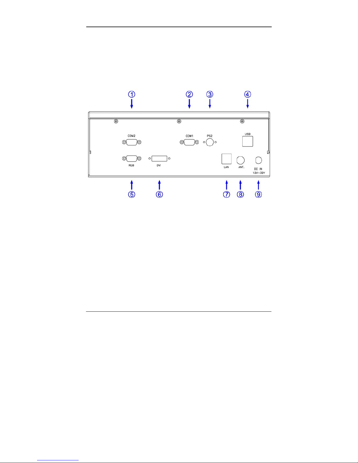
Ports (horizontal version, ports on rear)
1. COM2
2. COM1
3. PS/2
4. USB #1 & #2
5. RGB
6. DVI
7. LAN (Sealed/No function)
8. ANT. (Reserved)
9. DC jack
Page 28
Components and Functions
18
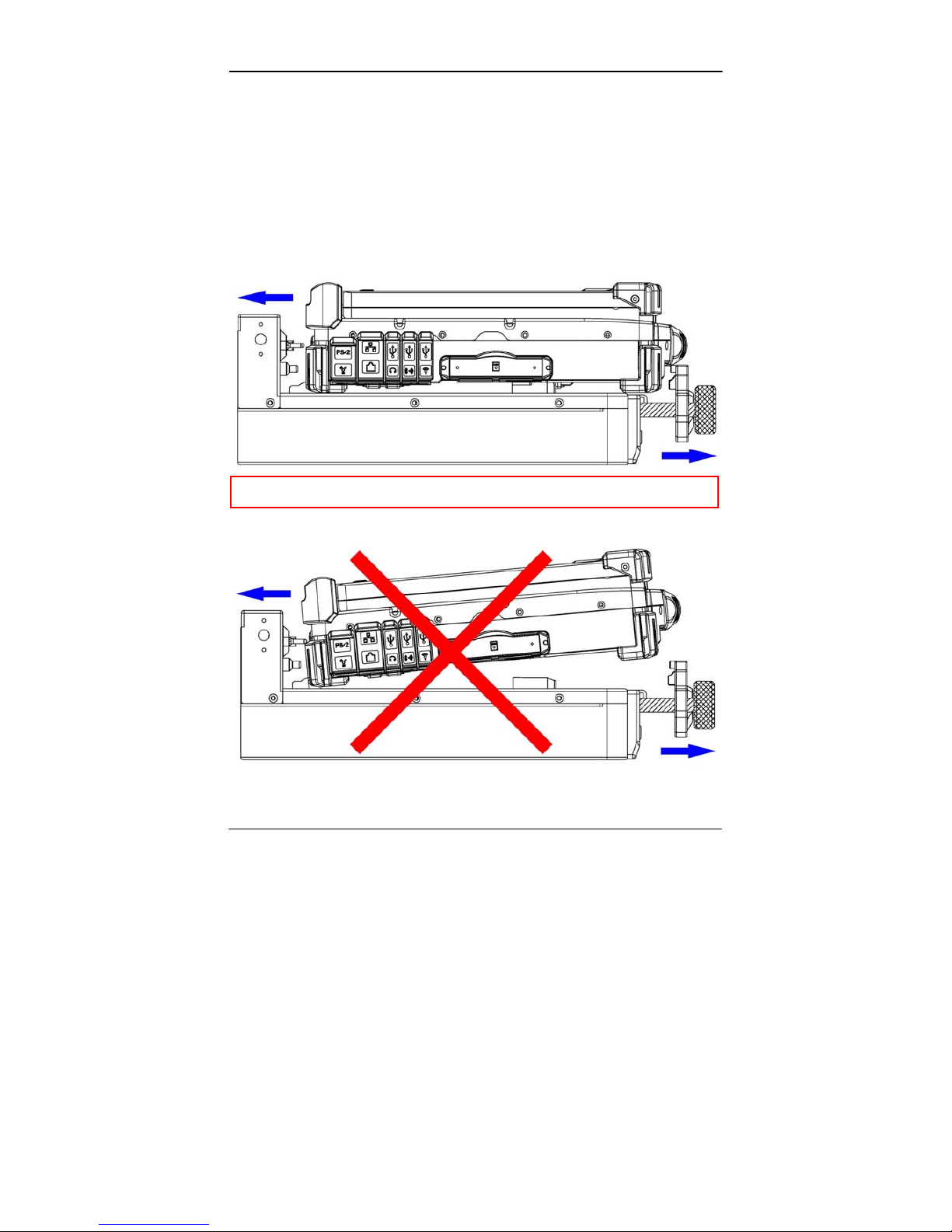
Mount the DockUnder:
1. Turn OFF the power.
2. Open the rubber cap of the docking connector.
3. Align the docking connector.
4. Push the computer to join the guiding pins. Do not lift the
computer up while docking.
5. Metal bar is drawn outward.
Note: Do not lift up the computer while engaging.
Page 29
Components and Functions
19
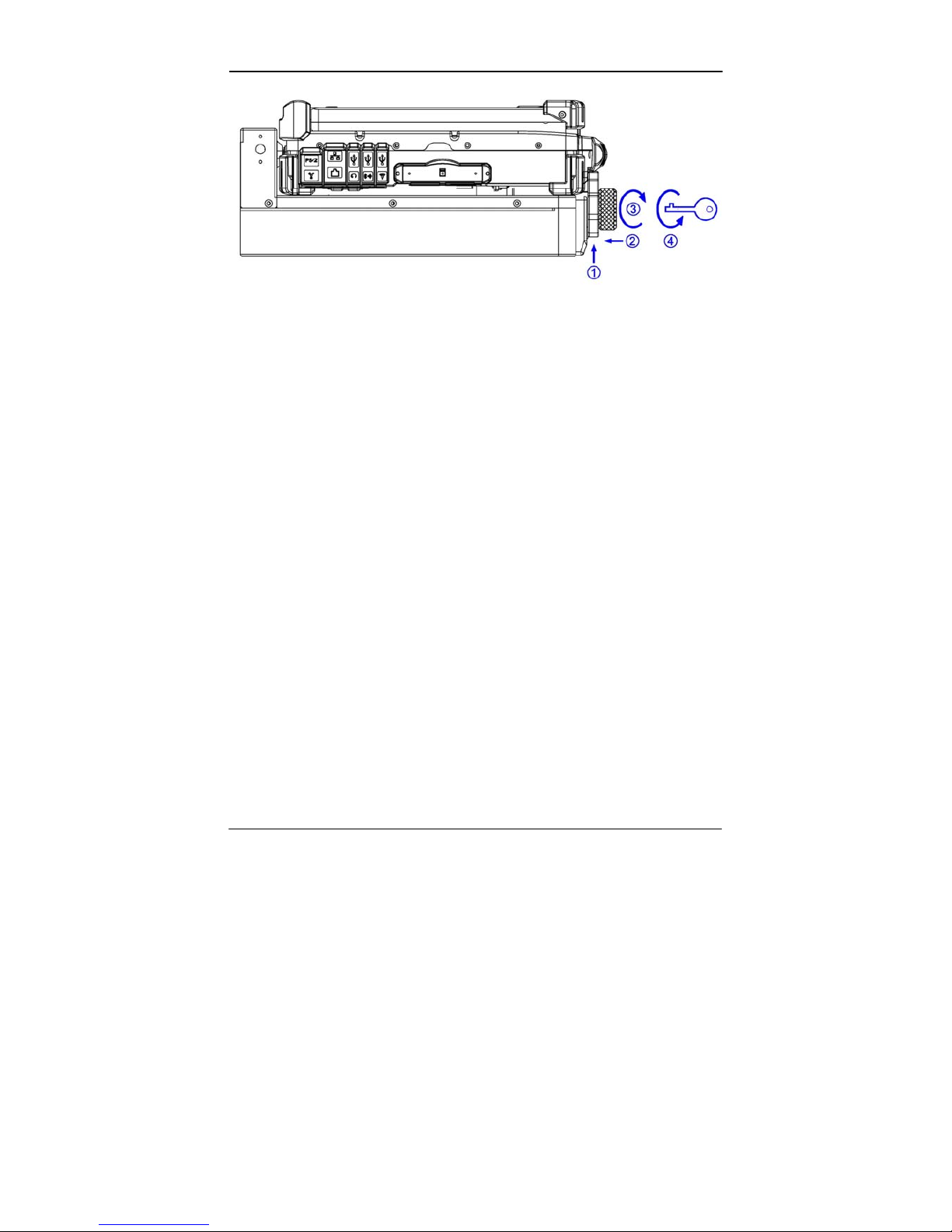
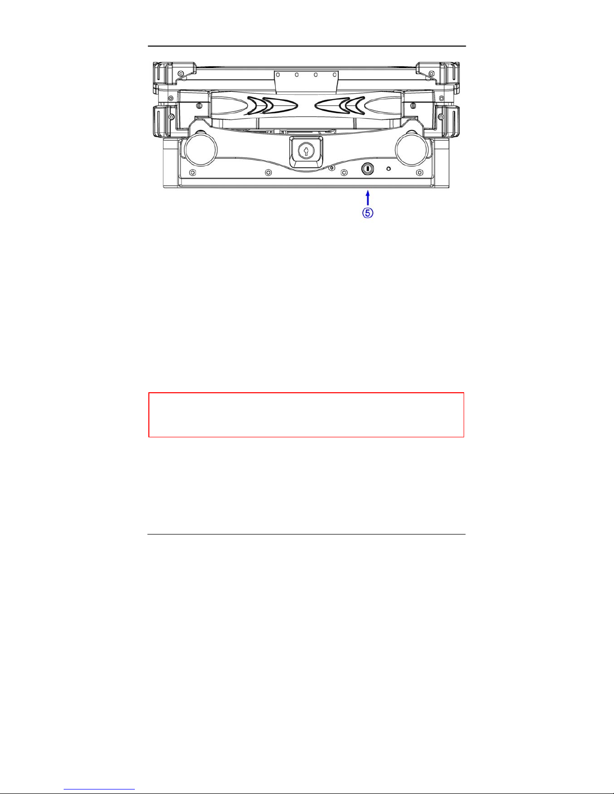
1. Pull up the metal bar.
2. Move forward inside.
3. Lock along the direction of the clock.
4. Key Locked with Electric Power ON/OFF.
While turn on the power of DockUnder with the Key that can use all
the functions on DockUnder. Meantime Computer will also have the
power.
There are 1*PCI+1*PCIe slots on the DockUnder. Maximum card
dimensions are 260mm (L: length, including L-bracket thickness) x
115mm (W: width, including gold fingers) x 25 mm (H: height). The
total power rating of 2 PCI slots is +5V 3A, +3.3V 3A, +12V 300mA,
and -12V 300mA.
Page 30
Components and Functions
20
5. Power On/Off with Computer.
The Power On/Off can be replaced for Computer itself.
To install expansion card in DockUnder:
1. Unplug the AC adapter.
2. Release and remove the computer.
3. Remove the screws on the upper and lower covers.
4. Open the upper cover.
5. Install the expansion card into the slot and fix the L-bracket.
6. Assemble the upper cover.
7. Attach the computer and perform functions test.
Note: Please check IRQ conflict before installing cards and
drivers.
Never dock or un-dock the computer while power is ON.
Page 31

Components and Functions
21
IRQ DMA
0. Timer output 0 0 Sound
1. KB 1 Sound
2. 8 RTC 2 FDD
9 ACPI (or Free) 3 Reserved (or
ECP/EPP)
10 Free (16-bit PCMCIA, or COM3*)
11 PCI devices or Card Bus 0/1 (Sound, LAN*, 32-bit
PCMCIA, etc.)
12 Touch pad (PS/2 mouse)
13 Co-processor
14 HDD
15 DVD-ROM drive
3. COM2 (or Fax/Modem*, IrDA)
4. COM1 (or Touch screen)
5. Free (COM4*)
6. FDD
7. Parallel port 1
*: Optional devices.
Page 32

Optional Devices
22
OPTIONAL DEVICES
Memory Card
The memory card will expand your memory to facilitate better
system performance. The cards are available as following:
1 GB, 2 GB
2nd Battery
A Lithium Ion rechargeable 2nd battery may install into the DVDROM compartment. It has the same capacity of primary battery and
smart battery compliance.
The computer’s internal charger can detect 2nd battery and perform
charging accordingly.
LAN and Fax/Modem Card
10/100/1000 M Base-T Ethernet LAN card for a wired network and
V.90 56K Fax/Modem.
Wireless LAN Card
IEEE 802.11 a.b.g wireless LAN card and rugged antenna.
DVD-RW Drive
Swappable with DVD-ROM drive for DVD playback and writing
CD-R. Backward compatible with DVD-ROM, VCD, etc.
2nd HDD
Swappable with DVD-ROM drive. Set as IDE primary slave drive.
Touch Screen
Resistive touch screens for direct finger touch or pen input instead of
mouse or touch pad.
Page 33

Optional Devices
23
PCMCIA Cover
Besides the attached PCMCIA rubber cover, there is an optional
cover with a metal frame that can be fixed using screws. The cover
provides protection from dust or water for cabled PCMCIA cards.
Users may seal the cable outlet after installation.
Vehicle Adapter
Converts power from car lighters or truck batteries to DC +19V, the
same output ratings as AC adapters. It can power the system and
charge the batteries simultaneously.
Caution: Remove or disconnect the adapter when leaving the
vehicle to avoid battery exhaustion.
Dual Battery Charger
This charger provides two slots for the Primary and Secondary
battery respectively. It accepts power from AC adapter or vehicle
adapter and charges both batteries simultaneously. It takes
approximately 6 hours to fully charge both batteries.
DockUnder
DockUnder RT8-H: (no hot docking)
Serial ports x 2, USB 2.0 x 2, PCI slots x 1, PCIe slot x 1, PS/2, RGB,
DVI.
Ports are on the rear. (LAN option)
Hot docking: Docking while computer power is ON.
Page 34

Specifications
24
SPECIFICATIONS
CPU
Intel Core2 Duo (Merom)
CPU runs at multiple speeds dependent on CPU type and operating
system:
The CPU speed switches automatically by detecting AC adapter/
battery operation and busy state.
Memory
System memory Standard: 1GB
Expandable: 4GB (2GBx 2)
Cache memory Internal Level-2 2MB
Video memory 224MB (shared RAM)
Notes:
- For standard embedded VGA version, the usage is
approximately 3.2GB only when installed 4GB RAM.
- For optional MXM VGA version, maximum installation is
3.0GB.
That is because BIOS reserved address space from 3.2GB to
4.0GB as buffers for PCI devices.
Display
The display is a XGA compatible LCD (Liquid Crystal Display) of
1024 x 768 dots (horizontal x vertical) or SVGA 800 x 600 dots with
16, 24 or 32 bit color depth. The computer is capable of displaying
2048 x 1536 dots on the LCD external monitor.
LCD:
Type: 13.3” Active TFT Color
Page 35

Specifications
25
Resolution: 1024 x 768 pixels (13.3”)
Mode: VGA, EGA, MGA, SVGA, and XGA
Color: 16, 24 or 32-bit color depths on all modes
Characters x Row: 80 x 25
Keyboard
Number of keys: 87
Key travel: 2.5 mm (standard)
1.5 mm (optional backlight)
Function: Emulates standard 101/102-key keyboard
Hard Disk Drive
Type: 2.5”
Interface: Serial ATA
Touch Screen
Type: Resistive
Interface: Serial
Resolution: >1024x1024
I/O ports
- 2x Serial ports
- External RGB monitor port
- External PS/2+Keyboard port
- Audio ports (External Speaker/Earphone, Microphone, Line-in)
- RJ11 Phone jack for internal Fax/Modem (optional)
- RJ45 jack for internal LAN card (optional)
- 1x Express and 1x PCMCIA Slots (Option: 2x PCMCIA)
- Printer port
- Docking port
Page 36

Specifications
26
- 3xUSB 2.0 port
- 1x1394 port
- 2x optional serial port
- 1x optional military connector port
AC Adapter
Voltage: AC 90~240 V
Frequency: 50/60 Hz
Output Voltage: DC 19V
Maximum Power: 90 Watts
Dimension: 130mm (W) x 60mm (D) x 34mm (H)
Weight: 430 g (0.9 lb.)
Vehicle Adapter
Input Voltage 12V/24V (12~32V) Auto-sense
Input Current 2.5A/5.5A max. (12V/24V respectively)
Output Voltage 19V +/-5%
Output Current 4A
Wiring Cigarette lighter/Truck battery
Application Car or Truck installation
Battery
Primary Battery:
Type: 9 x 18650 cells Lithium Ion
Capacity: 11.1V 7200mAH
Dimension: 103 mm (W) x 73 mm (D) x 38 mm (H)
Weight: 435 g (0.95 1b.)
2nd Battery (optional):
Type: 9 x 18650 cells Lithium Ion
Page 37

Specifications
27
Capacity: 11.1V 7200mAH
Dimension: 150 mm(W) x 90 mm(D) x 20 mm(H)
Weight: 560 g (1.2 1b.)
System Unit Dimensions and Weight
Width: 312mm (12.3”)
Depth: 246mm (9.7”)
Height: 66.7mm (2.6”)
Weight: 4.3Kg
(9.5 lb. including DVD-ROM drive and
primary battery)
Note: Weight varies depending on system configurations.
Materials and Recycling
Materials of the computer are as follows:
Cabinet: Magnesium alloy AZ91D,
UL grade PC+ABS GE C6200 or TN-3813BW
Bracket: Aluminum 5052, steel with nickel plating, or stainless
steel S304
Cushion pad: Rubber
PCB: FR-4, UL 94V0
Battery: Rechargeable Lithium Ion, 9 cells per pack
Packing: Carton: Unbleached paper
Cushion: Recyclable EPE
Carrying bag: Recyclable PE fiber
User's Guide: Recycled/recyclable paper
Please recycle the parts according to local regulations.
Page 38

Specifications
28
Environmental
Temperature: -20 ~ 50ºC (32 ~ 122ºF) operating
-40 ~ 70ºC (-40 ~ 158ºF) storage
Humidity: 5~95% Non-condensing operating
95% maximum storage
Altitude: 0 ~ 4,572 meters (0 ~ 15,000 feet) operating
Page 39
BIOS Setup
29
BIOS SETUP
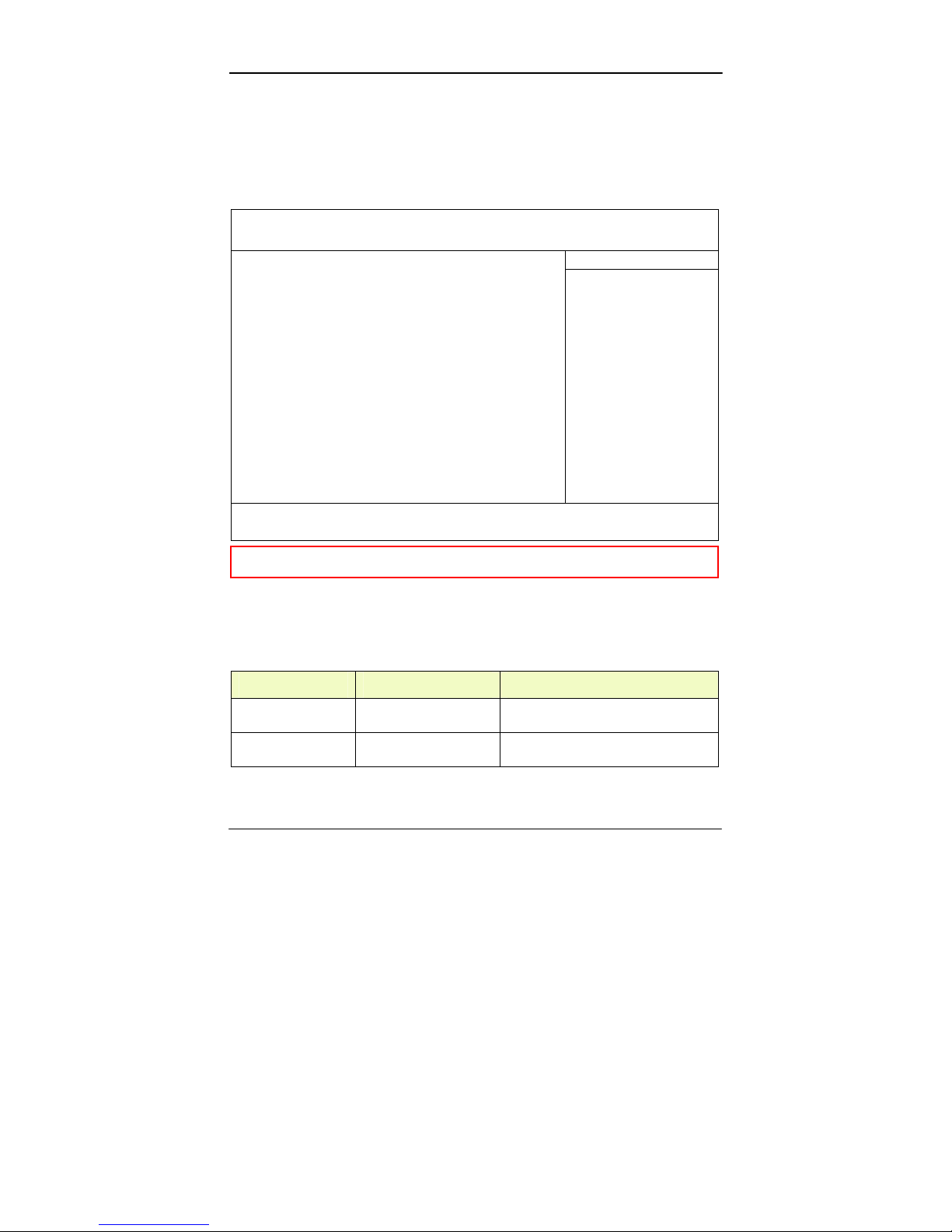
Press [F2] at boot up to enter BIOS setup. Use arrow keys to select
options and [+/-] to modify them. When finished, move to ”Exit” and
press [Enter] then confirm save by pressing [Y].
Main Menu
Phoenix TrustedCore (tm) Setup Utility
Main Advanced Security TPM State Boot Exit
Item Specific Help
System Time: [16:19:20]
System Date: [03/02/2007]
Legacy Diskette A: [1.44/1.25MB 3½"]
• IDE Channel 0 Master [None]
• IDE Channel 0 Slave [None]
• IDE Channel 1 Master [None]
• IDE Channel 1 Slave [None]
System Memory: 640 KB
Extended Memory: 1038336 KB
<Tab>, <Shift-Tab>, or
<Enter> selects field.
F1 Help ↑↓ Select Item –/+ Change Values F9 Setup Defaults
Esc Exit ↔ Menu Enter Select ► Sub-Menu F10 Save and Exit
Note: The contents may vary depending on computer configurations.
Main Menu Selections
You can make the following selections on the Main Menu. Use the
sub-menus for other selections.
Feature Options Description
System Time HH:MM:SS Set the system time Hour, Minute,
Second.
System Date MM/DD/YYYY Set the system date Month, Day,
Year.
Page 40

BIOS Setup
30
Feature Options Description
Legacy Diskette A Disabled
360 Kb 5¼"
1.2 MB 5¼"
720 Kb 3½"
1.44/1.25 MB 3½"
2.88 MB 3½"
Select floppy type. Note that 1.25 MB
3½” references a 1024 byte/sector
Japanese media format. The 1.25MB,
3½" diskette requires a 3-Mode
floppy-disk drive.
Page 41
BIOS Setup
31
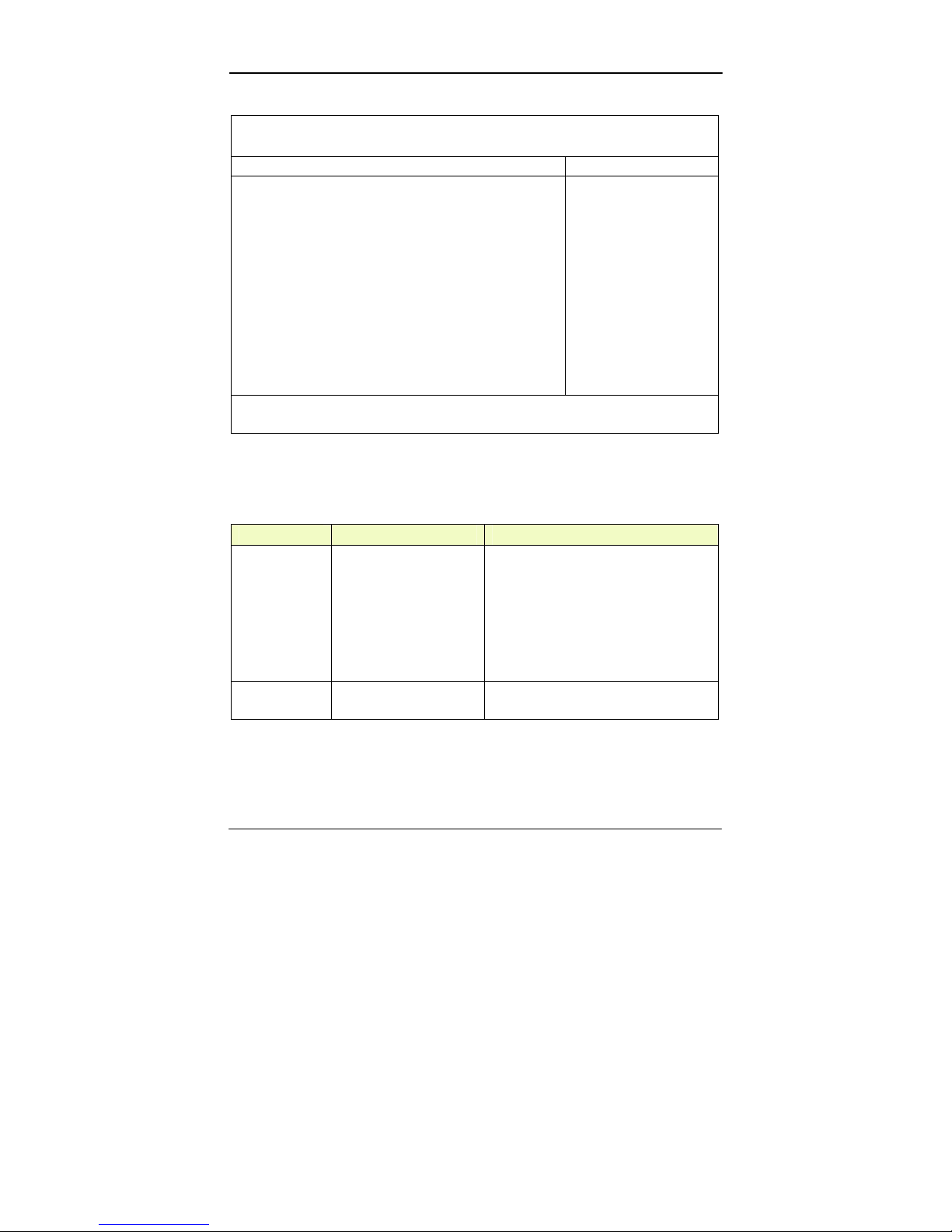
IDE Channel 0 Master Sub-Menu
Phoenix TrustedCore (tm) Setup Utility
Main
IDE Channel 0 Master [None] Item Specific Help
Type: [Auto]
LBA Format
Total Sectors: 78140160
Maximum Capacity: 40008MB SATA1
Multi-Sector Transfers: [Disabled]
LBA Mode Control: [Disabled]
32 Bit I/O: [Disabled]
Transfer Mode: [Standard]
Ultra DMA Mode: [Disabled]
User = you enter
parameters of hard-disk
drive installed at this
connection.
Auto = autotypes harddisk drive installed here.
CD-ROM = a CD-ROM
drive is installed here.
ATAPI Removable =
removable disk drive is
installed here.
F1 Help ↑↓ Select Item –/+ Change Values F9 Setup Defaults
Esc Exit ↔ Menu Enter Select ► Sub-Menu F10 Save and Exit
IDE Channel 0 Master Sub-Menu Selections
You can make the following selections on the IDE Channel 0 Master
Sub-Menu.
Feature Options Description
Type User
Auto
CD-ROM
ATAPI Removable
User = you enter parameters of hard-disk
drive installed at this connection.
Auto = autotypes hard disk drive
installed here.
CD-ROM = a CD-ROM drive is
installed here.
ATAPI Removable = removable disk
drive is installed here.
32 Bit I/O Disabled
Enabled
This setting enables or disables 32 bit
IDE data transfers.
Page 42
BIOS Setup
32
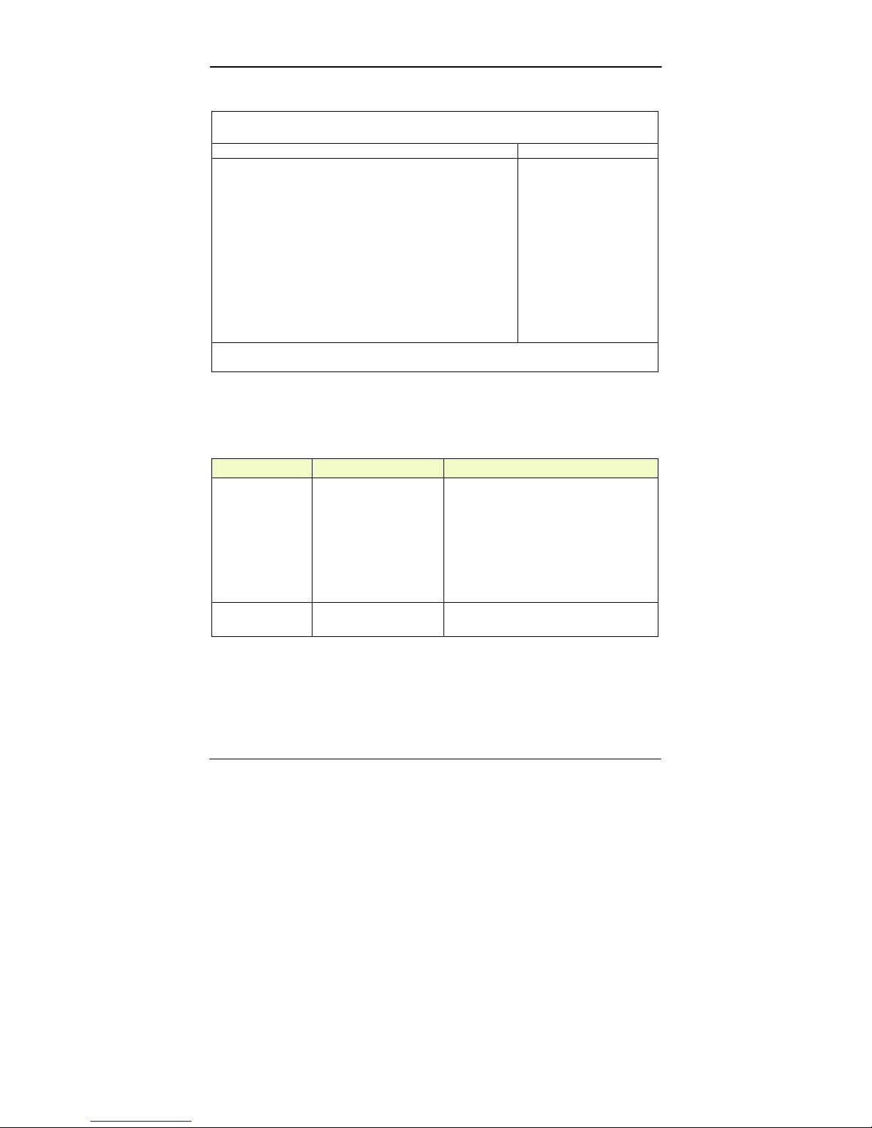
IDE Channel 0 Slave Sub-Menu
Phoenix TrustedCore (tm) Setup Utility
Main
IDE Channel 0 Slave [None] Item Specific Help
Type: [Auto]
Multi-Sector Transfers: [Disabled]
LBA Mode Control: [Disabled]
32 Bit I/O: [Disabled]
Transfer Mode: [Standard]
Ultra DMA Mode: [Disabled]
SMART Monitoring: Disabled
User = you enter
parameters of hard-disk
drive installed at this
connection.
Auto = autotypes harddisk drive installed here.
CD-ROM = a CD-ROM
drive is installed here.
ATAPI Removable =
removable disk drive is
installed here.
F1 Help ↑↓ Select Item –/+ Change Values F9 Setup Defaults
Esc Exit ↔ Menu Enter Select ► Sub-Menu F10 Save and Exit
IDE Channel 0 Slave Sub-Menu Selections
You can make the following selections on the IDE Channel 0 Slave
Sub-Menu.
Feature Options Description
Type User
Auto
CD-ROM
ATAPI Removable
User = you enter parameters of hard-disk
drive installed at this connection.
Auto = autotypes hard disk drive
installed here.
CD-ROM = a CD-ROM drive is
installed here.
ATAPI Removable = removable disk
drive is installed here.
32 Bit I/O
Disabled
Enabled
This setting enables or disables 32 bit
IDE data transfers.
Page 43
BIOS Setup
33
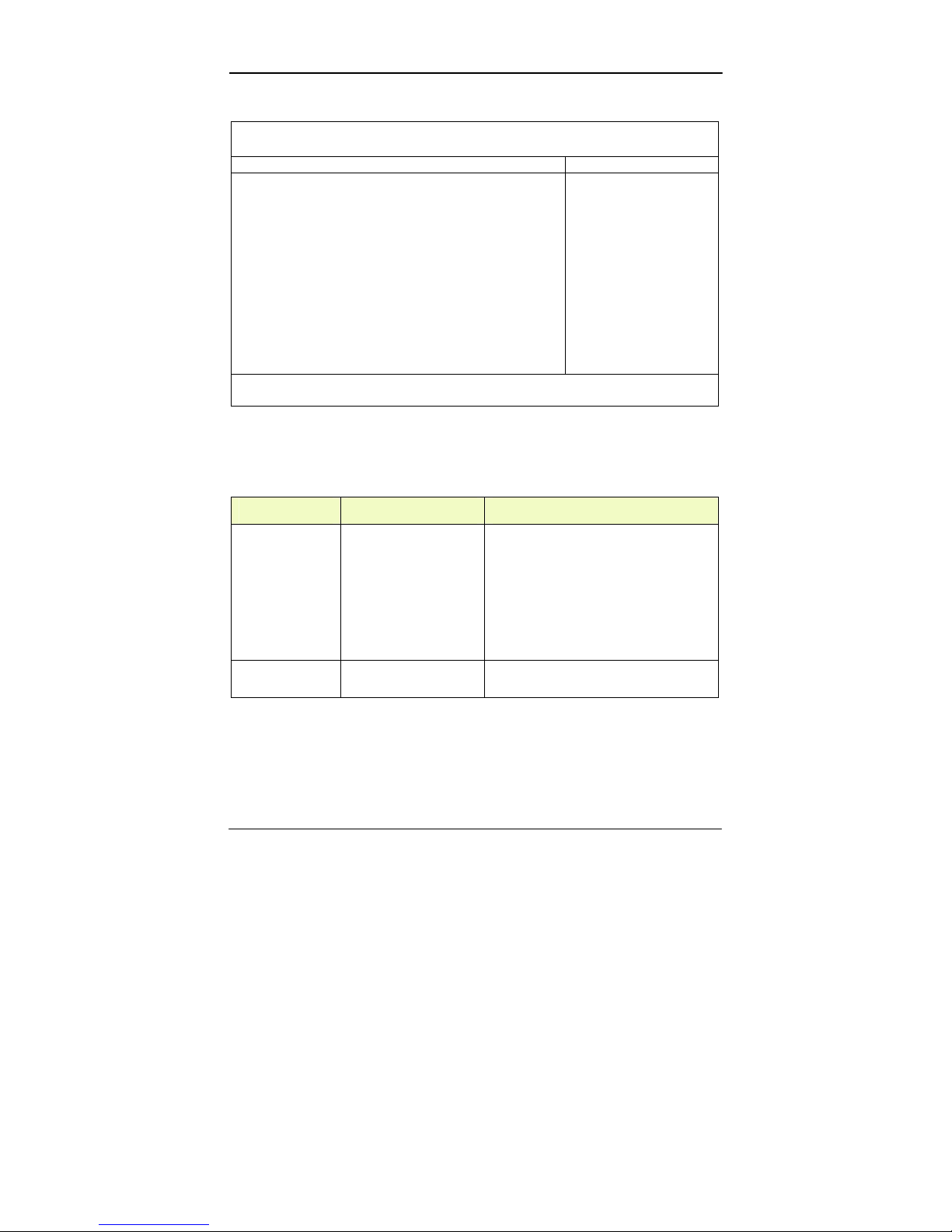
IDE Channel 1 Master Sub-Menu
Phoenix TrustedCore (tm) Setup Utility
Main
IDE Channel 1 Master [None] Item Specific Help
Type: [Auto]
Multi-Sector Transfers: [Disabled]
LBA Mode Control: [Disabled]
32 Bit I/O: [Disabled]
Transfer Mode: [Standard]
Ultra DMA Mode: [Disabled]
User = you enter
parameters of hard-disk
drive installed at this
connection.
Auto = autotypes harddisk drive installed here.
CD-ROM = a CD-ROM
drive is installed here.
ATAPI Removable =
removable disk drive is
installed here.
F1 Help ↑↓ Select Item –/+ Change Values F9 Setup Defaults
Esc Exit ↔ Menu Enter Select ► Sub-Menu F10 Save and Exit
IDE Channel 1 Master Sub-Menu Selections
You can make the following selections on the IDE Channel 1 Master
sub-menu.
Feature Options Description
Type User
Auto
CD-ROM
ATAPI Removable
User = you enter parameters of hard-disk
drive installed at this connection.
Auto = autotypes hard disk drive
installed here.
CD-ROM = a CD-ROM drive is
installed here.
ATAPI Removable = removable disk
drive is installed here.
32 Bit I/O Disabled
Enabled
This setting enables or disables 32 bit
IDE data transfers.
Page 44
BIOS Setup
34
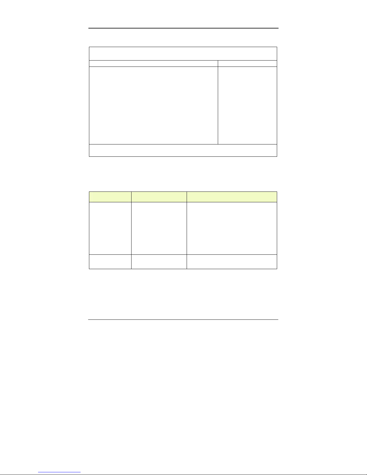
IDE Channel 1 Slave Sub-Menu
Phoenix TrustedCore (tm) Setup Utility
Main
IDE Channel 1 Slave [None] Item Specific Help
Type: [Auto]
Multi-Sector Transfers: [Disabled]
LBA Mode Control: [Disabled]
32 Bit I/O: [Disabled]
Transfer Mode: [Standard]
Ultra DMA Mode: [Disabled]
User = you enter
parameters of hard-disk
drive installed at this
connection.
Auto = autotypes harddisk drive installed here.
CD-ROM = a CD-ROM
drive is installed here.
ATAPI Removable =
removable disk drive is
installed here.
F1 Help ↑↓ Select Item –/+ Change Values F9 Setup Defaults
Esc Exit ↔ Menu Enter Select ► Sub-Menu F10 Save and Exit
IDE Channel 1 Slave Sub-Menu Selections
You can make the following selections on the IDE Channel 1 Slave
sub-menu.
Feature Options Description
Type User
Auto
CD-ROM
ATAPI Removable
User = you enter parameters of hard-disk
drive installed at this connection.
Auto = autotypes hard disk drive
installed here.
CD-ROM = a CD-ROM drive is
installed here.
ATAPI Removable = removable disk
drive is installed here.
32 Bit I/O Disabled
Enabled
This setting enables or disables 32 bit
IDE data transfers.
Page 45

BIOS Setup
35
General Help Window
Pressing <F1> or <Alt-H> on any menu brings up the General Help
window that describes in detail the keys and functions for setup.
The scroll bar on the right of any window indicates that there is more
than one page of information in the window. Use <PgUp> and
<PgDn> to display all the pages. Pressing <Home> and <End>
displays the first and last page. Pressing <Enter> displays each page
and then exits the window. Press <Esc> to exit the current window.
Page 46
BIOS Setup
36
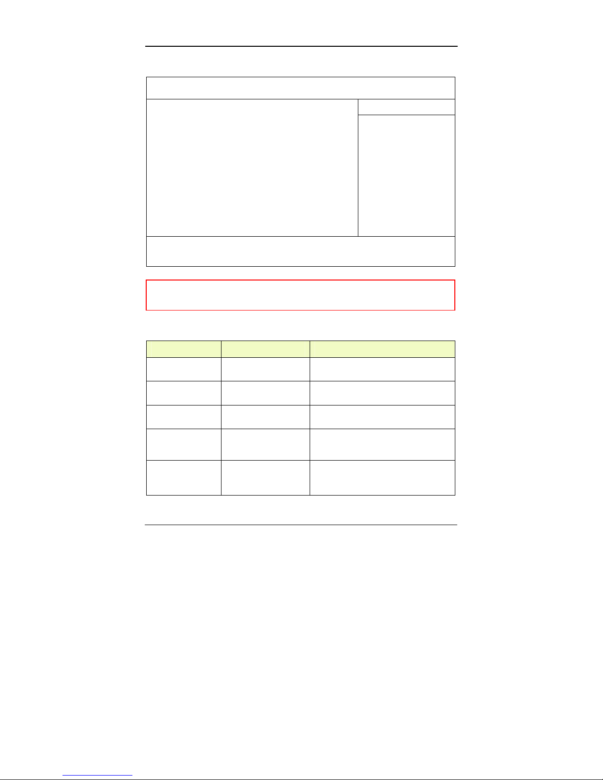
Advanced Menu
Phoenix TrustedCore (tm) Setup Utility
Main Advanced Security TPM State Boot Exit
Item Specific Help
Legacy USB Support: [Enabled]
Summary screen: [Disabled]
Boot-time Diagnostic Screen: [Enabled]
QuickBoot Mode: [Enabled]
Extended Memory Testing [Just zero it]
IGD - Boot Type: [VBIOS
Default]
PS/2 Mouse [Auto Detect]
PCI Express - Root Port 1: [Enabled]
USB - Device 29, Function 7: [Enabled]
Passive Cooling Trip Point [Disabled]
• SIO SMC227 CONFGURATION
Enable support for
Legacy Universal Serial
Bus
F1 Help ↑↓ Select Item –/+ Change Values F9 Setup
Defaults
Esc Exit ↔ Menu Enter Select ► Sub-Menu F10 Save and Exit
Warning: Incorrect settings may cause system malfunction. To
correct it, restore the Setup Defaults with <F9>.
Advanced Menu Selections
You can make the following selections on the Advanced Menu.
Feature Options Description
Legacy USB
Support
Disabled
Enable
Enable support for Legacy Universal
Serial Bus
Summary screen Disabled
Enable
Display system configuration on boot
Boot-time
Diagnostic Screen
Disabled
Enable
Display the diagnostic screen during
boot
QuickBoot Mode Disabled
Enable
Allows the system to skip certain tests
while booting. This will decrease the
time needed to boot the system.
Extended Memory
Testing
Normal
Just zero it
None
Determines which type of tests will be
performed on extended memory (above
1M).
Page 47
BIOS Setup
37
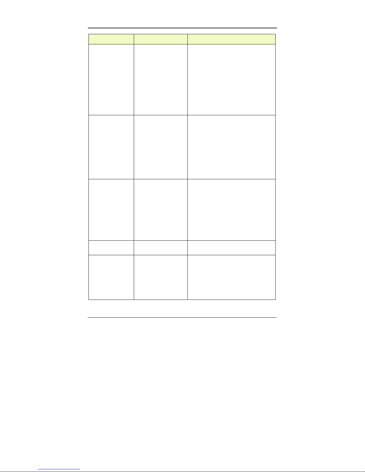
Feature Options Description
IGD - Boot Type VBIOS Default
CRT
LFP
CRT+LFP
TV
LFP-SDVO
EFP
TV-SDVO
CRT+LFP-SDVO
CRT+EFP
Select the Video Device that will be
activated during POST
PS/2 Mouse Disabled
Enable
Auto Detect
’Disabled’ prevents any installed PS/2
mouse from functioning, but frees up
IRQ 12.
’Enabled’ forces the PS/2 mouse port to
be enabled regardless if a mouse is
present.
’Auto Detect’ will enable the PS/2
mouse only if present.
’OS Controlled’ only displayed if the
OS controls the mouse.
PCI Express - Root
Port 1
Disabled
Enable
Auto
Control the PCI Express Port via this
setup option.
Disabled - Port always disabled.
Enabled - Port always enabled.
Auto - Only enable if card found.
Note that if Root Port 1 is disabled,
Root Ports 2-4 will be disabled as well.
USB - Device 29,
Function 7
Disabled
Enable
Control USB 2.0 functionality through
this Setup Item
Passive Cooling
Trip Point
Disabled
15 C/23 C/31 C/39 C/
47 C/55 C/63 C/71 C/
79 C/87 C/95 C/103 C/
109 C/111C
This value controls the temperature of
the ACPI Passive Trip Point – the point
in which the OS will begin throttling the
CPU.
Note: When the DTS is enabled, only
values below 97C are valid.
Page 48

BIOS Setup
38
Feature Options Description
SIO SMC227
CONFGURATION
These items control the configuration of
various National 393 SIO devices.
Page 49
BIOS Setup
39
For most frequently altered setup “SIO SMC227 Configuration”,
please refer following:
Warning: Make sure internal COMx mode settings must be with
the same type of the external connected devices.
Otherwise it may cause serial components damage in
either side.
SIO SMC227 Configuration Sub-Menu
Phoenix TrustedCore (tm) Setup Utility
Advanced
SIO SMC227 CONFIGURATION Item Specific Help
COM1 port: [3F8-IRQ 4]
COM1 mode: [RS232]
COM2 port: [2F8-IRQ 3]
COM2 mode: [RS232]
COM3 port: [3E8-IRQ 10]
COM3 mode: [RS232]
COM4 port: [2E8-IRQ 5]
COM4 mode: [RS232]
Printer1: [378-IRQ 7]
Printer1 mode: [Standatd]
Printer2: [378-IRQ 7]
Configure COM1 using
device options:
[Disabled]
No configuration
[3F8-IRQ 4]
Set the base I/O
address for COM1
F1 Help ↑↓ Select Item –/+ Change Values F9 Setup Defaults
Esc Exit ↔ Menu Enter Select ► Sub-Menu F10 Save and Exit
SIO SMC227 Configuration Sub-Menu Selections
You can make the following selections on the SIO SMC227
Configuration sub-menu.
Feature Options Description
COM1 port Disabled
3F8-IRQ 4
Configure COM1 using device options:
[Disabled]
No configuration
[3F8-IRQ 4]
Set the base I/O address for COM1
Page 50
BIOS Setup
40
Feature Options Description
COM1 mode RS232
TTL1
Configure UART mode options:
[RS332]:External Device
[TTL1]:Internal Device
COM2 port Disabled
2F8-IRQ 3
Configure COM2 using device options:
[Disabled]
No configuration
[2F8-IRQ 3]
Set the base I/O address for COM2
COM2 mode RS232
TTL2
Configure UART mode options:
[RS232]:External Device
[TTL2]:Internal Device
COM3 port Disabled
3E8-IRQ 10
Configure COM3 using device options:
[Disabled]
No configuration
[3E8-IRQ 10]
Set the base I/O address for COM3
COM3 mode RS232
TTL3
Configure UART mode options:
[RS232]:External Device
[TTL3]:Internal Device
COM4 port Disabled
2E8-IRQ 5
Configure COM4 using device options:
[Disabled]
No configuration
[2E8-IRQ 5]
Set the base I/O address for COM4
COM4 mode RS232
TTL4
Configure UART mode options:
[RS232]:External Device
[TTL4]:Internal Device
Page 51
BIOS Setup
41
Feature Options Description
Printer1 Disabled
378-IRQ 4
Configure Printer1 device options:
[Disabled]
No configuration
[378-IRQ 7]
Set the base I/O address for Printer1
Printer1 mode Standard
ECP
EPP
Configure Printer1 mode options:
Standard
EPP
ECP
Printer2 Disabled
3BC
Configure Printer2 device options:
[Disabled]
No configuration
[3BC]
Set the base I/O address for Printer2
Page 52

BIOS Setup
42
Security Menu
Warning: If you forget user/supervisor password, the computer
has to send back to manufacturer and replace EEPROM
to make it work again.
Phoenix TrustedCore (tm) Setup Utility
Main Advanced Security TPM State Boot Exit
Item Specific Help
Processor Serial Number [Disabled]
Set Supervisor Password [Enter]
Set User Password [Enter]
Fixed disk boot sector: [Normal]
Diskette access: [Supervisor]
Password on boot: [Disabled]
USB Interface: [Enabled]
AC97 Audio Interface: [Auto]
AC97 Modem Interface: [Auto]
Cardbus/1394 Interface [Auto]
• RF Security Control:
Controls detection of
Processor Serial No.
System must be reset or
restarted from power-on
for settings to take effect.
F1 Help ↑↓ Select Item –/+ Change Values F9 Setup Defaults
Esc Exit ↔ Menu Enter Select ► Sub-Menu F10 Save and Exit
Security Menu Selections
You can make the following selections on the Security Menu.
Feature Options Description
Processor Serial
Number
Disabled
Enabled
Controls detection of Processor
Serial No. System must be reset or
restarted from power-on for
settings to take effect.
Set Supervisor
password
Enter New Password
Confirm New Password
Supervisor Password controls
access to the setup utility.
Set User Password Enter New Password
Confirm New Password
User Password controls access to
the system at boot.
Fixed disk boot
sector
Normal
Write Protect
Write protects boot sector on the
hard disk to protect against viruses.
Page 53
BIOS Setup
43
Feature Options Description
Diskette access Supervisor Control access to diskette drives
Password on boot Disabled
Enabled
Enables password entry on boot
USB Interface Disabled
Enabled
Control the listed USB Functions
by setting the item to the desired
value.
AC97 Audio
Interface
Disabled
Auto
Control Detection of the AC97
Audio Device.
Auto = AC97 Audio will be
enabled if present, disabled
otherwise.
Disabled = AC97 Audio will be
unconditionally disabled,
regardless of presence.
AC97 Modem
Interface
Disabled
Auto
Control Detection of the AC97
Modem Device.
Auto = AC97 Modem will be
enabled if present, disabled
otherwise.
Disabled = AC97 Modem will be
unconditionally disabled,
regardless of presence.
Cardbus/1394
Interface
Disabled
Auto
Cardbus Device Function
Disable/Enable
RF Security Control RF Security Control:
Wireless LAN
GPRS
GPS
Blue Tooth
Page 54
BIOS Setup
44
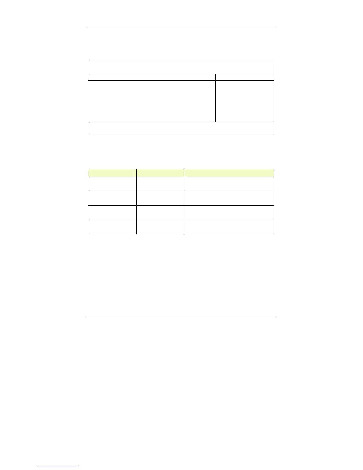
For most frequently altered setup “RF Security Control” please refer
following:
RF Security Control Sub-Menu
Phoenix TrustedCore (tm) Setup Utility
Security
RF Security Control: Item Specific Help
Wireless Lan: [Disabled]
GPRS: [Disabled]
GPS: [Disabled]
Blue Tooth: [Disabled]
Wireless Lan Control
F1 Help ↑↓ Select Item –/+ Change Values F9 Setup Defaults
Esc Exit ↔ Menu Enter Select ► Sub-Menu F10 Save and Exit
RF Security Control Sub-Menu Selections
You can make the following selections on the RF Security Control
sub-menu.
Feature Options Description
Wireless Lan Disabled
Enabled
Wireless Lan Control
Enabled Wireless function
GPRS Disabled
Enabled
GPRS Control
Enabled GPRS function
GPS Disabled
Enabled
GPS Control
Enabled GPS function
Blue Tooth Disabled
Enabled
Blue Tooth Control
Enabled Blue Tooth function
Page 55
BIOS Setup
45
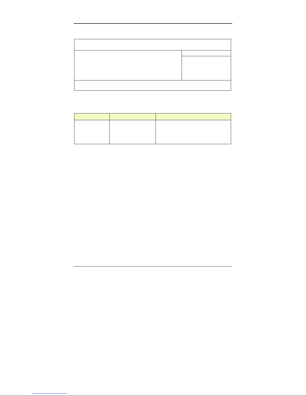
TPM State Menu
Phoenix TrustedCore (tm) Setup Utility
Main Advanced Security TPM State Boot Exit
Item Specific Help
Current TPM State: Enabled and Deactivated
Change TPM State: [No Change]
Change TPM State
F1 Help ↑↓ Select Item –/+ Change Values F9 Setup Defaults
Esc Exit ↔ Menu Enter Select ► Sub-Menu F10 Save and Exit
TPM State Menu Selections
You can make the following selections on the TPM State Menu.
Feature Options Description
Change TPM
State
No Change
Enable & Activate
Deactivate & Disable
Clear
Change TPM State
Page 56
BIOS Setup
46
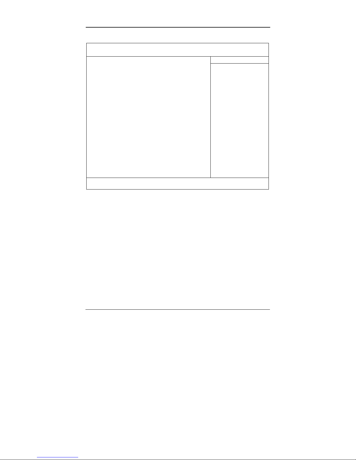
Boot Menu
Phoenix TrustedCore (tm) Setup Utility
Main Advanced Security TPM State Boot Exit
Item Specific Help
Boot priority order:
1: USB KEY:
2: USB FDC:
3: IDE CD:
4: IDE HDD:
5: Legacy network Card
6: Legacy Floppy Drives
7: PCI SCSI:
8:
Excluded from boot order:
: USB FDC:
: USB CDROM:
: USB ZIP:
: USB LS120:
: PCI BEV:
: Other USB:
: PCI:
: Legacy
: 1394 CDROM
Keys used to view or
configure devices:
Up and Down arrows
select a device.
<+> and <–> moves the
device up or down.
<f> and <r> specifies the
device fixed or
removable.
<x> excludes or includes
the device to boot.
<Shift + 1> enables or
disables a device.
<1 – 4> Loads default
boot sequence.
F1 Help ↑↓ Select Item –/+ Change Values F9 Setup Defaults
Esc Exit ↔ Menu Enter Select ► Sub-Menu F10 Save and Exit
The system will try to boot from device on top then the 2nd and so
on. If there is more than one device in each category, only the
device on top of sub-menu can boot up.
Page 57
BIOS Setup
47
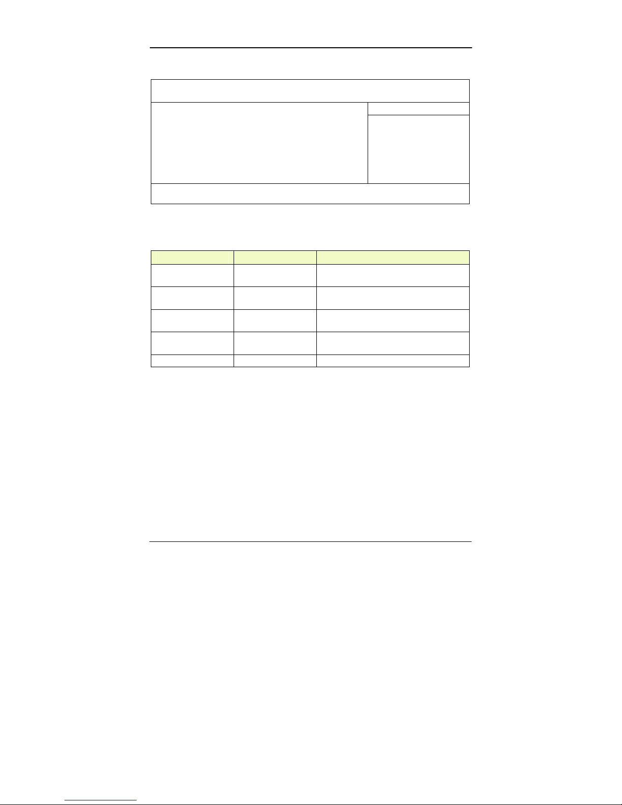
Exit Menu
Phoenix TrustedCore (tm) Setup Utility
Main Advance Security TPM State Boot Exit
Item Specific Help
Exit Saving Changes
Exit Discarding Changes
Load Setup Defaults
Discard Changes
Save Changes
Exit System Setup and
save your changes to
CMOS.
F1 Help ↑↓ Select Item –/+ Change Values F9 Setup Defaults
Esc Exit ↔ Menu Enter Select ► Sub-Menu F10 Save and Exit
Exit Menu Selections
You can make the following selections on the Exit Menu.
Feature Options Description
Exit Saving Changes Exit System Setup and save your
changes to CMOS.
Exit Discarding
Changes
Exit utility without saving Setup data to
CMOS.
Load Setup Defaults Load default values for all SETUP
items.
Discard Changes Load previous values from CMOS for all
SETUP items.
Save Changes Save Setup Data to CMOS
Page 58
Utilities and Drivers
48
UTILITIES AND DRIVERS
Note: Most device drivers are available in Windows. Only when
the default driver does not work properly you need to
install the factory bundled drivers.
The utility CD includes most drivers of the computer’s
installed devices. Consult dealer if any driver is missing.
Re-install drivers or perform “Driver Update” to replace
the Windows default drivers.
Check readme.txt file on utility CD to get the newest
information before starting to install drivers.
Chipset
Windows Driver Installation:
Insert the Driver CD into the DVD-ROM. Click infinst_autol.exe in
the directory of RT8EX\Driver\Chipset\2kXpVista3264 then follow
the prompt to complete installation.
VGA Utility
Display Capability
Resolution & Color LCD RGB LCD + RGB
640x 480x 16-bit color O O O
640x 480x 24-bit color O O O
640x 480x 32-bit color O O O
800x 600x 64K color O O O
800x 600x 24-bit color O O O
800x 600x 32-bit color O O O
1024x 768x 16-bit color O O O
1024x 768x 24-bit color O O O
1280x 1024x 16-bit color X O X
1280x 1024x 24-bit color X O X
1280x 1024x 32-bit color X O X
Page 59

Utilities and Drivers
49
Resolution & Color LCD RGB LCD + RGB
1600x 1200x 16-bit color X O X
1600x 1200x 24-bit color X O X
1600x 1200x 32-bit color X O X
2048x 1536x 16-bit color X O X
2048x 1536x 24-bit color X O X
2048x 1536x 32-bit color X O X
The table lists typical display modes only. The system also supports
standard video modes with lower resolution and color.
Windows Driver Installation:
Insert the Driver CD into the DVD-ROM. Click win2k_xp1429.exe
in the directory of RT8EX\Driver\VGA\Intel_945GM\2kXp32 then
follow prompt to complete driver installation. Windows may
recommend using their driver, but you should confirm to change the
factory bundled driver.
After restart and back to Settings window, choose proper Colors and
Screen Area.
Audio Driver
Windows
Insert the Driver CD into the DVD-ROM. Click WDM_A400.exe in
the directory of RT8EX\Driver\Audio\2kXp_3264 then follow the
prompt to complete installation.
USB 2.0
Windows does not need driver.
Touch Screen Driver
Enter BIOS Setup screen and set COM1 port as “TTL1”. (COM1 has
multiple connectivity, so it’s necessary to setup. The optional COM4
may be configured as touch screen and doesn’t need to configure the
BIOS.) Afterwards, please cancel the prompt of installation wizard
Page 60

Utilities and Drivers
50
to setup the driver from the CD (\RT8EX\Driver\Touchscreen\
DP9000\2kxpVista3264\PM.Universal…v1.0.0.8), and follow the
prompt to complete installation and then restart.
DVD-ROM Driver
In Windows, you don’t need to install drivers, because it is included
in the drivers list.
Only non-Windows OS need the driver
PCMCIA Driver
Windows
The driver is automatically installed under Windows.
Mini PCI 1G AX92200 LAN
Insert the Driver CD into the DVD-ROM. Click Setup.exe in the
directory of E:\AX92200\DRIVER\RTL8110S\windows (612) then
follow the prompt to complete installation.
Mini PCI INT8100 LAN
Windows does not need driver.
Mini PCI-E 1G RTL8111B LAN
Insert the Driver CD into the DVD-ROM. Click setup.exe in the
directory of RT8EX\Driver\PCIe_1G Lan\2kXp3264\RTL8168_
8101E_664 then follow the prompt to complete installation.
Mini PCI-E Intel 3945ABG WLAN
*:
For the driver and software to function correctly on
Windows 2000, the recommendation is to install Service
Pack 4 or later. Ensure that MSI support level 3.1 or
Page 61

Utilities and Drivers
51
above is installed. Use the Windows Installer 3.1 v2 or
greater.
Insert the Driver CD into the DVD-ROM. Click v11.1.0.5_xp32.exe
in the directory of RT8EX\Driver\PCIe_Intel WLAN\2kXp32 then
follow the prompt to complete installation.
Fax/Modem Card Driver
Insert the Driver CD into the DVD-ROM. Click setup.exe in the
directory of RT8EX\Driver\MDC\mdc_w2kxp then follow the
prompt to complete installation.
Bluetooth Driver
Insert the Driver CD into the DVD-ROM. Click setup.exe in the
directory of RT8EX\Driver\BLU-BC4\2kxp\BlueSoleil_(Standard)
then follow the prompt to complete installation.
In “Wireless Manager”, turn on the Bluetooth device.
GPRS/GSM (Siemens MC75) Driver
In “Wireless Manager”, turn on the GSM Phone device.
The screen will display “Found New Hardware Wizard” message.
Then select “Install from a list… (Advanced)”, then select ”Include
this location in the search: RT8EX\Driver\GPRS_GSM Siemens
MC75\USB driver xp2k (MC75)\mc75_08010.usf then follow the
prompt to complete installation.
Wireless Manager
For flight safety and power saving reason, there is a utility to
enable/disable RF devices Wireless LAN/GPRS/GPS/Bluetooth.
Insert the Driver CD into the DVD-ROM. Click setup.exe in the
directory of Utilities\Wireless Manager then follow the prompt to
complete installation.
Page 62

Maintenance/Service
52
MAINTENANCE/SERVICE
Cleaning
ALWAYS turn OFF the power, unplug the power cord and remove
the battery before cleaning.
The exterior of the system and display may be wiped with a clean,
soft, and lint-free cloth. If there is difficulty removing dirt, apply
non-ammonia, non-alcohol based glass cleaner to the cloth and wipe.
An air gun is recommended for cleaning water and dust. For salty
water please clean with fresh water then blow-dry with an air gun.
Be sure not to turn the computer up side down while there is water
being applied.
Troubleshooting
Should the computer fail to function properly, the troubleshooting
steps below may be followed.
- Check AC/vehicle adapter, battery, and the power source.
- Minimize the configuration, i.e. remove extra peripherals and
devices.
- Remove the modules one by one (HDD, DVD-ROM, Battery,
etc.).
- Remove the software suspected.
- Set BIOS fail-safe default.
- Re-install operating system and application software.
RMA Service
If troubleshooting steps are unsuccessful, consult your dealer for
RMA.
Shipping instructions:
1. Remove any personal diskettes, CD's, or other media.
2. Use the original shipping container and packing materials, if
possible.
Page 63

Maintenance/Service
53
3. If the original packing materials are not available, wrap the
equipment with soft material (e.g. PU/PE form) then put the
wrapped equipment into a hard cardboard shipping box.
4. Include a sheet with the following information: (Note: Please
keep a copy of this sheet for your records)
- Name
- Address
- Unit serial number
- Place and date of purchase or the original invoice number
- Date of failure
- A DETAILED Description of the problems you have
encountered
- A list of the hardware/software configuration, if applicable.
5. Clearly mark the outside of the shipping box with the RMA #. If
an RMA # is not present on the shipping box, receiving will be
unable to identify it and it might be returned.
6. Unless prior arrangements have been made, the customer is
responsible for all shipping costs. Unauthorized use of the
company’s shipping accounts is not permitted.
Page 64

Recycled/Recycleable
Printed in Taiwan
P/N: G630800000A
 Loading...