

Page 1

HANDHELD COMPUTER
DB6
USER’S GUIDE
Page 2

Notice
The company reserves the right to revise this publication or to change its
contents without any notice. Information contained herein is for reference only,
and does not constitute a commitment on the part of the manufacturer or any
subsequent vendor. They assume no responsibility or liability for any error or
inaccuracy that may appear in this publication nor are they in anyway
responsible for any loss or damage resulting from the use (or misuse) of this
publication.
Any of the software described in this manual is sold or licensed "as is". Should
the programs prove defective following purchase, the buyer (and not the
manufacturer, its distributor, or its dealer) assumes the entire cost of all
necessary servicing, repair and any incidental or consequential damages
resulting from any software defects.
Copyright © 2010 CReTE Systems Inc.
Page 3

Trademarks
All other brand and product names are trademarks or registered trademarks of
their respective companies.
Page 4

Regulatory Information/ Disclaimers
Installation and use of this computer must be in strict accordance with the
instructions included in the user documentation provided with the product. Any
changes or modifications (including the antennas) made to this device that are
not expressly approved by the manufacturer may void the user’s authority to
operate the equipment.
The manufacturer is not responsible for any radio or television interference
caused by unauthorized modification of this device, or the substitution of the
connecting cables and equipment other than manufacturer specified. It is the
responsibility of the user to correct any interference caused by such
unauthorized modification, substitution or attachment. Manufacturer and its
authorized resellers or distributors will assume no liability for any damage or
violation of government regulations arising from failing to comply with these
guidelines.
Page 5

FCC (Federal Communications Commission) Statement
This equipment has been tested and found to comply with the limits for a Class
B digital device pursuant part 15 of the FCC Rules. These limits are designed
to provide reasonable protection against harmful interference in a residential
installation.
This equipment generates, uses, and radiates radio frequency energy. If not
being installed and used in accordance with the instructions, it may cause
harmful interference to radio communications. However, there is no guarantee
that interference will not occur in a particular installation. If this equipment does
cause harmful interference to radio or television reception, which can be
determined by turning the equipment off and on, the user is encouraged to try
to correct the interference by one or more of the following measures:
Re-orient or relocate the receiving antenna.
Increase the separation between the equipment and receiver.
Connect the equipment into an outlet on a circuit different from that to
which the receiver is connected.
Consult the dealer or an experienced radio/TV technician for help.
This device complies with Part 15 of the FCC Rules. Operation is subject to the
following two conditions:
This device may not cause harmful interference.
This device must accept any interference received, including
interference that may cause undesired operation.
FCC Caution
To assure continued compliance, any changes or modifications
not expressly approved by the party responsible for compliance
could void the user's authority to operate this equipment.
(Example - use only shielded interface cables when connecting to
computer or peripheral devices).
Page 6

CE
Products with the CE Marking comply with both the EMC Directive
(2004/108/EC) and the Low Voltage Directive (2006/95/EC) issued by the
Commission of the European Community.
Compliance with these directives implies conformity to the following European
Norms:
EN55022 CISPR 22 Radio Frequency Interference
EN55024 EN61000-4-2, EN61000-4-3, EN61000-4-4, EN61000-4-5,
EN61000-4-6, EN61000-4-8, EN61000-4-11, EN61000-3-2,
EN61000-3-3,
Generic Immunity Standard
LVD EN 60950 Product Safety, IEC 60950-1: 2005
Page 7

R&TTE (CE) Manual Regulatory Requirement
WLAN - IEEE 802.11a/b/g/n
802.11a/b/g/n Restrictions:
European standards dictate maximum radiated transmit power of 100mW
EIRP and frequency range 2.400-2.4835 GHz. In France, the equipment must
be restricted to the 2.4465-2.4835 GHz frequency range and must be
restricted to indoor use.
Page 8

CE Declaration of Conformity
It is confirmed to comply with the requirements set out in the Council Directive
on the approximation of the laws of the member states relating to
Electromagnetic Compatibility Directive (2004/108/EC), Low-voltage Directive
(2006/95/EC) and the procedures given in R&TTE Directive (99/5/EC).
The equipment was passed, and the equipment test was performed according
to the following European standards:
EN 300 328 V1.7.1:2006
EN 301 893 V1.4.1(2007-07)
EN 301 V1.8.1 2008-04 / EN 301 489-17 V1.3.2 2008-04
EN 50371:2002
EN 60950-1: 2005
UL, TÜ V: AC Adapter (TÜ V includes EN60950 LVD)
Page 9

Environmental Information, Material Safety & Recycling
All materials used in the manufacturing of this equipment are recyclable or
environmentally friendly. Please recycle the packing materials by the local
regulations at the end of the product's service life.
Notice:
The equipment may still contain tiny amount of hazardous substances
for health and environment, though those are below control level.
To avoid spreading such substances into the eco system, and to
minimize the pressure on the natural, you are encouraged to use the
appropriate take-back for reusing or recycling most of the materials in a
safe way after the service life.
The crossed bin symbol indicates proper disposal is required.
For more information on collection, reuse and recycling, please consult
the local or regional waste administration for more information. You can
also contact with the dealer for more information on the environmental
details of the equipment.
The symbol of the crossed out wheeled bin indicates that the
product (electrical and electronic equipment) should not be
placed in municipal waste. Please check local regulations for
disposal of electronic products.
Page 10

TABLE OF CONTENTS
CHAPTER ONE - GETTING STARTED ................................................... 1
UNPACKING ............................................................................................. 1
WORKPLACE ........................................................................................... 2
RUGGEDNESS ......................................................................................... 2
APPEARANCE OVERVIEW .......................................................................... 3
READY FOR USE ...................................................................................... 7
CHAPTER TWO - OPERATING INFORMATION ........................................ 9
START USING YOUR HANDHELD COMPUTER ............................................... 9
STOP USING YOUR HANDHELD COMPUTER ................................................ 9
INSTALLING OPERATION SYSTEM ............................................................. 10
USING INDICATORS AND KEYPAD ............................................................. 11
USING APPLICATION MENU ..................................................................... 13
USING TOUCH SCREEN .......................................................................... 13
USING MICROPHONE .............................................................................. 15
USING FINGERPRINT SENSOR (OPTIONAL) ............................................... 16
OPERATING WIRELESS DEVICES ............................................................. 17
USING CAMERA (OPTIONAL) ................................................................... 21
USING CRADLE (OPTIONAL) .................................................................... 22
CHAPTER THREE - MANAGING POWER ................................ ............. 23
CHARGING BATTERY .............................................................................. 23
CHECKING THE BATTERY LEVEL .............................................................. 23
POWER CONSERVATION ......................................................................... 24
REPLACING BATTERY ............................................................................. 24
POWER SAVING TIPS .............................................................................. 24
SUPPORTING ACPI ................................................................................ 25
AC ADAPTER AND AC POWER CORD SAFETY ........................................... 26
BATTERY PRECAUTIONS ......................................................................... 27
CHAPTER FOUR - BIOS SETUP ....................................................... 28
MAIN MENU ........................................................................................... 28
ADVANCED MENU .................................................................................. 29
BOOT MENU .......................................................................................... 30
Page 11

SECURITY MENU .................................................................................... 31
EXIT MENU ............................................................................................ 32
BIOS SETTING FOR WINDOWS 7 INSTALLATION ........................................ 33
CHAPTER FIVE - DRIVERS AND APPLICATIONS .................................. 36
CHIPSET ............................................................................................... 36
GRAPHIC CONTROLLER .......................................................................... 36
TOUCH SCREEN ..................................................................................... 37
STICKPOINTER ....................................................................................... 37
AUDIO ................................................................ ................................ ... 37
FINGERPRINT SENSOR (OPTIONAL) ......................................................... 37
WIRELESS DEVICES ............................................................................... 38
DEVICE POWER MANAGER ..................................................................... 39
GIGABIT LAN (OPTIONAL) ...................................................................... 39
CRADLE (OPTIONAL) .............................................................................. 40
CHAPTER SIX - SPECIFICATIONS ...................................................... 41
STANDARD SYSTEM UNIT ....................................................................... 41
OPTIONAL DEVICES AND ACCESSORIES ................................................... 43
CHAPTER SEVEN - MAINTENANCE AND SERVICE ............................... 45
CLEANING ............................................................................................. 45
TROUBLESHOOTING ............................................................................... 45
RMA SERVICE ....................................................................................... 46
Page 12

Chapter One - 1
Getting Started
Chapter One - Getting Started
Unpacking
After unpacking, the followings are the standard items along with your
computer. If there is any missing or damaged, please notify the dealer
immediately.
Handheld Computer Unit
AC Adapter
AC Power Cord
Utility DVD
Stylus Pen
Quick Guide
Page 13

Chapter One - 2
Getting Started
Workplace
A clean and moisture-free environment is preferred. Make room for air
circulation. Remember to avoid areas from:
Sudden or extreme changes in temperature.
Extreme heat.
Strong electromagnetic fields (near television set, motor rotation area,
etc.).
Dust or high humidity.
If it is necessary to work in a hostile environment, please regularly maintain
your computer by cleaning dust, water, and etc. to keep it in an optimal
condition.
Environmental Ratings-
Operating Temperature: 0 ~ +40 ºC (DB6-I)/ -20 ~ +50 ºC (DB6-M)
Operating Altitude: 0 ~ 4,572 meters
Operating Humidity: Up to 95%
Ruggedness
The computer is designed with rugged features such as vibration, shock, dust,
and rain/ water protection. However, it is still necessary to provide appropriate
protection while operating in harsh environments.
Since the handheld computer is passed MIL-STD-810G for the temperature,
vibration, shock, humidity and salt fog tests, and IP55 (I Model) or IP65 (M
model) for dust and water resistant tests, the handheld computer is therefore a
fully-rugged one.
Page 14
Chapter One - 3
Getting Started
Appearance Overview
Before starting to use your handheld computer, we suggest you to have a
quick glance at it to know the external components well.
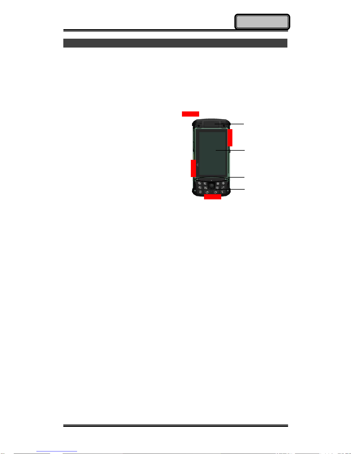
Front
1. Embedded Antennas:
Embedded antennas for wireless
application
2. LCD:
For displaying the output of the handheld
computer
3. LED Indicators:
For indicating status by different colors
and lighting methods.
4. Keypad:
For quick operation
1
2 3 4
Side A
Side B
Side C
Side D
Page 15
Chapter One - 4
Getting Started
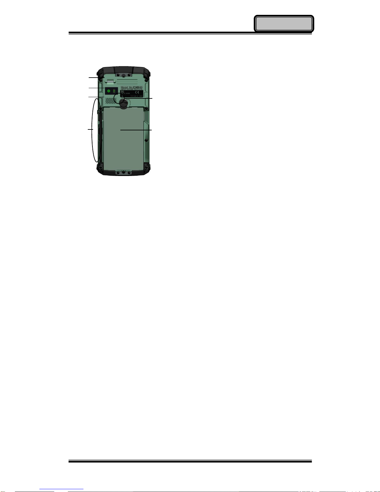
Rear
1. Fingerprint Reader (Optional):
Scanning users’ fingerprints for
security
2. 2M AF Camera (Optional):
Capturing images and recording
videos
3. Speaker:
Internal speaker
4. Battery Lock:
Locating the battery correctly and
locking with it.
5. Stylus Pen:
Tool pen for using touch screen
6. Battery:
Swappable Li-Ion Battery
1
2 3 5 6 4
Page 16
Chapter One - 5
Getting Started
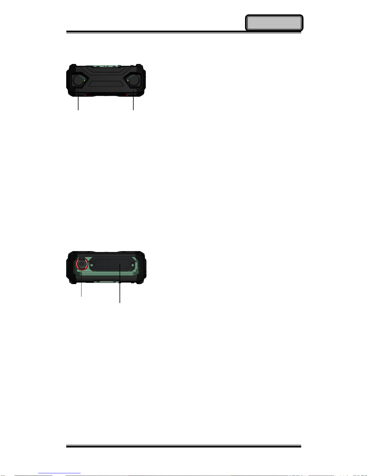
Side A
Location 1 & 2 Standard:
No Function
Location 1 & 2 Optional:
(Select 2 out of 7)
a. Sealed USB
b. Sealed Gigabit LAN (Trade-off:
WLAN)
c. Sealed Audio
d. GPS SMA Antenna
e. Wi-Fi SMA Antenna
f. HSDPA/ UMTS SMA Antenna
g. Bluetooth SMA Antenna
Side B
DC Power Jack:
For external power supply and power
charging
Location 5 Standard:
No Function
Location 5 Optional:
Expansion POGO Connector
Signals consisted:
a. USB x 1
b. COM1 (RS232)
c. RGB (Trade-off: Cradle RGB)
d. Gigabit LAN
e. DC In
DC Power Jack
Location 5
Location 1 Location 2
Page 17
Chapter One - 6
Getting Started
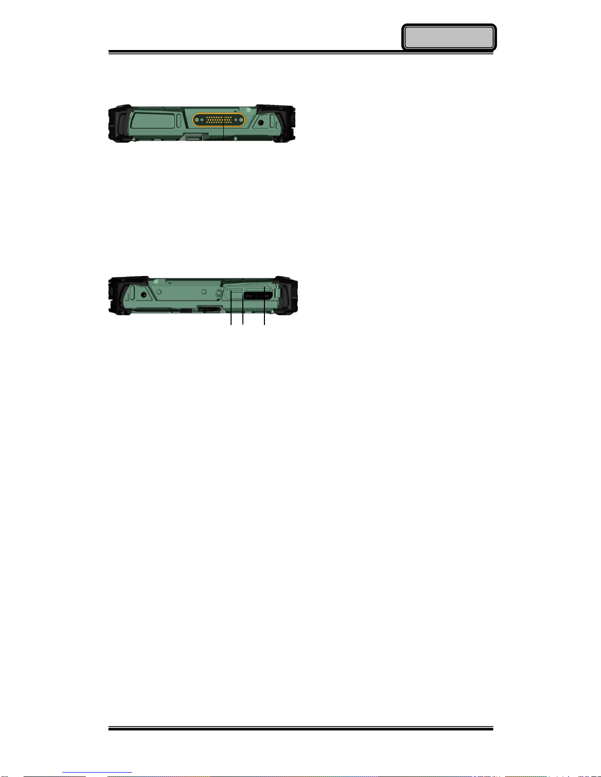
Side C
Location 4-
Cradle POGO Connector:
For connecting with the
optional cradle.
Side D
Standard I/O Ports:
Location 3-
Standard I/O Ports:
1. SIM Card Slot
For Inserting SIM card
2. USB 2.0 Port (Host)
Connecting with USB
Devices
3. SD Card Slot
For reading SD card
1
2
3
Location 4
Page 18
Chapter One - 7
Getting Started
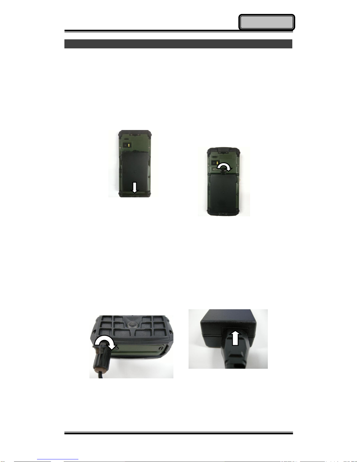
Ready for Use
After taking a quick look at your handheld computer, the following illustrations
will get you ready for using it.
Mounting the Battery
1.
Mount the battery into the
battery bay.
2. Use a suitable-size coin to
lock.
Connecting with AC Adapter
1. Insert the DC Jack to the end
and lock the connector well
clockwise.
2. Plug the AC cord to the AC
adapter.
3. Plug the AC cord to a right electrical outlet.
Page 19
Chapter One - 8
Getting Started
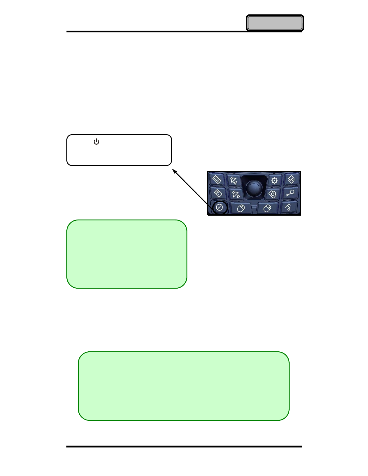
Turning ON the Power
1. Make sure the battery is mounted or connect all power cords well for the
stable power supply.
2. Now, you are able to turn ON the power of your handheld computer by
pressing “Power Button”.
Turning OFF the Power
Directly click “Shut down” from your OS to turn OFF the power of your
handheld computer.
Note:
The power is able to be ON
without any battery mounted
once all the power cords are
connected well.
Please see more information in
“Operating Information”.
Note:
The above-mentioned description is a standard way to turn
OFF the power. Directly turn OFF the power by pressing
“Power Button” will cause data lose and is not suggested.
There are still other ways to stop your handheld computer
from operating, see more information in “Operating
Information”.
Press on the keypad to turn
on the power of your handheld
computer.
Page 20

Chapter Two - 9
Operating Information
Chapter Two - Operating Information
Start Using Your Handheld Computer
Always turning on your handheld computer by using the power button, this is a
standard operating procedure to start using your handheld computer. After
turning on the power of your handheld computer, it will start with the operating
system (OS) such as Windows XP.
Boot up
When turning on the power, your handheld computer will start loading the OS
into the system memory. This start-up procedure is called “boot up”.
Power on Self-Test (POST)
Each time when your handheld computer is turned on, BIOS will automatically
perform a self-test of CPU, memory, hardware devices, and so on.
Stop Using Your Handheld Computer
Each time when you finish working with your handheld computer, there are
several ways to stop your handheld computer from operating.
Shut down
Directly click “Shut down” from your OS such as Windows XP to turn OFF the
power of your handheld computer. Before shutting down, please always
remember to save the unfinished works and close the application for
preventing from any possible data loss or HDD damage.
“Shut down” will totally turn OFF the power of your handheld computer. If you
want to start your handheld computer again, you need to press the power
button.
Page 21

Chapter Two - 10
Operating Information
Standby
Under “Standby” mode, the system will temporarily save your work into RAM. If
you want to start your handheld computer again, all you need to press any key.
You are able to do enter “Sleep” mode by directly clicking “Start” => “Shut
down” => “Standby” from your OS such as Windows XP. Or, you can do the
“Sleep” Mode settings in your OS.
Hibernate
Under “Hibernate” mode, the system will save your work into HDD. If you want
to start your handheld computer again, you need to press the power button.
You are able to do enter “Hibernate” mode by setting from your OS such as
Windows XP.
Installing Operation System
Your handheld computer is designed to operate with Microsoft Windows XP
and Windows 7 32-bit operations systems. Please connect your handheld
computer with a suitable USB-interface ODD to start the installation.
Note:
Since a USB hub may be required during installation to connect
with an external USB-interface ODD and Keyboard, the power
supply from System USB port may not be enough. Please
connect your USB hub with extra power supply to complete the
installation.
Page 22
Chapter Two - 11
Operating Information
Using Indicators and Keypad
Your handheld computer is designed with a keypad for easy and quick
operation. Also, each LED indicator shows different meanings.
Here are the descriptions for each button and LED indicator to help you use
well with your handheld computer.
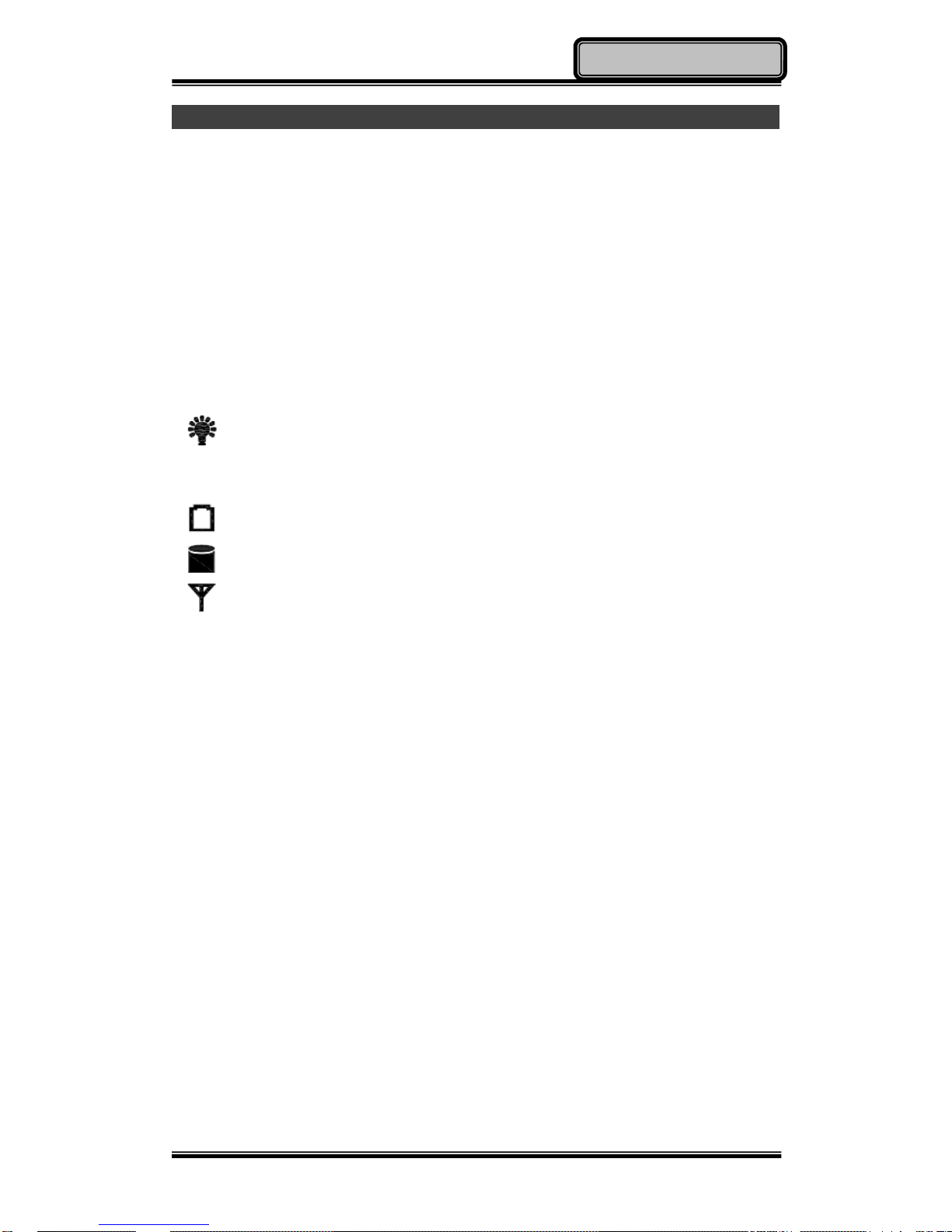
Indicators
Power Indicator: Green (Power); Flashing Red (S3: Standby);
Consistent Green + Flashing Red (Battery power is lower than 15%
under S3 mode)
Charger Indicator: Orange
SSD Indicator: Green (SSD); Red (Input Lock)
Wireless Devices Indicator: Blue
Page 23
Chapter Two - 12
Operating Information
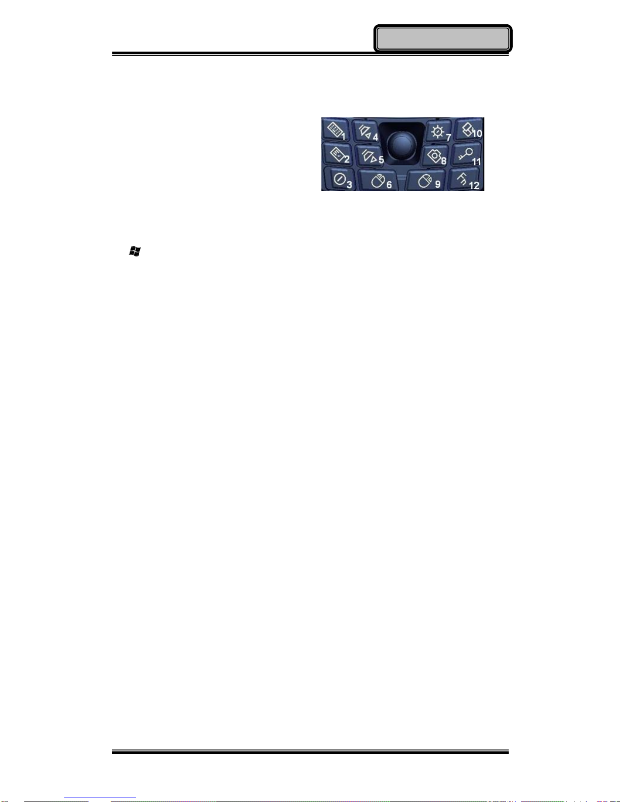
Keypad Hotkey
Before using the keypad functions,
please install the Device Power
Manager application to activate the
hotkeys.
1st Layer:
1. “ ”+ “U”
2. Application Menu
3. Power On/Off
4. Volume Up
5. Volume Down
6. Mouse’s Left Button
7. Invisible Mode On/Off
8. Camera
9. Mouse’s Right Button
10. Screen Rotation
11. Login
12. Function Key
2nd Layer:
a. Fn + Invisible Mode On/Off =
Keypad Backlight On/Off
b. Fn + Volume Up/ Down =
LCD Brightness Up/ Down
c. Fn + Key 1 = Input Lock
d. Fn + Application Menu = Enter
Note: Text Input is a quick access to common tools such as Magnifier and
On-Screen Keyboard.
Page 24
Chapter Two - 13
Operating Information
Using Application Menu
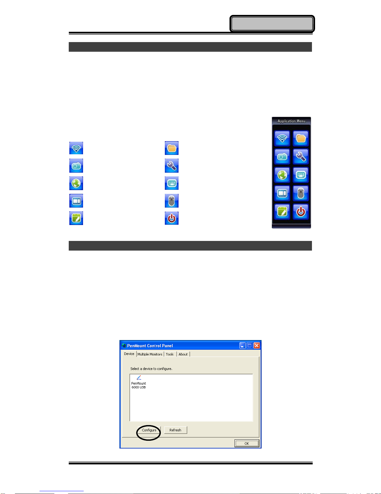
Application Menu is a hotkey to help you directly access to the functions you
often use. Device Power Manger includes the driver of the keypad hotkeys.
Do remember to install this application before activating the keypad hotkeys.
Please see the followings for the illustrations:
Device Power Manager
My Documents
Camera Application
Control Panel
Internet Explorer
Keyboard
Media Player
Mouse Left Button
Notepad
Standby
Using Touch Screen
Your handheld computer is equipped with a high sensitive touch panel allowing
you to navigate on the touch screen easily without using any other devices
such as external keyboard or mouse. Before using touch screen, please follow
the illustrations as below to make your stylus pen for a more precise
positioning:
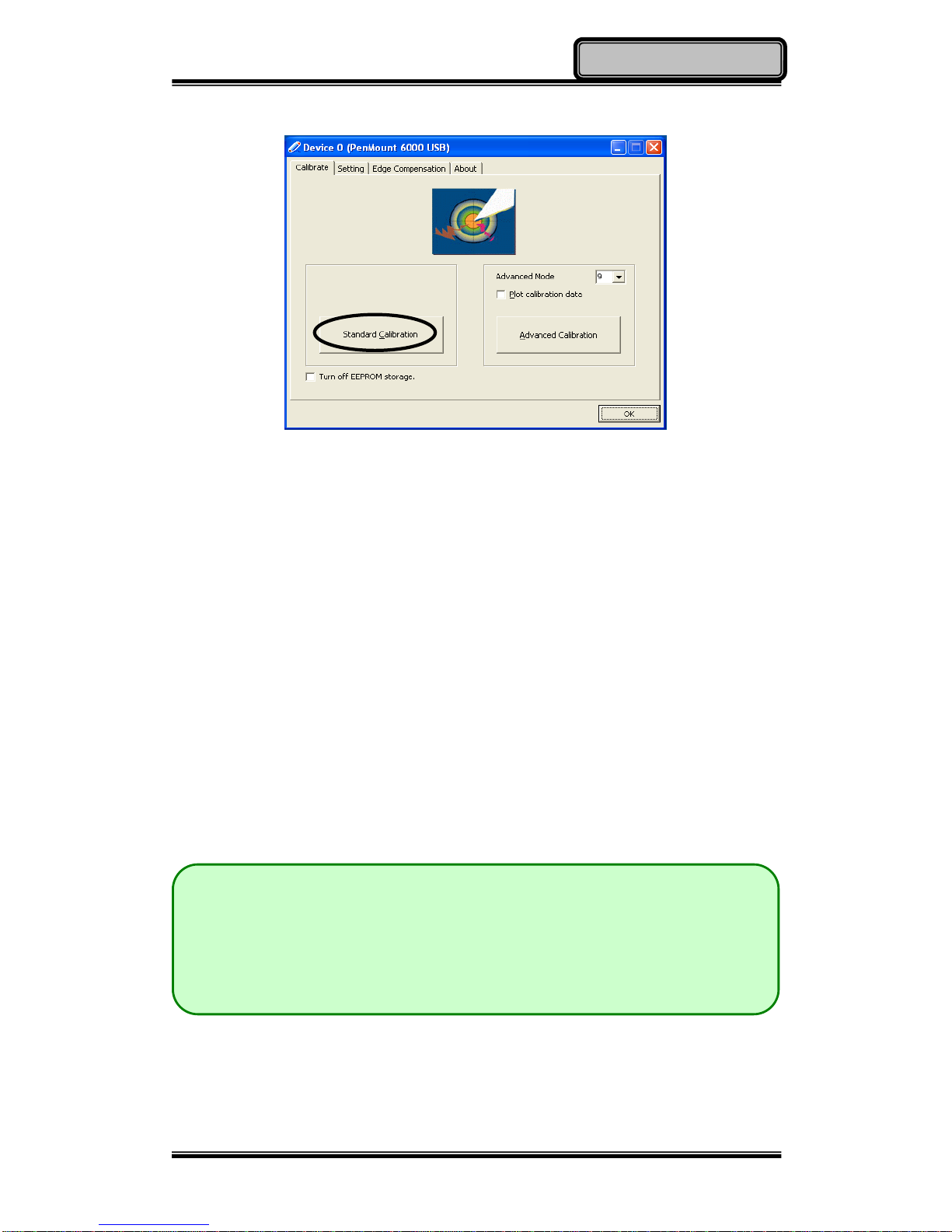
1. Click “Configure” to start.
Page 25
Chapter Two - 14
Operating Information
2. Use “Standard Calibration” and follow the instructions.
A stylus pen is provided for you to use well with the touch screen. Here are
some operating tips to help you use the touch screen well with a stylus pen.
Single Click: Tapping the touch screen with a stylus pen gently
Double Click: Tapping the touch screen quickly twice with a stylus pen
Drag and Drop: Clicking and holding the object with a stylus pen slightly
and moving to the destination you want (Drag). Leave
the stylus pen from the touch screen once you finish
dragging (Drop).
Right Click: Pressing harder on one point of the touch screen and
holding for 2~3 seconds. This is the same as using the
right click of a mouse.
Note:
Touch harder with your stylus pen on the icons around the edges. Or,
press Hotkey “Text Input” for accessing to common tools and use the
magnifier to magnify the edge icons for an easier click.
Under the direct sunlight for a longer time, the touch screen could
heat up over 70℃ of a specified maximum temperature.
Page 26
Chapter Two - 15
Operating Information
Using Microphone
It is able for you to record sounds and voices through your handheld computer.
Please follow the instruction listed as below to start.
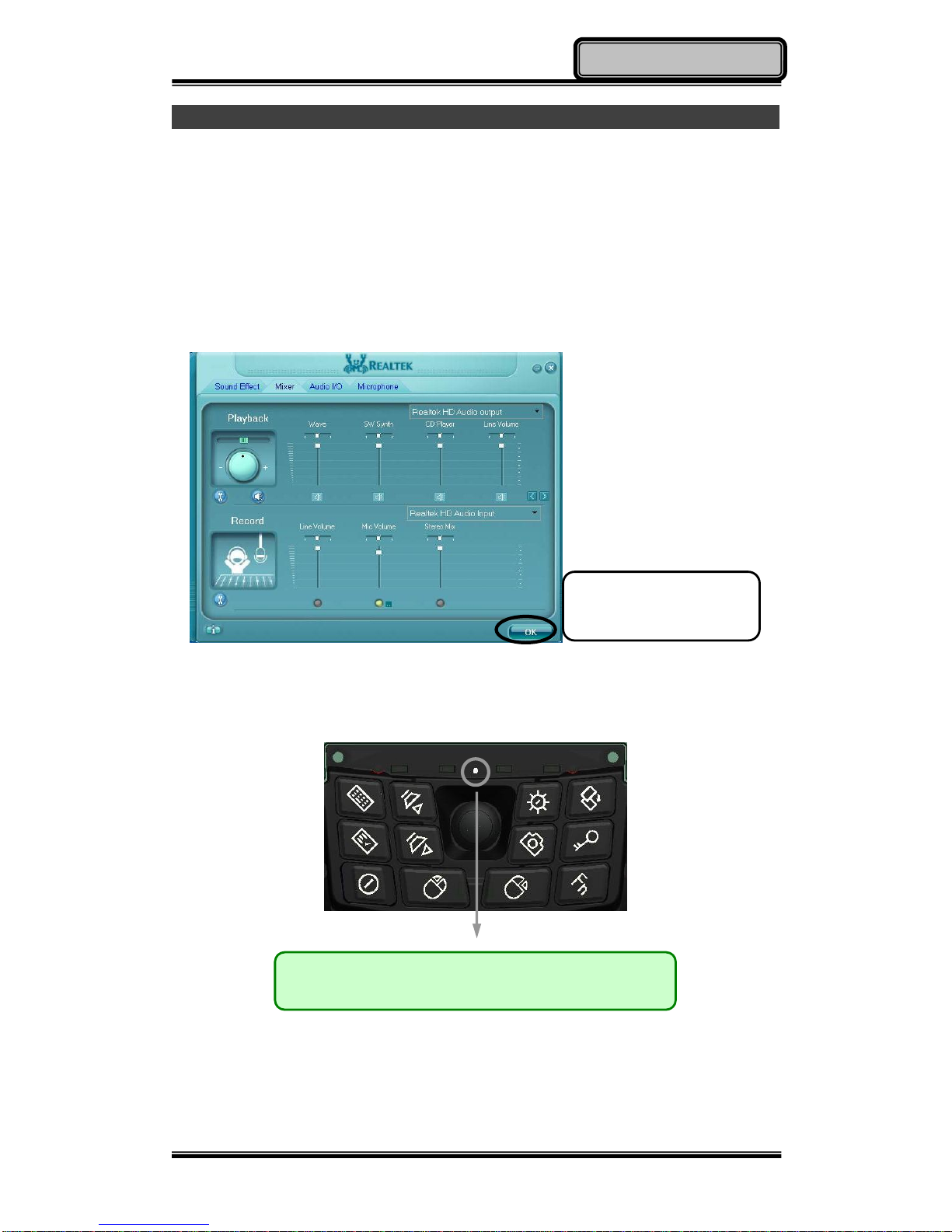
1. Before recording, be sure to enter into Realtek HD Audio Manager, and do
the same setting as the picture.
2. Please make the sound sources close to the microphone for having better
quality.
Start recording with your recorder such as Sound Recorder in Windows XP.
(Start => Programs => Accessories => Entertainment => Sound Recorder)
Set the microphone as
your recording tool and
then click OK to confirm.
Note:
The microphone is located in the middle.
Page 27
Chapter Two - 16
Operating Information
Using Fingerprint Sensor (Optional)
Your handheld computer provides a fingerprint sensor for user to strengthen
the authentication and security. The followings are steps to set your fingerprint
through it.
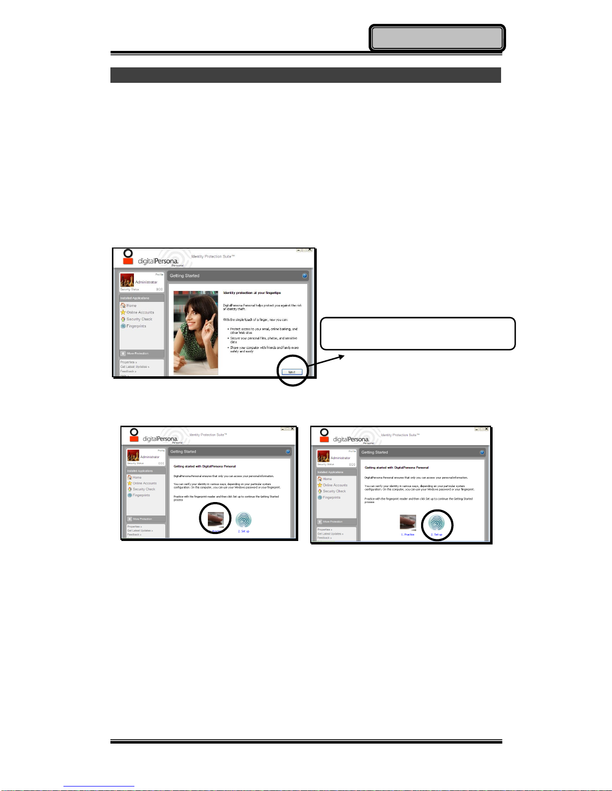
1. Read from the utility DVD to install “DigitalPersona” and the driver.
2. Open “DigitalPersona”
3. Click “Next” to start the setting.
4. You are able to Practice first.
5. Or, directly set up.
After Opening “DigitalPersona Personal”,
please click “Next” to start the settings.
Page 28
Chapter Two - 17
Operating Information
Operating Wireless Devices
For a new designed handheld computer with strong communication features,
you are able to turn ON/OFF your Wireless Devices through the proprietary
application - “Device Power Manager”.
Bluetooth
Bluetooth is a standard wireless device along with your handheld computer. A
Class 2, Bluetooth® v2.1 + EDR system is backward compatible with
v1.1/1.2/2.0 devices. It will support your handheld computer a short-range
wireless communication to connect with other devices.
To activate your Bluetooth function, please follow the illustrations as below.
1. Driver & Application Installation
a. Install the Bluetooth driver first
Read from the Utility DVD and find the directory in readme to finish
installation.
b. Then, install the Device Power Manager application
Read from the Utility DVD and find the directory in
readme to finish installation.
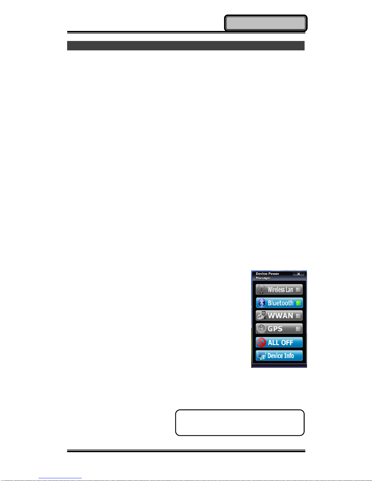
2. Launch the Device Power Manager
After launching the utility, please click “Bluetooth” for
enabling the Bluetooth function (click again for
disabling the Bluetooth function).
Once the Bluetooth function starts up, the Wireless LED indicator will turn on in
blue and the Bluetooth icon will show up in the OS accordingly.
Click “Bluetooth” for enabling the Bluetooth
function (click again for disabling the Bluetooth
function).
Page 29
Chapter Two - 18
Operating Information
Wireless LAN (Optional)
Wireless LAN card is an optional device for your handheld computer. For
supporting IEEE 802.11 a/b/g/n, wireless LAN card and embedded antenna
will be pre-installed in your handheld computer to access the internet
wirelessly.
To activate your Wireless LAN function, please follow the illustrations as below.
1. Driver & Application Installation
a. Install the Chipset Driver first:
Read from the Utility DVD and find the directory in readme to finish
installation.
b. Then, install the Device Power Manager application:
Read from the Utility DVD and find the directory in readme to finish
installation.
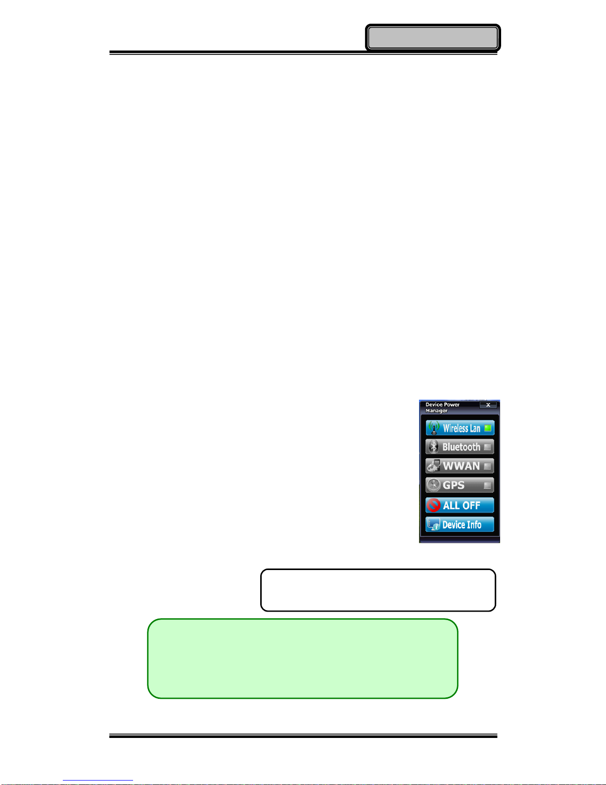
2. Launch the Device Power Manager
After launching the utility, please click “Wireless LAN” for
enabling the Wireless LAN function (click again for
disabling the Wireless LAN function).
Once the Wireless LAN function starts up, the Wireless
Device LED indicator will turn on in blue and the Wireless
LAN icon will show “connected” in the OS accordingly.
Note:
Since this handheld computer does not support cell
phone function, but users are able to make phone calls
through VOIP when equipped with Wireless LAN
function.
Click “Wireless LAN” for enabling the Wireless LAN
function (click again for disabling the Wireless LAN
function).
Page 30
Chapter Two - 19
Operating Information
WWAN (Optional)
WWAN is an optional module for your handheld computer. With pre-installed
embedded antenna and the optional 3.5G WWAN module, your handheld
computer will be able to do the telecommunication after installing with a 3.5G
SIM card.
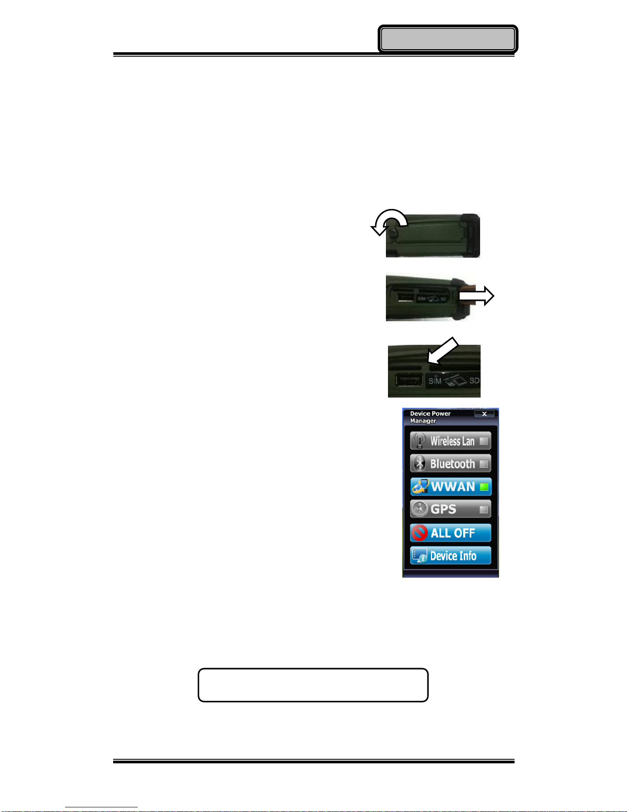
1. Insert the SIM card
a. Turn OFF your handheld computer.
b. Open the lock cover.
c. Pull up the lock cover.
d. Put the SIM card into the SIM card slot.
e. Lock the cover.
2. Driver & Application Installation
a. Install the WWAN driver first:
Read from the Utility DVD and find the directory in
readme to finish installation.
b. Install the Device Power Manager application:
Read from the Utility DVD and find the directory in
readme to finish installation.
3. Launch the Device Power Manager
After launching the application, please click “WWAN” for enabling the
WWAN function (click again for disabling the WWAN function). Once the
WWAN function starts up, the Wireless Device LED indicator will turn on in
blue.
Click “WWAN” for enabling the WWAN function
(click again for disabling the WWAN function).
Page 31
Chapter Two - 20
Operating Information
GPS (Optional)
GPS is an optional module for your handheld computer. This GPS module
supports GPS and Galileo systems
Driver & Application Installation:
1. Install the Device Power Manager application:
Read from the Utility DVD and find the directory in readme to finish
installation.
2. Install the GPS driver:
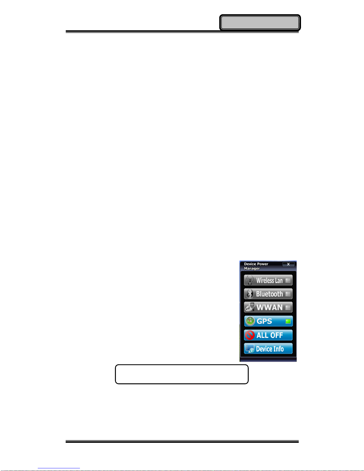
First, please enter into Device Power Manager to turn GPS ON. The
screen will display "Found New Hardware Wizard". Then select "No, not
this time" => "Install from a list…. (Advanced)" => "Include this location in
the search: DB6\Drivers\XP\GPS LEA-5H\Windows WinXP\Driver", then
follow the prompt to complete installation.
a. GPS (Driver): Read from the Utility DVD and find the directory in
readme to finish installation.
b. GPS (Application): Read from the Utility DVD
and find the directory in readme to finish
installation.
Click “GPS” for enabling the GPS function (click
again for disabling the GPS function).
Page 32

Chapter Two - 21
Operating Information
Using Camera (Optional)
Your handheld computer provides an optional 2 million-pixel CMOS camera for
you to capture images at any time. Also, it supports video recording function for
more application. You are able to press the camera button or application menu
button to enter into the camera window as below.
Taking Pictures
Click in the camera window to take pictures. Or, you can press the
camera button again to capture the images.
After taking pictures, your pictures will automatically be saved in C:\Documents
and Settings\Administrator\My Document\My Pictures.
Recording Video
Click in the camera window to recording video. To stop recording, please
click . While recording, you can also adjust the volume.
After recording video, your video files will automatically be saved in
C:\Documents and Settings\Administrator\My Document\My Video.
Page 33

Chapter Two - 22
Operating Information
Other Functions
Video Format Properties: Advanced video format adjusting
Image Properties: Advanced image settings and camera control
Volume Level: Adjust video recording volume
Flash LED Settings: Advanced flash LED settings
Exit: Exit the camera window/ function
Using Cradle (Optional)
Cradle is designed for docking, ports extending and charging. Before using
Cradle, please install the related drivers first for activating cradle’s functions.
Mounting with Cradle
1. Dock cradle either power is ON or
OFF. (Recommend OFF).
2. There are both arrows on the
handheld computer and cradle.
Please follow the arrows to connect
the cradle connectors well.
3. Firmly push the handheld computer
down to engage the docking
connector.
4. Turn rotary latch to fix the handheld computer.
Note:
The module is designed for camera use only.
Page 34

Chapter Three - 23
Managing Power
Chapter Three - Managing Power
Charging Battery
An AC adapter, an AC power cord and a battery are required during battery
charging. These are standard accessories for your handheld computer. Do
always use the AC adapter, the AC power cord and the battery designed for
your handheld computer.
After unpacking your handheld computer, the first thing you need to do is
starting charging battery for the further use. Please connect your AC power
cord and AC adapter well with the plug and mount your battery well before
starting charging. We suggest you to charge the battery for about 8 hours at
the very beginning to give a full charge for your battery.
When the battery is nearly exhausted, please save and close the files you are
currently working on, and plug in the AC adapter to recharge the battery or
swap with a charged battery.
Checking the Battery Level
After a full charge of your battery, you are now able to check your battery level
by using the battery meter function of your OS. The battery icons which show
the conditions of the battery or where the power source comes from may be
different depending on the OS you install.
When the battery is nearly exhausted, the OS will show a warning icon. Also,
the Power Indicator LED will flash green when the battery level is under 15%.
Note:
To ensure system stability, please connect your computer to an
external power source when operating at -20 °C ambient
temperature.
Page 35
Chapter Three - 24
Managing Power
Power Conservation
This computer consumes much less power than conventional computers.
However, power consumption may be reduced by configuring the Power
Management Setup properly.
It is recommended the power saving functions to be enabled even when not
running on battery power. Power Management will not degrade performance
while saving power.
Replacing Battery
When the battery is nearly exhausted, there are two ways to keep your
handheld computer working. Connect the AC adapter and the power cord
designed for this handheld computer to start charging is one method; directly
replace a charged battery designed for this handheld computer may be the
other one.
Power Saving Tips
Turn OFF the LCD backlight when not using the handheld computer.
Lower the intensity of the LCD backlight.
Use well with Shut down, Standby and Hibernation.
Use well with the power management settings in your OS.
Note:
Always remember to turn OFF the power before replacing the
battery.
You can change the battery in 30 seconds under standby
mode; otherwise, it may cause the data loss or malfunction of
your handheld computer.
Page 36

Chapter Three - 25
Managing Power
Supporting ACPI
Your handheld computer supports ACPI (Advanced Configuration and Power
Interface) for power management. With ACPI and an ACPI-compliant
operating system such as Windows, the feature will allow you to reduce the
power consumption for energy saving. By supporting ACPI, the AC adapter
LED and the Power indicator LED will show in different ways. The followings
are the detailed description.
Standby:
Power LED indicator is ON; Other LED indicators are OFF
Under Hibernation:
All LED indicators are OFF
Shutdown:
All LED indicators are OFF
Page 37

Chapter Three - 26
Managing Power
AC Adapter and AC Power Cord Safety
There are specific power requirements for your handheld computer:
Only use an approved AC adapter designed for this computer.
There is a 3-prong grounded plug of the AC adapter. The third prong is an
important for safety. Do not neglect the importance for it. If you are not
able to access a compatible outlet, installing one by a qualified electrician
is necessary.
When unplugging the AC power cord, please be sure to disconnect it from
the plug head but from its wire.
Make sure the socket and any other extension cord you use can support
the total current load of all the connected devices.
Before cleaning the computer, make sure it is disconnected from any
external power supplies.
Page 38
Chapter Three - 27
Managing Power
Battery Precautions
Only use the batteries designed for this computer. The wrong battery may
cause explosion, leakage or damage to the computer.
Do not remove the battery from the computer while it is powered on.
Do not continuously use a battery that has been dropped, or that appears
damaged (e.g. bent or twisted) in any way. Even if the computer is able to
continuously work with a damaged battery, the circuit damage may occur
and possibly cause fire.
Always use the charger designed for this handheld computer to recharge
the battery. Incorrect recharging may make the battery explode.
Do not try to repair a battery by yourself. Refer to any battery repair or
replacement, please contact with to your service representative.
Please dispose of a damaged battery promptly and carefully. Explosion or
leakage may occur, if the battery is exposed to fire, improperly handled or
discarded.
Warning
Before any upgrade procedures, make sure the power is turned
off, and all the cables are disconnected (including telephone
lines). Also, it is advisable to remove your battery in prevent from
turning the computer on accidentally.
Battery Disposal & Caution
The product that you have purchased contains a rechargeable
battery. The battery is recyclable. At the end of its service life,
under various state and local laws, it may be illegal to dispose of
this battery into the municipal waste stream. Check with your
local solid waste officials for details in your area for recycling
options or proper disposal. Danger of explosion may possibly
occur, if the battery is incorrectly replaced. Replace only with the
same or the equivalent battery recommended by the
manufacturer. Discard the used battery according to the
manufacturer’s instructions.
Page 39

Chapter Four - 28
Page 40
Chapter Four - 29
BIOS Setup
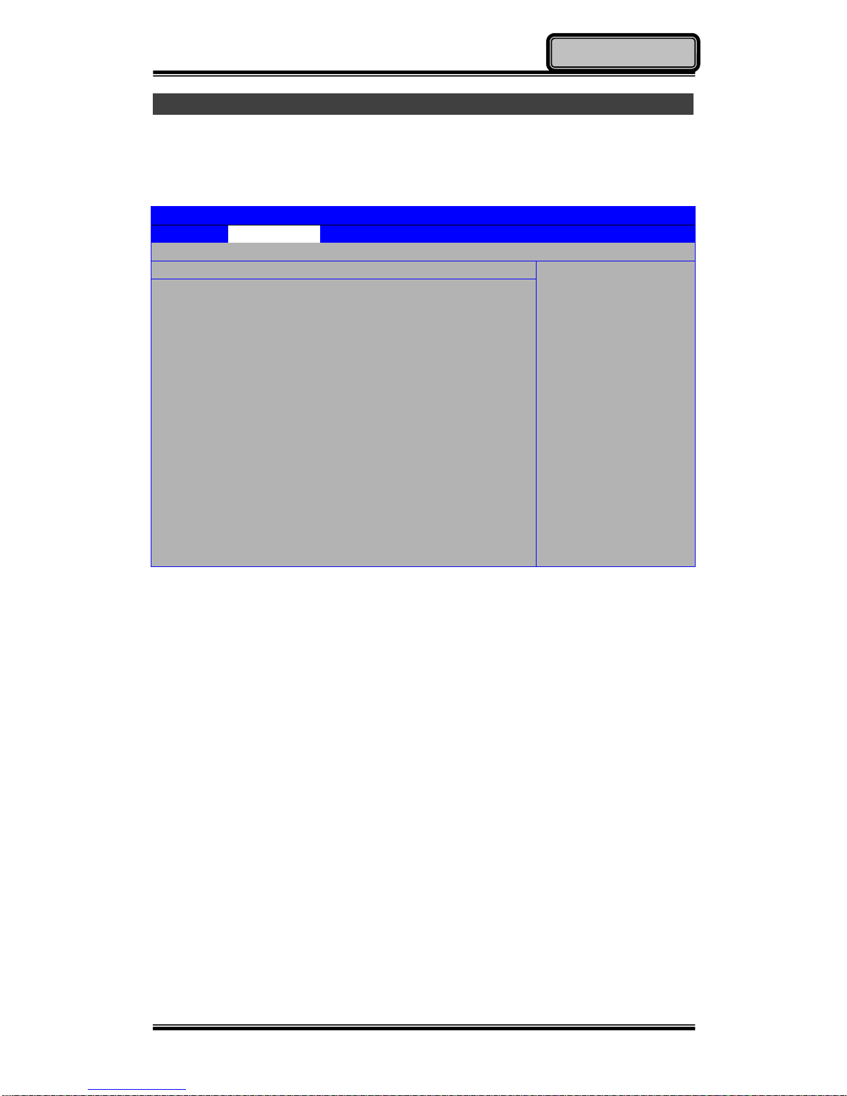
Advanced Menu
In Advanced Menu, you are able to do the advanced settings.
BIOS SETUP UTILITY
Main
Advanced
Boot
Security
Exit
Advanced Settings
← Select Screen
↑↓ Select Item
Enter Go to Sub
Screen
F1 General Help
F10 Save and
Exit
Esc Exit
Warning: Setting wrong values in below sections
may cause system to malfunction.
► DEVICES Control
Thermal cooling trip point [79C]
Critical trip point [103C]
Installed O/S [Win/ XP DOS]
Page 41
Chapter Four - 30
BIOS Setup
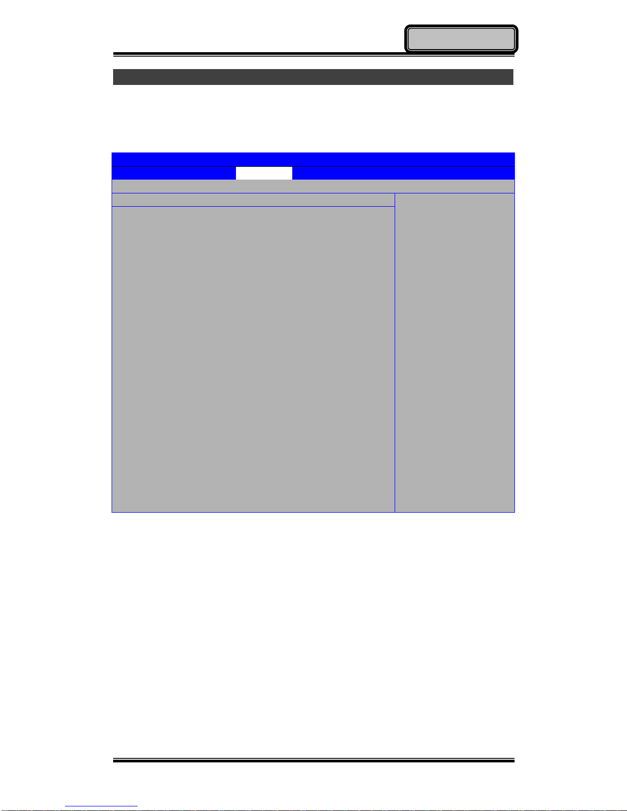
Boot Menu
In Boot Menu, you are able to do the boot settings.
BIOS SETUP UTILITY
Main
Advanced
Boot
Security
Exit
Boot Settings
Specifies the boot
sequence from the
available devices.
A device enclosed in
parenthesis has been
disabled in the
corresponding type
menu.
← Select Screen
↑↓ Select Item
Enter Go to Sub
Screen
Tab Select Field
F1 General Help
F10 Save and
Exit
Esc Exit
1st Boot Device [USB]
2nd Boot Device [SATA: PM- PATA SSD]
3rd Boot Device [CD/DVD]
4th Boot Device [Removable Dev.]
Page 42
Chapter Four - 31
BIOS Setup
Security Menu
In Security Menu, you are able to do the security settings.
BIOS SETUP UTILITY
Main
Advanced
Boot
Security
Exit
Security Settings
Install or Change the
password.
← Select Screen
↑↓ Select Item
Enter Change
F1 General Help
F10 Save and Exit
Esc Exit
Supervisor Password :Not Installed
User Password :Not Installed
Change Supervisor Password
Change User Password
Page 43
Chapter Four - 32
BIOS Setup
Exit Menu
In Exit Menu, you are able to do the exit option settings.
BIOS SETUP UTILITY
Main
Advanced
Boot
Security
Exit
Exit Options
Exit system setup after
saving the changes.
F10 key can be used for
this operation.
← Select Screen
↑↓ Select Item
Enter Go to Sub Screen
F1 General Help
F10 Save and Exit
Esc Exit
Save Changes and Exit
Discard Changes and Exit
Discard Changes
Load Optimal Defaults
Load Failsafe Defaults
Page 44
Chapter Four - 33
BIOS Setup
BIOS Setting for Windows 7 Installation
BIOS SETUP UTILITY
Main
Advanced
Boot
Security
Exit
Exit Options
Load Optimal Default
values for all the setup
questions.
F9 key can be used for
this operation.
← Select Screen
↑↓ Select Item
Enter Go to Sub Screen
F1 General Help
F10 Save and Exit
Esc Exit
Save Changes and Exit
Discard Changes and Exit
Discard Changes
Load Optimal Defaults
Load Failsafe Defaults
Page 45
Chapter Four - 34
BIOS Setup
BIOS SETUP UTILITY
Main
Advanced
Boot
Security
Exit
Advanced Settings
Options
Win XP/ DOS
Windows 7
Linux
← Select Screen
↑↓ Select Item
Enter Go to Sub
Screen
F1 General Help
F10 Save and
Exit
Esc Exit
Warning: Setting wrong values in below sections
may cause system to
malfunction.
► DEVICES Control
Thermal cooling trip point [79C]
Critical trip point [103C]
Installed O/S [Windows 7]
Page 46
Chapter Four - 35
BIOS Setup
BIOS SETUP UTILITY
Main
Advanced
Boot
Security
Exit
Exit Options
Exit system setup
after saving the
changes.
F10 key can be used
for this operation.
← Select Screen
↑↓ Select Item
Enter Go to Sub
Screen
F1 General Help
F10 Save and
Exit
Esc Exit
Save Changes and Exit
Discard Changes and Exit
Discard Changes
Load Optimal Defaults
Load Failsafe Defaults
Page 47
Chapter Five - 36
Drivers and Applications
Chapter Five - Drivers and Applications
The Utility DVD includes all the drivers for the installed devices in your
handheld computer. Please consult the dealer if there is any driver missing.
Also, through Device Manager in Windows, you are able to perform “Driver
Update” or check if there are still drivers for the devices needed to be installed.
Check readme.txt file on Utility DVD to get the newest information before
starting to install drivers.
Chipset
Read from the Utility DVD and find the directory in readme to finish installation.
Graphic Controller
Your handheld computer supports Intel® GMA500 giving you a flexible,
programmable architecture that supports high-definition video decode and
image processing. Please follow the installation as below to use well with
Intel® GMA500.
Read from the Utility DVD and find the directory in readme to finish installation.
Note:
Please install the chipset driver first.
If there is any “reboot” showed while installing. Please
follow the instructions to reboot first and then install
next driver.
Page 48

Chapter Five - 37
Drivers and Applications
Touch Screen
Your handheld computer is equipped with a high sensitive touch panel. Please
follow the installation as below to start using your touch screen.
Read from the Utility DVD and find the directory in readme to finish installation.
Stickpointer
Stickpointer helps you to navigate your cursor on the screen. Please follow the
installation as below to start using your stickpointer.
Read from the Utility DVD and find the directory in readme to finish installation.
Audio
Your handheld computer provides a high-quality audio sound effect for user to
enjoy better sound quality. To activate this function, please follow the
installation as below.
Read from the Utility DVD and find the directory in readme to finish installation.
Fingerprint Sensor (Optional)
Your handheld computer provides a fingerprint sensor for user to strengthen
the authentication and security. To activate this function, please follow the
installation as below.
Read from the Utility DVD and find the directory in readme to finish installation.
Page 49
Chapter Five - 38
Drivers and Applications
Wireless Devices
Your handheld computer supports wireless communication. Bluetooth is a
standard equipped wireless device. If your model supports optional wireless
connection, please see the followings to install the drivers and applications.
Bluetooth
Read from the Utility DVD and find the directory in readme to finish installation.
WLAN (Optional)
Depending on the model you choose; if your handheld computer is equipped
with a WLAN model, please follow the installation as below to connect your
handheld computer with the internet wirelessly.
Read from the Utility DVD and find the directory in readme to finish installation.
WWAN (Optional)
Depending on the model you choose; with pre-installed embedded antenna
and the optional 3.5G WWAN module, DB6 will be able to do the
telecommunication after installing with a 3.5G SIM card. Please follow the
installation as below.
Read from the Utility DVD and find the directory in readme to finish installation.
Note:
Please see DB6 Technical Reference for more WWAN
installation information.
Page 50
Chapter Five - 39
Drivers and Applications
GPS (Optional)
Depending on the model you choose; being able to activate the function,
please follow the installation as below.
GPS (Driver): Read from the Utility DVD and find the directory in readme to
finish installation.
GPS (Application): Read from the Utility DVD and find the directory in readme
to finish installation.
Device Power Manager
Device Power Manager is an exclusive application designed and developed for
the Wireless Devices of your handheld computer. Through Device Power
Manager, turning the power ON or OFF become more convenient for being
one of the power-saving tips.
Read from the Utility DVD and find the directory in readme to finish installation.
Gigabit LAN (Optional)
Gigabit LAN function is also supported in your handheld computer. Users are
able to surf the internet with the optional Gigabit LAN kit. To install Gigabit LAN
driver for your handheld computer, please read from the Utility DVD and find
the directory in readme to finish installation.
Note:
The driver of AutoHotkey has been packed in Device
Power Manager. To activate the keypad hotkeys, please
do remember to install this application.
Page 51

Chapter Five - 40
Drivers and Applications
Cradle (Optional)
Before mounting your handheld cradle and start using it, there are drivers such
as USB Host/Client and Mega LAN needed to be installed for activating the
extra functions cradle offers.
Read from the Utility DVD and find the directory in readme to finish installation.
As to USB Client function, please first enable USB Client Controller in the
Chipset category of BIOS Setup Menu and follow “USBC_ReleaseNotes.pdf”
in the directory to activate it.
Note:
USB Client Function can only be supported under Windows XP.
Page 52

Chapter Six - 41
Specifications
Chapter Six - Specifications
Standard System Unit
CPU
Intel® Atom™ Processor Z530 1.6GHz
512 KB L2 Cache
533 MHz FSB
Memory
DDR2 2GB at 533 MHz
Graphic Controller
Intel® GMA (Graphics Media Accelerator) 500
Supporting Microsoft® DirectX 9 and Open GL 1.1
Sharing Max. 509MB System Memory
HDD
1.8 PATA SSD (Solid State Disk)
IDE Interface
Audio
HD Audio Codec and Amplifier
Mono Speaker
Display
5” WVGA TFT LCD
800 x 480 Resolution
Sunlight-readable with Rugged Touch Screen
Anti-glare, Anti-reflective Screen Treatments
300-nits Brightness with LED Backlight
Page 53

Chapter Six - 42
Specifications
Communication
Bluetooth® V2.1 + EDR (Class 2)
I/O Ports
USB 2.0 x 1
SD Card Slot x 1
SIM Card Slot x 1
Battery
7.4V, 3900mAh Lithium-ion Battery
7-hour Operating Time
AC Adapter
36W AC 100V-240V 50/60Hz
Auto Sensing/ Switching Worldwide Power Supply
Dimensions & Weight
200mm (L) x 94mm (W) x 36 mm (H)
690g (With all wireless devices and battery)
Case Material & Colors
Magnesium Alloy
Black and NATO Green
Certification
CE
FCC
WEEE
REACH
MIL-STD-810G
IP55 (DB6-I)/ IP65 (DB6-M)
MIL-STD 461F (DB6-M: Standard/ DB6-I: Optional)
Page 54

Chapter Six - 43
Specifications
Optional Devices and Accessories
Camera
2 Million-pixel CMOS Camera with Flashlight
Supporting Video Recording
Communication
Wireless LAN Card: Supporting IEEE 802.11 a/b/g/n
WWAN: HSDPA/UMTS 3.5G
GPS: Ublox LEA-5H
Sealed Gigabit LAN (Trade-off with WLAN/ Location 1 or 2)
I/O Ports
Sealed USB (Location 1 or 2)
Sealed Audio (Location 1 or 2)
Expansion Connector (Location 5)
Security
Fingerprint Reader
Cradle
Serial Port x 1(COM1/RS232)
Mega LAN x 1
USB 2.0 Port x 3
USB Client Port x 1
RGB Port x 1
DC Input Range: 12~32V
CE/FCC
200(L) x 110(W) x 135.2(H) mm
Approximately 485 g
Page 55

Chapter Six - 44
Specifications
Double Capacity Battery Pack
7.4V, 7800mAh Lithium-ion Battery
14-hour Operating Time
Others
Carry Bag
Vehicle Power Cord
Page 56

Chapter Seven - 45
Maintenance and Service
Chapter Seven - Maintenance and Service
Cleaning
ALWAYS turn OFF the power, unplug the power cord and remove the battery
before cleaning.
The exterior of the system and display may be wiped with a clean, soft, and
lint-free cloth. If there is difficulty removing dirt, apply non-ammonia,
non-alcohol based glass cleaner to the cloth and wipe.
An air gun is recommended for cleaning water and dust. For salty water please
clean with fresh water then blow-dry with an air gun. Be sure not to turn the
computer up-side down while there is water being applied.
Troubleshooting
Should the computer fail to function properly, the troubleshooting steps below
may be followed.
Check AC/vehicle adapter, battery, and the power source.
Minimize the configuration, i.e. remove extra peripherals and devices.
Remove the software suspected.
Set BIOS fail-safe default.
Re-install operating system and application software.
Page 57

Chapter Seven - 46
Maintenance and Service
RMA Service
If troubleshooting steps are unsuccessful, consult your dealer for RMA.
Shipping instructions:
1. Remove any personal data.
2. Use the original shipping container and packing materials, if possible.
3. If the original packing materials are not available, wrap the equipment with
soft material (e.g. PU/PE form) then put the wrapped equipment into a
hard cardboard shipping box.
4. Include a sheet with the following information: (Note: Please keep a copy
of this sheet for your records)
Name
Address
Unit serial number
Place and date of purchase or the original invoice number
Date of failure
A DETAILED Description of the problems you have encountered
A list of the hardware/software configuration, if applicable.
5. Clearly mark the outside of the shipping box with the RMA #. If RMA # is
not present on the shipping box, receiving will be unable to identify it and it
might be returned.
6. Unless prior arrangements have been made, the customer is responsible
for all shipping costs. Unauthorized use of the company’s shipping
accounts is not permitted.
 Loading...