

Page 1
Preliminary
ZUMMESH-JBOX
Zūm™ J-Box Load Controller
Installation Guide
Description
The Crestron® junction box-mounted zone controllers deliver intelligent lighting control
with essential features for energy efciency. Available for 20 A switching, 5 A or 16 A
0-10 V dimming, and 20 A plug load control, each ZUMMESH-JBOX model wirelessly
connects to Zūm daylight sensors, occupancy sensors, vacancy sensors, keypads, and
dimmers (all sold separately) over the Zūm mesh network, providing intelligent lighting
control based on the amount of natural light and the presence of people in a space. The
Zūm J-Box Zone Controllers offer a powerful lighting control solution for every space
within the Zūm network.
A basic single-room Zūm system consists of Zūm mesh devices, i.e., dimmers, switches,
keypads, and sensors. The Zūm mesh devices in the room communicate directly with
each other without the need for a centralized gateway or processor.
To monitor or control the room from a centralized Crestron control system, use the
ZUMMESH-NETBRIDGE.
NOTE: The ZUMMESH-NETBRIDGE requires a J-box device to provide power.
For quick network setup, use the Zūm app on a smartphone or tablet.
SPECIFICATION DETAILS
Power Requirements
Line Power 100-277 Vac, 50/60 Hz
Idle State Power
Consumption
Expansion Port Expansion port allows connection of an
SKUs
ZUMMESH-JBOX-16A-LV /
ZUMMESH-JBOX-5A-LV
Switched Output
0-10V Output 60 mA Sink or Source
DIM Load Type LED driver (4-wire), Fluorescent, Incandescent,
Functionality Controlled by keypads, occupancy or vacancy,
Expansion Port
ZUMMESH-JBOX-20A-SW
Switched output
Switch Load Types 0-10 V LED driver, Fluorescent ballast (4-wire), 60
Functionality: Controlled by keypads and occupancy or
Expansion Port:
ZUMMESH-JBOX-20A-PLUG
Switched output 20 A high in-rush, zero cross switching for control
Functionality Controlled by occupancy or vacancy sensors to
Expansion Port
ZUMMESH-JBOX-PSU
Functionality
Expansion Port
Enclosure
Housing Plastic, white, UL® standard 5VA rated
Mounting Mounts in a 4˝ x 4˝ junction box via 1/2 in conduit
Environmental
Temperature 32° to 104 °F (0° to 40 °C)
Humidity 10% to 90% RH (noncondensing)
Dimensions
Height 3.25 in (83 mm)
Width 4.17 in (106 mm)
Depth 1.31 in (33 mm)
Weight 0.4 lbs (7 oz)
1 W
accessory such as a Zūm Network Bridge
(ZUMMESH-NETBRIDGE) or HVAC Contact
Closure Module (ZUM-CCO)
16 A at 100-277 Vac, 50/60 Hz (20 A, de-rated
to 80%)
5 A at 100-277 Vac, 50/60 Hz
MLV, ELV
and daylight sensors.
Allows connection of Zūm Network Bridge or
Relay Contact Closure Module
20 A high in-rush (de-rated to 80%), zero cross
switching
mA max current sink or source
vacancy sensors
Allows connection of Zūm Network Bridge or
Relay Contact Closure Module
of receptacles
energize receptacles when the room is occupied.
Note that the output defaults to energized state
after a power cycle.
Allows connection of Zūm Network Bridge or
Relay Contact Closure Module
Provides power for Zūm Network Bridge when
other J-box devices are not available.
Allows connection of Zūm Network Bridge or
Relay Contact Closure Module
knockout;
Rated for mounting in plenum spaces, UL
standard 2043
Additional Resources
Visit the product page on the Crestron website (www.crestron.com)
for additional information. Use a QR reader application on your
mobile device to scan the QR image.
Installation
WARNING: To avoid re, shock, or death, turn off the power at the circuit breaker or
fuse and test that the power is off before wiring!
NOTES: Observe the following points:
• Install and use this product in accordance with appropriate electrical codes and
regulations.
• A licensed electrician should install this product.
To install a switch or dimmer, do the following:
1. Turn the power off at the circuit breaker.
3. Mount the J-box device to the J-box.
2. Wire the device as shown in the following diagrams.
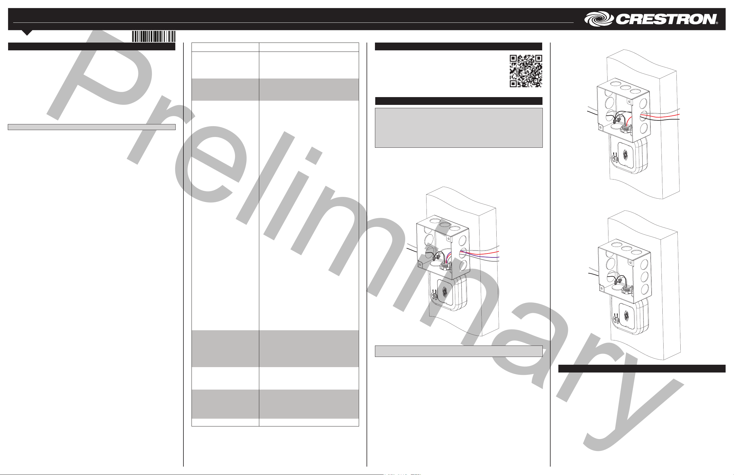
ZUMMESH-JBOX-5A-LV, ZUMMESH-JBOX-16A-LV,
and ZUMMESH-JBOX-20A-SW Wiring
100-277 Vac power
from breaker
Neutral
(white)
Hot (black)
NOTE: The 0–10 V dim - and 0–10 V dim + wires are not present on the
ZUMMESH-JBOX-20A-SW.
To 0-10 V
Controlled load
Neutral (white)
Switched output (red)
0-10 V dim + (purple)
0-10 V dim - (gray)
ZUMMESH-JBOX-20A-PLUG Wiring
100-277 Vac power
from breaker
Neutral (white)
Hot (black)
ZUMMESH-JBOX-PSU Wiring
100-277 Vac power
from breaker
Neutral (white)
Hot (black)
15 or 20 A receptacle
Neutral (white)
Switched output (red)
Hot (black) to
unswitched
receptacles
Test the Loads
Press the TEST button to toggle the connected loads.
Press and hold the TEST button to cycle dim the connected loads (dimmer models only).
Page 2

Preliminary
Basic Room Setup
A basic single-room Zūm system consists of Zūm mesh devices, i.e., dimmers, switches,
keypads, and sensors. The Zūm mesh devices in the room communicate directly with
each other without the need for a centralized gateway or processor.
To set up a new single-room Zūm system, do the following:
Step 1a: Create a new single-room Zūm system.
Step 2: Add Zūm mesh devices to the room.
Step 3: Finish creating the single-room Zūm system.
To modify an existing Zūm system, do the following:
Step 1b: Place the system in Joining mode.
Step 2: Add Zūm mesh devices to the room.
Step 3: Finish creating the single-room Zūm system.
Step 1a – Creating a Single-Room Zūm System
To create a new single-room Zūm system, rst form a new room.
NOTE: This can be performed on only one device in the room.
NOTE: The device that is used to create the room is automatically added to the room.
The device does not need to be added to the room.
NOTE: A room can be created only from an ac-powered device.
Start a New Single-Room System with a Keypad, Dimmer, or Switch
Press the bottom button 5 times, and then press and hold the bottom button for
2 seconds. If the device is not factory fresh, hold the button for 10 seconds. Release the
button when the LED lights. The LED illuminates for 3 seconds and then slowly ashes to
indicate that the room is in Joining mode and that other devices can join the room.
Step 1b – Expanding an Existing Single-Room Zūm System
To allow other devices to join the room, place the single-room Zūm system into Joining
mode. Joining mode can be enabled from any ac-powered device or battery keypad that
is already part of the room.
Expand a Single-Room Zūm System Using a Keypad
To enter Joining mode, press and hold both the top and bottom buttons for 5 seconds,
wait for the LED to light, and then tap the top button once, and then the bottom button
once.
5s
Expand a Single-Room Zūm System Using a J-box Device
To enter Joining mode, tap the SETUP button 2 times, and then tap the TEST button.
SETUP
TEST
Pressing any button on a device that is part of the network takes the system out of
joining mode. Joining mode ends automatically after 4 minutes.
SETUP
TEST
Factory Reset
Perform a factory reset when the device is removed from the network or to remove the
conguration settings. The device must also be factory reset if the device is being moved
to a different system.
NOTE: New-in-box devices do not need to be factory reset before joining a system.
To factory reset the device, press and hold the TEST and SETUP button for 10 seconds.
Release the button when the LED lights. The LEDs and output will turn on.
SETUP
TEST
10s
Install Network Bridge
The Zūm Network Bridge enables Zūm device setup from a mobile app and integrates a
stand-alone Zūm lighting control system with the Zūm hub (not supplied) for a centrally
managed, enterprise-wide lighting control system. The network bridge can be installed to
any J-box device.
1. Using a at-head screwdriver, remove the cover on the J-box device.
2. Ensure that the connector on the network bridge is aligned with the expansion port
on the J-box, and then insert the network bridge into the J-box device. The
network bridge snaps into place.
100-277 Vac power
from breaker
Neutral (white)
Hot (black)
Step 2 - Adding Zūm Mesh Devices to the Room
Adding Zūm mesh devices to a room is quick and easy. Add devices to the room when
the room is in Joining mode. Joining mode is automatically enabled after a single-room
Zūm system is started (see Step 1a). Joining mode can also be enabled manually (see
Step 1b).
The LEDs on all ac-powered devices in the system blink when the system is in Joining
2s or 10s
Start a Single-Room System with a J-Box Device
Press the SETUP button 5 times, and then press and hold the SETUP button for
2 seconds. If the device is not factory fresh, hold the button for 10 seconds. Release the
button when the LED lights. The LED illuminates for 3 seconds and then slowly ashes to
indicate that the room is in Joining mode and that other devices can join the room.
SETUP
TEST
2s or 10s
mode.
NOTE: A Zūm mesh device can belong to only one room.
NOTE: The Zūm mesh device used to create the room is already part of the network. It
does not need to be added to the network.
To add a J-box dimmer or switch to the room, press the SETUP button 3 times, and then
press and hold the SETUP button for 2 seconds. If the device is not factory fresh, hold
the button for 10 seconds. Release the button when the LED lights. The LED blinks
slowly to indicate that it is part of the room and that the room is still in Joining Mode.
SETUP
TEST
If necessary, the network bridge can be easily removed. To remove the network bridge,
do the following:
1. Between the J-box and the J-box device, press the side of the network bridge with
your thumb away from the J-box.
2. While pressing on the side of the network bridge, slightly lift the network bridge up
and out of the J-box device. The network bridge should easily remove from the
J-box device.
This product is Listed to applicable UL® Standards and requirements tested by Underwriters
Laboratories Inc.
Ce produit est homologué selon les normes et les exigences UL applicables par Underwriters
Laboratories Inc.
Federal Communications Commission (FCC) Compliance Statement
This device complies with part 15 of the FCC Rules. Operation is subject to the following
conditions:(1) This device may not cause harmful interference and (2) this device must accept any
interference received, including interference that may cause undesired operation.
CAUTION: Changes or modications not expressly approved by the manufacturer responsible for
compliance could void the user’s authority to operate the equipment.
NOTE: This equipment has been tested and found to comply with the limits for a Class B digital
device, pursuant to part 15 of the FCC Rules. These limits are designed to provide reasonable
protection against harmful interference in a residential installation. This equipment generates, uses
2s or 10s
Step 3 - Finishing the Single-Room Zūm System
Press any button on a device that has already joined the network to end the setup
process (e.g., the top button of a keypad or the SETUP button of a J-box device that is
blinking its LED).
SETUP
TEST
and can radiate radio frequency energy and, if not installed and used in accordance with the
instructions, may cause harmful interference to radio communications. However, there is no guarantee
that interference will not occur in a particular installation. If this equipment does cause harmful
interference to radio or television reception, which can be determined by turning the equipment off and
on, the user is encouraged to try to correct the interference by one or more of the following measures:
• Reorient or relocate the receiving antenna.
• Increase the separation between the equipment and receiver.
• Connect the equipment into an outlet on a circuit different from that to which the receiver is
connected.
• Consult the dealer or an experienced radio/TV technician for help.
Industry Canada (IC) Compliance Statement
CAN ICES-3(B)/NMB-3(B)
This equipment should be installed and operated with a minimum distance 20cm between the radiator
and your body Cet équipement doit être installé et utilisé à une distance minimale de 20 cm entre le
radiateur et votre corps.
This device complies with Industry Canada license-exempt RSS standard(s). Operation is subject to the
following two conditions: (1) this device may not cause interference, and (2) this device must accept any
interference, including interference that may cause undesired operation of the device.
Le présent appareil est conforme aux CNR d'Industrie Canada applicables aux appareils radio exempts
de licence. L'exploitation est autorisée aux deux conditions suivantes : (1) l'appareil ne doit pas produire
de brouillage, et (2) l'utilisateur de l'appareil doit accepter tout brouillage radioélectrique subi, même si
le brouillage est susceptible d'en compromettre le fonctionnement.
The product warranty can be found at www.crestron.com/warranty.
The specic patents that cover Crestron products are listed at patents.crestron.com.
Certain Crestron products contain open source software. For specic information, please visit
www.crestron.com/opensource.
Crestron, the Crestron logo,and Zūm are either trademarks or registered trademarks of Crestron
Electronics, Inc. in the United States and/or other countries. UL and the UL logo are either
trademarks or registered trademarks of Underwriters Laboratories, Inc. in the United States and/or
other countries. Other trademarks, registered trademarks, and trade names may be used in this
document to refer to either the entities claiming the marks and names or their products. Crestron
disclaims any proprietary interest in the marks and names of others. Crestron is not responsible for
errors in typography or photography.
This document was written by the Technical Publications department at Crestron.
©2017 Crestron Electronics, Inc.
Crestron Electronics, Inc. Installation Guide - DOC. 7863B
15 Volvo Drive Rockleigh, NJ 07647 (2048125)
Tel: 888.CRESTRON 11.17
Fax: 201.767.7576 Specications subject to
www.crestron.com change without notice.
 Loading...