

Page 1

Crestron TPMC-3X
®
Isys i/O
2.8” Handheld WiFi Touchpanel
Operations Guide
Page 2

This document was prepared and written by the Technical Documentation department at:
Crestron Electronics, Inc.
15 Volvo Drive
Rockleigh, NJ 07647
1-888-CRESTRON
Regulatory Compliance
As of the date of manufacture, the TPMC-3X has been tested and found to comply with specifications for CE
marking and standards per EMC and Radiocommunications Compliance Labelling.
Federal Communications Commission (FCC) Compliance Statement
This device complies with part 15 of the FCC rules. Operation is subject to the following conditions:
(1) this device may not cause harmful interference and (2) this device must accept any interference received,
including interference that may cause undesired operation.
CAUTION: Changes or modifications not expressly approved by the manufacturer responsible for compliance
could void the user’s authority to operate the equipment.
NOTE: This equipment has been tested and found to comply with the limits for a Class B digital device,
pursuant to part 15 of the FCC rules. These limits are designed to provide reasonable protection against harmful
interference in a residential installation. This equipment generates, uses and can radiate radio frequency energy
and if not installed and used in accordance with the instructions, may cause harmful interference to radio
communications. However, there is no guarantee that interference will not occur in a particular installation. If
this equipment does cause harmful interference to radio or television reception, which can be determined by
turning the equipment off and on, the user is encouraged to try to correct the interference by one or more of the
following measures:
Reorient or relocate the receiving antenna
Increase separation between the equipment and the receiver
Connect the equipment into an outlet on a circuit different from that to which the receiver is connected
Consult the dealer or an experienced radio/TV technician for help
Industry Canada (IC) Compliance Statement
Operation is subject to the following two conditions:
1. This device may not cause interferecne, and
2. This device must accept any interference, including interference that may cause undesired operation of the
device.
To satisfy RF exposure requirements, this device and its antenna must operate with a separation distance of at
least 20 centimeters from all persons and must not be colocated or operating in conjunction with any other
antenna or transmitter.
For operation within the 5.15-5.25 GHz band, it is restricted to indoor use.
All brand names, product names and trademarks are the property of their respective owners.
©2009 Crestron Electronics, Inc.
Page 3

Crestron TPMC-3X Isys i/O® 2.8” Handheld WiFi Touchpanel
Contents
Isys i/O® 2.8” Handheld WiFi Touchpanel: TPMC-3X 1
Introduction ...............................................................................................................................1
Features and Functions................................................................................................ 1
Applications.................................................................................................................4
Specifications ..............................................................................................................6
Physical Description.................................................................................................... 8
Setup ........................................................................................................................................ 12
Identity Code ............................................................................................................. 12
Battery Installation .................................................................................................... 12
Power......................................................................................................................... 13
Battery Calibration ....................................................................................................14
Configuring the Touchpanel...................................................................................... 15
General Use and Safety .............................................................................................28
Recommended Cleaning............................................................................................ 28
Programming Software............................................................................................................29
Earliest Version Software Requirements for the PC .................................................29
Programming with Crestron SystemBuilder.............................................................. 29
Programming with SIMPL Windows........................................................................ 29
Programming with VisionTools Pro-e....................................................................... 31
Embedded Applications.............................................................................................35
Example Program...................................................................................................... 36
Uploading and Upgrading........................................................................................................ 37
Establishing Communication.....................................................................................37
Programs, Projects and Firmware.............................................................................. 38
Program Checks ........................................................................................................38
Problem Solving ......................................................................................................................40
Troubleshooting......................................................................................................... 40
Reference Documents................................................................................................41
Further Inquiries........................................................................................................ 42
Future Updates ..........................................................................................................42
Software License Agreement................................................................................................... 43
Return and Warranty Policies.................................................................................................. 46
Merchandise Returns / Repair Service ......................................................................46
CRESTRON Limited Warranty.................................................................................46
Operations Guide – DOC. 6789C Contents • i
Page 4

Page 5

Crestron TPMC-3X Isys i/O® 2.8” Handheld WiFi Touchpanel
Isys i/O® 2.8” Handheld WiFi
Touchpanel: TPMC-3X
Introduction
Simply stated, the TPMC-3X Handheld Wifi Touchpanel from Crestron® delivers the
best remote control available for home theater and AV presentation, marrying style
and ergonomics with the ultimate in performance and ease of customization. Its sleek
form factor is easy to hold, with large tactile pushbuttons, electroluminescent
backlighting and a fully customizable video touchscreen to provide a wireless control
solution that is both intuitive and fun to use.
Features and Functions
• Sleek and ergonomic handheld design
• Stylish tabletop docking station
• Elegant gloss black finish
• Instant-Waking™ behavior with tilt sensor
• Works like an IR remote - with all the benefits of 2-way RF
• High performance 802.11a/b/g Wi-Fi wireless communications
• 50 feet (~15 meters) omnidirectional RF range indoors*
• Supports roaming between multiple Wi-Fi access points
• Long lasting lithium polymer rechargeable battery pack
• Widely spaced tactile pushbuttons
• White EL backlit button text
• 2.8” (72 mm) active matrix color touchscreen display
• High display brightness and contrast
• Wide 150 degree viewing angle
• 16-bit Isys i/O
• 240 x 320 resolution
• Dynamic graphics and text capability
• Synapse™ image rendering algorithm
• DNav dynamic menu objects
• Windows
• Wireless video from network cameras and servers
• WAV file audio feedback
• Programmable via SystemBuilder™ and Adagio
®
graphics
®
SideShow® enabled
®
Composer software
* Range is subject to environmental conditions.
Operations Guide – DOC. 6789C Isys i/O® 2.8” Handheld WiFi Touchpanel: TPMC-3X • 1
Page 6

Isys i/O® 2.8” Handheld WiFi Touchpanel Crestron TPMC-3X
The Ultimate Handheld Remote
Gone are the limitations of previous generation remotes and the frustration of using
them. The TPMC-3X offers seamless interaction with AV and environmental
systems, providing true feedback of all you settings and displaying metadata
information for all your digital media. Whether watching TV, choosing a movie or
music title, adjusting room temperature and lighting, checking the security system or
even monitoring live video right on the built-in touchscreen, the TPMC-3X affords a
user experience like no other handheld remote.
Wi-Fi Performance – Redefined!
Crestron has redefined Wi-Fi wireless performance with the TPMC-3X, achieving a
remarkable 50 feet (~15 meters) omnidirectional coverage indoors (subject to
environmental conditions), providing exceptional freedom of movement without
line-of-sight or even having to be in the same room. The TPMC-3X also supports
roaming* among multiple access points for extended coverage. The choice of
802.11a,b and g protocols affords reliable, high speed 2-way wireless performance in
virtually any RF environment. A network of one or more TPMC-3Xs can be set up in
minutes using a Crestron CEN-WAP-ABG-1G or CEN-WAP-ABG-CM Wireless
Access Point (both sold separately).
* For more information about roaming, please contact Crestron customer support.
Instant-Waking™
To ensure the most transparent user experience possible, the TPMC-3X has been
engineered to wake instantly at the press of a button, touch of the touchscreen or by
simply tilting the remote upright. Button presses are sent immediately just like an IR
remote but with none of IR’s limitations. So spontaneous actions like muting the
audio, pausing the video or changing the channel can be executed on the fly with just
a single button press.
Extended Battery Life
Instant waking also allows the TPMC-3X to be put to sleep within seconds of putting
it down, helping to extend its battery life for several days of typical usage on a single
charge. Even under continuous use at full brightness, the TPMC-3X lasts an
incredible five hours. Its fast charging, field replaceable lithium polymer battery
pack delivers optimum power in a very small, lightweight package.
Tactile Pushbuttons with Backlit Text
A complement of 27 tactile pushbuttons makes for a very intuitive user interface,
providing easy access to everything needed for watching TV and movies, listening to
music and controlling the entire room. Large, widely spaced buttons accommodate
hands and fingers of all sizes, minimizing the chance of an unintended button press.
Backlit button text affords excellent legibility for use in a darkened room.
The pushbuttons are comprised of 17 buttons designated for the most common
functions, a 5-way navigation pad, three context assignable “hard keys” beneath the
touchscreen, a thumb operated “More” button for advancing through the available
touchscreen pages and a system power button. Every button on the TPMC-3X is
fully programmable to allow precisely the control desired, whether simply adjusting
audio volume and flipping through channels, controlling a DVR or DVD player,
navigating onscreen setup menus or operating a pan/tilt camera.
2 • Isys i/O® 2.8” Handheld WiFi Touchpanel: TPMC-3X Operations Guide – DOC. 6789C
Page 7

Crestron TPMC-3X Isys i/O® 2.8” Handheld WiFi Touchpanel
Handheld Touchpanel Control
Custom touchpanel versatility is afforded through a brilliant 2.8” (72 mm) active
matrix touchscreen displaying stunning 16-bit color graphics and video. Dynamic
graphics and text capability enable the display of all kinds of useful data and alluring
eye candy, from channel preset icons, to room temperature and lighting levels, to
photos and video, to digital media playlists complete with metadata and cover art.
Crestron exclusive DNav and Synapse™ technologies enable system programmers to
produce amazing graphics faster and easier, using advanced dynamic control menus
and 3D effects. Full motion animations, multimode objects, PNG translucency,
transition effects and streaming video enhance the palette for creating GUIs that are
both eye catching and easy to use.
Support for Windows
Web-based content such as news feeds, sports scores, stock tickers, weather alerts,
media guides, appointment notifications and email messages all through a simple
network connection to a Windows® computer.
Wireless Video
Its built-in streaming video player makes it possible to monitor a security camera or
preview a DVD or television channel, right on the touchscreen display. Native
support for MJPEG streaming allows the TPMC-3X to display live video from a
variety of Web cameras and servers including the Crestron CEN-NVS100 Network
Video Streamer (sold separately).
®
SideShow® gives the TPMC-3X access to all kinds of PC and
Audio Feedback
Customized WAV files can be loaded on the TPMC-3X to add dimension to its
touchscreen graphics using personalized sounds, button feedback and voice prompts.
TableTop Docking Station/Charger
The TPMC-3X makes an elegant statement in any room, especially when placed on
its stylish docking station/charger (model TPMC-3X-DS, included). When docked,
the touchpanel sits at the ready, able to be used as a stationary tabletop controller
while charging. The docking hook incorporates a magnetic catch, ensuring secure
attachment while docked and an effortless transition between docked and handheld
use. The sleek, low profile base is weighted for excellent stability on any flat surface.
An optional wall mount docking station is also available (model TPMC-3X-DSW,
sold separately).
Operations Guide – DOC. 6789C Isys i/O® 2.8” Handheld WiFi Touchpanel: TPMC-3X • 3
Page 8

Isys i/O® 2.8” Handheld WiFi Touchpanel Crestron TPMC-3X
Applications
The following diagram illustrates a basic configuration that connects a TPMC-3X
WiFi touchpanel to a control system via a wireless access point (WAP).
TPMC-3X in a Simple Network
The distance between the TPMC-3X and the CEN-WAP-ABG-1G
(or CEN-WAP-ABG-CM) should not exceed 50 feet (~15 meters).
4 • Isys i/O® 2.8” Handheld WiFi Touchpanel: TPMC-3X Operations Guide – DOC. 6789C
Page 9

Crestron TPMC-3X Isys i/O® 2.8” Handheld WiFi Touchpanel
The following diagram presents a more complex configuration. In this scenario, the
WAP is connected to a port on the control system’s C2ENET-2 card. The other port
is connected to the corporate LAN. The card’s internal firewall controls data flow,
thus isolating the two subnets.
NOTE: When using a dual-port Ethernet card, Ports A & B must be different
subnets (e.g., Port A = 128.x.x.x; Port B = 192.x.x.x).
For additional information on setting up and understanding an Ethernet network,
refer to the latest version of the Crestron e-Control Reference Guide (Doc. 6052).
TPMC-3X with Multiple Networks
Operations Guide – DOC. 6789C Isys i/O® 2.8” Handheld WiFi Touchpanel: TPMC-3X • 5
Page 10

Isys i/O® 2.8” Handheld WiFi Touchpanel Crestron TPMC-3X
Specifications
Specifications for the TPMC-3X are listed in the following table.
TPMC-3X Specifications
SPECIFICATION DETAILS
Touchscreen Display
Display Type Transflective TFT active matrix color LCD
Size 2.8 inch (72 mm) diagonal
Aspect Ratio 3:4 QVGA (portrait orientation)
Resolution 240 x 320 pixels
Brightness 350 nits typical
Contrast 500:1 typical
Color Depth 16-bit, 64k colors
Viewing Angle ±75º horizontal, +75º/-55º vertical
Illumination LED backlit
Touchscreen Resistive membrane
Memory
SDRAM 128 MB
Flash 256 MB
Maximum Project Size 24 MB
Graphic Engine
Embedded PC Applications1 Crestron MJPEG Viewer
RF Wireless
RF Transceiver
Range
Gateway
Video
Streaming Formats
Audio
Hardware Features Built-in speaker
Audio Feedback (WAV)
®
Isys i/O
graphics; 65,536 colors; Synapse™ image
rendering algorithm; multi-mode objects;
DNav dynamic menu objects; dynamic
graphics and text; Windows® SideShow®
support; PNG translucency; full motion (60
fps) animation; transition effects
IEEE 802.11a/b/g Wi-Fi, 5.8 or 2.4 GHz
2-way RF, static IP or dynamic IP via
DHCP, 64 and 128-bit WEP encryption,
WPA and WPA2-PSK with TKIP and AES
50 feet (~15 meters), subject to
environmental conditions, supports roaming
among multiple access points
Requires a CEN-WAP-ABG or similar
802.11a/b/g wireless access point and
Ethernet enabled Crestron 2-Series control
system (all sold separately)
MJPEG via Crestron MJPEG Viewer, with
support for Crestron CEN-NVS100 Network
Video Streamer (sold separately)
8 and 16-bit PCM, mono & stereo,
8-44.1kHz sampling rates
engine, 16-bit non-palette
(Continued on following page)
6 • Isys i/O® 2.8” Handheld WiFi Touchpanel: TPMC-3X Operations Guide – DOC. 6789C
Page 11

Crestron TPMC-3X Isys i/O® 2.8” Handheld WiFi Touchpanel
TPMC-3X Specifications (Continued)
SPECIFICATION DETAILS
Tilt Sensor
Wakes touchpanel within 0.5 seconds when
unit’s physical orientation is moved from
horizontal to vertical
Battery
Battery Type
Lithium polymer, 3.7 Volt, 1000 mAh
(included)
Usage per Charge 5 hours continuous at full brightness
Charging Time 2 hours
Cycle Life >300 cycles (80% capacity)
Power Requirements
TPMC-3X-DS Docking
1.5 Amps @ 12 Volts DC
Station/Charger (included)
Power Supply (included) 0.6 Amps @ 100-240 Volts AC, 50-60 Hz
Default IP ID 03
Minimum 2-Series Control
System Update File
2, 3
Version 3.155.1240 or later
Environmental
Temperature 32º to 104º F (0º to 40º C)
Humidity 10% to 90% RH (non-condensing)
Heat Dissipation 5 BTU/Hr
Enclosure
Construction Plastic, integral docking station port
Dimensions
Height
1.04 in (27 mm)
6.34 in (161 mm) docked
Width
2.55 in (65 mm)
4.58 in (117 mm) docked
Depth
7.94 in (202 mm)
6.30 in (160 mm) docked
Weight 7 oz (187 g)
Included Accessories
Power Supply
Input: 100-240 VAC 0.6A 50/60 Hz,
Output: 12 Volt DC, 1.5A
TPMC-3X-BTP Internal Battery Pack
TPMC-3X-DS Docking Station/Charger
Available Accessories
CEN-WAP-ABG-1G
802.11a/b/g Wireless Access Point,
Wall Mount
CEN-WAP-ABG-CM
802.11a/b/g Wireless Access Point,
Ceiling Mount
TPMC-3X-DSW Wall Mount Docking Station/Charger
1. Refer to website or contact Crestron for a current list of embedded applications. To ensure reliable
performance, new applications are available only from Crestron through firmware updates.
2. The latest software versions can be obtained from the Crestron website. Refer to the NOTE following
these footnotes.
3. Crestron 2-Series control systems include the AV2 and PRO2. Consult the latest Crestron Product
Catalog for a complete list of 2-Series control systems.
Operations Guide – DOC. 6789C Isys i/O® 2.8” Handheld WiFi Touchpanel: TPMC-3X • 7
Page 12

Isys i/O® 2.8” Handheld WiFi Touchpanel Crestron TPMC-3X
NOTE: Crestron software and any files on the website are for authorized Crestron
dealers and Crestron Authorized Independent Programmers (CAIP) only. New users
may be required to register to obtain access to certain areas of the site (including the
FTP site).
Physical Description
This section provides information on the connections, controls and indicators
available on your TPMC-3X.
TPMC-3X Physical View
Battery must be recycled. Deliver the battery to an appropriate recycling facility.
8 • Isys i/O® 2.8” Handheld WiFi Touchpanel: TPMC-3X Operations Guide – DOC. 6789C
Page 13
Crestron TPMC-3X Isys i/O® 2.8” Handheld WiFi Touchpanel
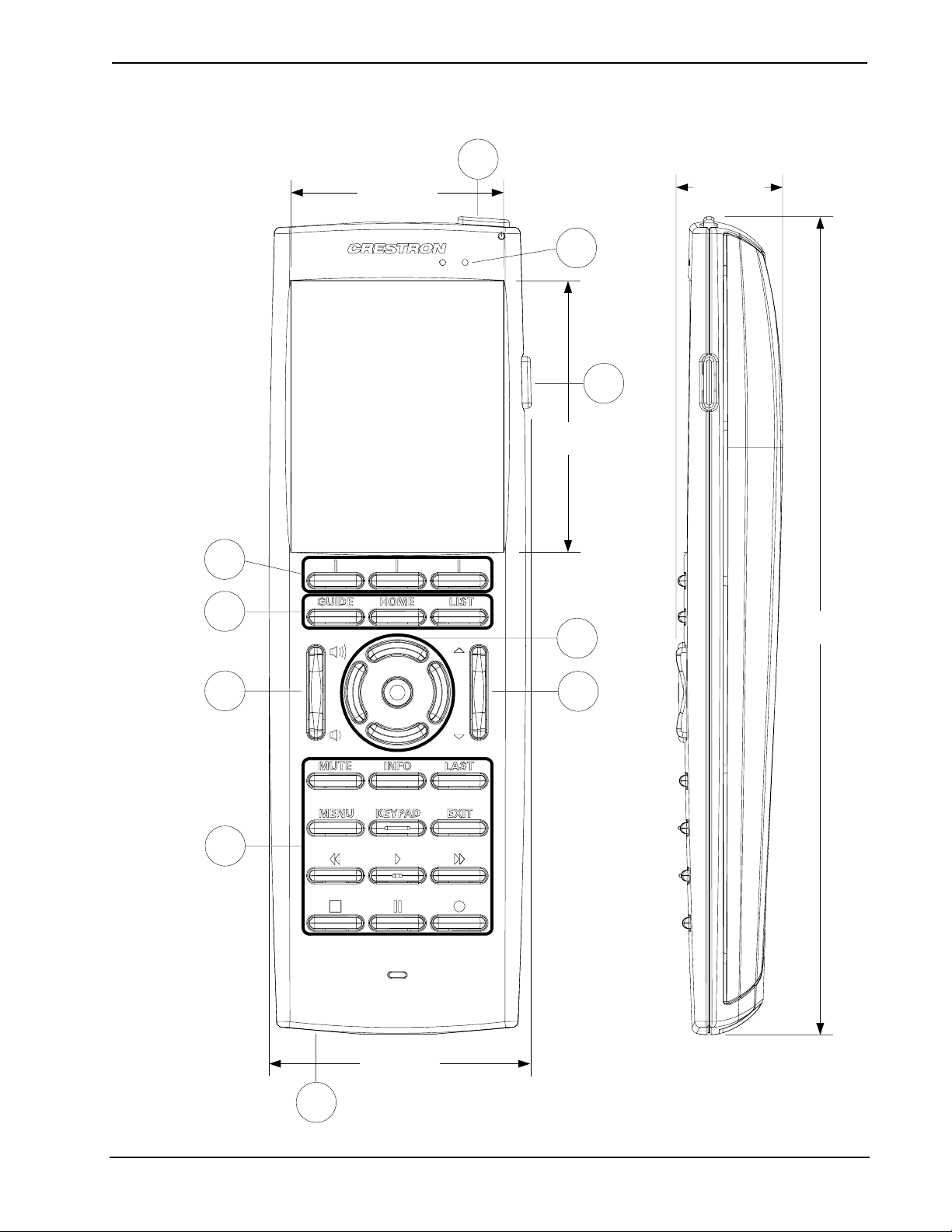
TPMC-3X Overall Dimensions (Front and Side Views)
1
2.07 in
(53 mm)
2
3
2.64 in
(67 mm)
1.04 in
(27 mm)
4
5
7
6
8
7.94 in
(202 mm)
5
2.55 in
(65 mm)
9
Operations Guide – DOC. 6789C Isys i/O® 2.8” Handheld WiFi Touchpanel: TPMC-3X • 9
Page 14

Isys i/O® 2.8” Handheld WiFi Touchpanel Crestron TPMC-3X
TPMC-3X-DS Docking Station/Charger Dimensions (Front, Side, Rear and Bottom Views)
4.26 in
(109 mm)
5.88 in
(150 mm)
FROM (included)
DC POWER PACK
4.58 in
(117 mm)
10 • Isys i/O® 2.8” Handheld WiFi Touchpanel: TPMC-3X Operations Guide – DOC. 6789C
Page 15

Crestron TPMC-3X Isys i/O® 2.8” Handheld WiFi Touchpanel
Connectors, Controls & Indicators
#
CONNECTORS
CONTROLS &
INDICATORS
1
,
DESCRIPTION
1 Power (top)
2 Charge
3 More (right side)
4 Hard Keys
5 Functions
6 Volume
7 Navigation Pad
8 Up/Down
9 USB* (bottom)
* USB port is for installer use only.
(1) Programmable pushbutton, performs
hardware reset if held for >10 seconds
(1) Green LED, indicates charging status
when docked
(1) Programmable thumb operated side
button
(3) Programmable pushbuttons below
touchscreen
(15) Programmable pushbuttons with white
backlit labeling for GUIDE, HOME, LIST,
MUTE, INFO, LAST, MENU, KEYPAD, EXIT
and icons for Rewind, Play, Forward, Stop,
Pause, Record
(1) Programmable rocker button with white
backlit volume “Raise” and “Lower” icons
(5) Programmable pushbuttons comprising a
5-way thumbpad (4-way navigation plus
“Enter”)
(1) Programmable rocker button with white
backlit “Up” and “Down” arrows
(1) Mini Type AB female (behind battery
cover);
USB 1.1 computer console port, cable
included
Operations Guide – DOC. 6789C Isys i/O® 2.8” Handheld WiFi Touchpanel: TPMC-3X • 11
Page 16

Isys i/O® 2.8” Handheld WiFi Touchpanel Crestron TPMC-3X
Setup
Identity Code
The IP ID is set within the TPMC-3X’s table using Crestron Toolbox™. For
information on setting an IP table, refer to the Crestron Toolbox help file. The IP IDs
of multiple TPMC-3X devices in the same system must be unique.
When setting the IP ID, consider the following:
• The IP ID of each unit must match an IP ID specified in the SIMPL™
Windows program.
• Each device using IP to communicate with a control system must have a
unique IP ID.
Battery Installation
Perform the following procedure to install the TPMC-3X-BTP battery pack in a
TPMC-3X touchpanel:
1. Place the touchpanel screen side down on a clean, soft surface.
2. Remove the battery compartment cover on the rear of the touchpanel.
3. Carefully connect the multi-pin connector of the TPMC-3X-BTP with the
corresponding connector inside the battery compartment. The pin side of the
connector should be facing upward (toward the rear of the touchpanel). Red
wires should be above black wires (toward the top of the touchpanel).
Ensure the connector is fully seated.
4. Place the TPMC-3X-BTP in the battery compartment, oriented so the wires
for the multi-pin connector are on the bottom. Refer to the photo on the
following page.
12 • Isys i/O® 2.8” Handheld WiFi Touchpanel: TPMC-3X Operations Guide – DOC. 6789C
Page 17

Crestron TPMC-3X Isys i/O® 2.8” Handheld WiFi Touchpanel
TPMC-3X-BTP in Battery Compartment of TPMC-3X
5. Re-attach the battery compartment cover.
Power
To charge its internal battery pack, the TPMC-3X must be placed on the included
TPMC-3X-DS docking station/charger. Connect the included power pack to the
TPMC-3X-DS docking station/charger.
NOTE: Before using the TPMC-3X for the first time, charge its internal battery for
at least two hours by placing on the TPMC-3X-DS docking station/charger. The
green LED on the front of the TPMC-3X will blink while the battery is charging.
It takes the TPMC-3X about two hours to recharge while in use. A fully charged
battery can provide up to five hours of use at the full screen brightness setting.
The TPMC-3X has a removable battery pack. With a properly maintained battery,
the design should retain 80% of its original capacity at 300 full charge and discharge
cycles. You may choose to replace your battery when it no longer holds sufficient
charge to meet your needs.
NOTE: When not using the TPMC-3X, store the unit on its docking station/charger.
NOTE: The TPMC-3X can become unresponsive when battery strength is low.
Operations Guide – DOC. 6789C Isys i/O® 2.8” Handheld WiFi Touchpanel: TPMC-3X • 13
Page 18

Isys i/O® 2.8” Handheld WiFi Touchpanel Crestron TPMC-3X
Battery Calibration
For optimum performance after shipping or any time the unit’s power has been off
for an extended period of time, Crestron recommends the following procedure be
performed:
1. Place the unit on its docking station/charger and connect AC power.
2. Allow the unit to charge completely. (The green LED should be steady on
for 15 minutes.)
3. Remove panel from the docking station/charger.
4. From the main setup screen, touch Diagnostics, then touch Battery Diags
to go to the Battery Diagnostics screen. Touch Recondition Battery, then
touch YES, Recondition Battery to confirm. (Refer to “Configuring the
Touchpanel” which starts on page 15.)
5. Wait for the unit to shut off. This takes approximately five hours. Leave the
unit off the dock the entire time. During this operation, the Battery
Reconditioning screen shown on page 25 will be displayed until the unit
shuts off.
6. Place the unit back on the docking station and allow it to charge completely.
7. Unit is now ready for normal operation.
14 • Isys i/O® 2.8” Handheld WiFi Touchpanel: TPMC-3X Operations Guide – DOC. 6789C
Page 19

Crestron TPMC-3X Isys i/O® 2.8” Handheld WiFi Touchpanel
Configuring the Touchpanel
When power is applied to the unit for the first time, the following screen appears.
Initial Opening Screen
Touch the screen to display the following TPMC-3X setup screen.
Setup Screen
The setup screen enables basic configuration procedures prior to regular operation of
the touchpanel.
NOTE: During regular operation of the touchpanel, there are three ways to activate
the setup functions:
1. Place a button on the project main page and assign the reserved join number
(17242) that activates setup.
2. Press hard keys 1, 2, 3, and 4 in sequence twice (i.e. press 1, 2, 3, 4, 1, 2, 3, 4)
within a five second period. For hard key locations, refer to “Pushbutton
Programming” on page 34.
3. If the system bar is visible at the top of the display, you can also access the
setup screen by touching the Crestron swirl logo in the upper left corner.
Operations Guide – DOC. 6789C Isys i/O® 2.8” Handheld WiFi Touchpanel: TPMC-3X • 15
Page 20

Isys i/O® 2.8” Handheld WiFi Touchpanel Crestron TPMC-3X
Indicators
The top of the setup screen contains the system bar, which includes bar graph
indicators for battery strength and Wi-Fi signal strength.
Panel Setup Options
These setup options control the basic operation of the TPMC-3X.
WiFi Setup
Touch WiFi Setup to display information about your WiFi Signal Strength, WAP
Connection, Control Connection, MAC address, IP Address and to gain access to tie
IP Config, WiFi Access Point, CtrlSys IP Address and Performance Options
screens. Touch Back to return to the main setup screen.
WiFi Setup Screen
NOTE: It may take 5-10 seconds for the IP address to show once the WAP
Connection indicator has turned green.
When you enter the screens for WiFi Access Point, CntrlSystem IP Address and
IP Config, you will find a keyboard application at the bottom of each screen. The
keyboard uses the navigation pad (up, down, left and right) to select a character to
type. The center button on the navigation pad will type the selected character.
On-screen Keyboard
There are different characters in each row. You can move between rows using the
up/down buttons and move within a row using the left/right buttons.
There are a few “shortcut” keys: The top six hard keys are mapped according to the
legend at the bottom of the screen (BSpc, Tab>>, Delete, OK, <<Tab and Cancel).
The volume up/down and ▲/▼ keys on either side of the navigation pad also have
some shortcuts to help navigate around text and list boxes. The volume up/down
16 • Isys i/O® 2.8” Handheld WiFi Touchpanel: TPMC-3X Operations Guide – DOC. 6789C
Page 21

Crestron TPMC-3X Isys i/O® 2.8” Handheld WiFi Touchpanel
buttons act as the up and down arrow keys (use to select items in a list box). The ▲
and ▼ buttons can be used to move the cursor within a text string.
WiFi Access Point
From the WiFi Setup screen, touch WiFi Access Point to display the Wireless
Information screen, which allows you to set up the parameters used to communicate
with the control system via a wireless access point (WAP). Crestron recommends
using a dedicated CEN-WAP-ABG-1G or CEN-WAP-ABG-CM (both sold
separately) for each TPMC-3X in the system.
Wireless Information Screen
A list of available access points in shown. Use the volume up/down buttons to scroll
through the list. Select the access point and touch Edit to configure. With DHCP
enabled, simply enter your Network key.
Touch the appropriate hard key for Tab>> or <<Tab to navigate editable fields.
Touch the appropriate hard key for OK to save settings or for Cancel to exit without
saving.
Wireless Information Editing Screen
Operations Guide – DOC. 6789C Isys i/O® 2.8” Handheld WiFi Touchpanel: TPMC-3X • 17
Page 22

Isys i/O® 2.8” Handheld WiFi Touchpanel Crestron TPMC-3X
From the main Wireless Information screen, touch Advanced to access the
Advanced Wireless Information screen.
Advanced Wireless Information Screen
This screen allows you to Edit/Delete Preferred Access Points, View WiFi
Connection Log… and also to view << IP Info and WiFi Info >>.
CntrlSystem IP Address
From the WiFi Setup screen, touch CntrlSystem IP Address to display the Control
System Information screen, which allows you to Enable Autodiscovery and Use
Hostname Lookup as well as enter the IP Address, Port and IP ID.
Touch the appropriate hard key for Tab>> or <<Tab to navigate editable fields.
Touch the appropriate hard key for OK to save settings or for Cancel to exit without
saving.
NOTE: The control system connection may not be made until you exit setup.
Control System Information Screen
18 • Isys i/O® 2.8” Handheld WiFi Touchpanel: TPMC-3X Operations Guide – DOC. 6789C
Page 23

Crestron TPMC-3X Isys i/O® 2.8” Handheld WiFi Touchpanel
IP Config
From the WiFi Setup screen, touch IP Config to display the IP Settings screen.
You can select USE DHCP to automatically assign an IP address or you can select
USE STATIC, which allows you to manually enter an IP Address, Subnet Mask and
Gateway.
The TPMC-3X ships with DHCP enabled by default.
IP Settings Screen
If you are using a static IP address, touch DNS Servers to enter the DNS Servers
screen. Here, you can enter a specific Main DNS, Alternate DNS, Main WINS and
Alternate WINS. Touch IP Settings to return to the IP Settings screen.
Touch the appropriate hard key for Tab>> or <<Tab to navigate editable fields.
Touch the appropriate hard key for OK to save settings or for Cancel to exit without
saving.
DNS Servers Screen
Operations Guide – DOC. 6789C Isys i/O® 2.8” Handheld WiFi Touchpanel: TPMC-3X • 19
Page 24

Isys i/O® 2.8” Handheld WiFi Touchpanel Crestron TPMC-3X
Performance Options
From the WiFi Setup screen, touch Performance Options to display the
Performance Options screen, where you can select High Performance Mode or
Extended Battery Life Mode.
Performance Options Screen
Audio Setup
Touch Audio Setup to display the Audio Settings screen, with controls for Master
Volume and Mute as well as buttons providing access to the Key Click Settings and
Wav Settings screens. Touch Back to return to the main setup screen.
Audio Settings Screen
20 • Isys i/O® 2.8” Handheld WiFi Touchpanel: TPMC-3X Operations Guide – DOC. 6789C
Page 25

Crestron TPMC-3X Isys i/O® 2.8” Handheld WiFi Touchpanel
Key Click Settings
Touch Key Click Settings to enter the Key Click Settings screen, which has controls
for Key Click Volume and Mute, as well as controls to turn the key click sound that
occurs when the panel is docked on or off. Touch Back to return to the Audio
Settings screen.
Key Click Settings Screen
Wav Settings
Touch Wav Settings to enter the Wav Settings screen, which has controls for Wav
Volume and Mute as well as a Play Test Wav button. Touch Back to return to the
Audio Settings screen.
Wav Settings Screen
Operations Guide – DOC. 6789C Isys i/O® 2.8” Handheld WiFi Touchpanel: TPMC-3X • 21
Page 26

Isys i/O® 2.8” Handheld WiFi Touchpanel Crestron TPMC-3X
Standby Setup
Touch Standby Setup to enter the Standby Timeouts screen, which has controls for
adjusting standby timeout when the TPMC-3X is docked and undocked, as well as a
Power Off timeout when the touchpanel is undocked. Touch Back to return to the
main setup screen.
Standby Timeouts Screen
Diagnostics
Touch Diagnostics to enter the Diagnostics screen. This screen will display Total
RAM, Free RAM and provide buttons for access to other screens, such as Keypad
Test, Touch Test, WiFi Diags, Battery Diags, Tilt Test and Test Mic. Touch Back
to return to the main setup screen.
Diagnostics Screen
22 • Isys i/O® 2.8” Handheld WiFi Touchpanel: TPMC-3X Operations Guide – DOC. 6789C
Page 27

Crestron TPMC-3X Isys i/O® 2.8” Handheld WiFi Touchpanel
Keypad Test
Touch Keypad Test to view the Keypad Test Screen. Pressing the corresponding
button on the TPMC-3X will cause its likeness on the screen to light up. Touch Back
to return to the Diagnostics screen.
Keypad Test Screen
Touch Test
From the Diagnostics screen, the Touch Test button takes you to a screen for
calibrating the TPMC-3X touchscreen. Touch Calibrate to begin screen calibration.
The calibration screen will show a crosshair in the center. Touch the crosshair and it
will move to another location on the screen. Continue to touch the crosshair as it
appears at each new location. When the process is finished, a ”Calibration
Complete” message will appear. Touch the screen to return to the Touch Test screen.
Then touch Return to go back to the Diagnostics screen.
Touch Test Screen
Operations Guide – DOC. 6789C Isys i/O® 2.8” Handheld WiFi Touchpanel: TPMC-3X • 23
Page 28

Isys i/O® 2.8” Handheld WiFi Touchpanel Crestron TPMC-3X
WiFi Diags
From the Diagnostics screen, touch WiFi Diags to enter the WiFi Diagnostics
screen, which displays SSID, BSSID, RSSI, Signal Strength, MAC Connection and IP
Addr and has indicators for WAP Connection and Control Connection. Touch Back
to return to the Diagnostics screen.
WiFi Diagnostics Screen
Battery Diags
From the Diagnostics screen, touch Battery Diags to enter the Battery Diagnostics
screen. This screen displays the battery’s state (e.g. charging), level (in percent),
amount of current remaining and amount of voltage remaining. In addition, it
contains controls to Reset Battery Gauge and Recondition Battery. Touch Back to
return to the Diagnostics screen.
NOTE: The field at the bottom of the screen is to be used when under the
supervision of a Crestron technical support representative during telephone support.
Battery Diagnostics Screen
24 • Isys i/O® 2.8” Handheld WiFi Touchpanel: TPMC-3X Operations Guide – DOC. 6789C
Page 29

Crestron TPMC-3X Isys i/O® 2.8” Handheld WiFi Touchpanel
Touch Reset Battery Gauge to recalibrate the battery gauge. The Confirm Reset
screen will appear. Touch YES, Reset Gauge to reset the gauge or touch Back to
return to the Battery Diagnostics screen.
NOTE: The gauge should be reset after any battery replacement.
Confirm Reset Screen
Touch Recondition Battery to drain and recondition the TPMC-3X’s battery. The
Confirm Recondition screen will appear.
Confirm Recondition Screen
Touch YES, Recondition Battery to start the process. The Battery Reconditioning
screen will appear.
Operations Guide – DOC. 6789C Isys i/O® 2.8” Handheld WiFi Touchpanel: TPMC-3X • 25
Page 30

Isys i/O® 2.8” Handheld WiFi Touchpanel Crestron TPMC-3X
Battery Reconditioning Screen
Tilt Test
From the Diagnostics screen, touch Tilt Test to enter the Tilt Sensor Test screen.
The text in the box should change from Flat to Tilt when the TPMC-3X is held
upright and from Tilt to Flat when it is placed flat, for example on a desk.
This screen also contains Tilt Wakes Panel controls, which determine whether tilting
the panel upright when power is off will turn power on and wake the panel.
NOTE: When the panel is in a standby condition (where just the display is off as
opposed to power being off) tilting it upright will always wake the panel, regardless
of the Tilt Wakes Panel selection.
Touch Back to return to the Diagnostics screen.
Tilt Sensor Test Screen
Test Mic
Touch Test Mic to start a microphone test. The panel will record audio from the
built-in microphone for five seconds, then play back the recording.
26 • Isys i/O® 2.8” Handheld WiFi Touchpanel: TPMC-3X Operations Guide – DOC. 6789C
Page 31

Crestron TPMC-3X Isys i/O® 2.8” Handheld WiFi Touchpanel
System Msgs Enabled
From the main setup screen, touch System Msgs Enabled to permit display of
system messages.
About
From the main setup screen, touch About to display a screen that shows software
and OS version information. Touch OK to remove the About screen.
Brightness Options
These setup options control the appearance of the TPMC-3X.
LCD Settings
From the main setup screen, touch LCD Settings to enter the Display Settings
screen, with controls for screen brightness when the TPMC-3X is docked and when
it is undocked. Lower brightness settings extend battery life. This screen also allows
you to turn the Hardkey Wakes LCD option On or Off. When On, pressing a hard
key or tilting the panel will turn on the LCD display if the display is off. Touch Back
to return to the main setup screen.
Display Settings Screen
Operations Guide – DOC. 6789C Isys i/O® 2.8” Handheld WiFi Touchpanel: TPMC-3X • 27
Page 32

Isys i/O® 2.8” Handheld WiFi Touchpanel Crestron TPMC-3X
Keypad Settings
From the main setup screen, touch Keypad Settings to enter the Keypad Settings
screen, with controls for keypad brightness when the TPMC-3X is docked and when
it is undocked. Lower brightness settings extend battery life. This screen also
provides a Keypad Test button, which is the same as the one described earlier. Refer
to “Diagnostics” which starts on page 22. Touch Back to return to the main setup
screen.
Keypad Settings Screen
Save & Exit
From the main setup screen, touch Save & Exit to save any setup changes you have
made and exit to normal operation mode.
General Use and Safety
WARNING: To avoid possible damage to the unit, do not use the touchpanel in the
rain or expose to unnecessary moisture.
Recommended Cleaning
Keep the surface of the touchscreen free of dirt, dust or other materials that could
degrade optical properties. Long-term contact with abrasive materials can scratch the
surface, which may detrimentally affect image quality.
For best cleaning results, use a clean, damp, non-abrasive cloth with any
commercially available non-ammonia glass cleaner. Bezels may not provide a
complete watertight seal. Therefore, apply cleaning solution to the cloth rather than
the surface of the touchscreen. Wipe touchscreen clean and avoid getting moisture
beneath the bezels.
28 • Isys i/O® 2.8” Handheld WiFi Touchpanel: TPMC-3X Operations Guide – DOC. 6789C
Page 33

Crestron TPMC-3X Isys i/O® 2.8” Handheld WiFi Touchpanel
Programming Software
Have a question or comment about Crestron software?
Answers to frequently asked questions (FAQs) can be viewed in the Online Help
section of the Crestron website. To post a question or view questions you have
submitted to Crestron’s True Blue Support, log in at http://support.crestron.com.
First-time users will need to establish a user account.
Earliest Version Software Requirements for the PC
NOTE: Crestron recommends that you use the latest software to take advantage of
the most recently released features. The latest software is available from the Crestron
website.
Crestron has developed an assortment of Windows-based software tools to develop
a controlled system. For the minimum recommended software versions, visit the
Version Tracker page of the Crestron website (www.crestron.com/versiontracker
).
Configuration Manager
Programming with Crestron SystemBuilder
Crestron SystemBuilder is the easiest method of programming but does not offer as
much flexibility as SIMPL Windows. For additional details, download
SystemBuilder from the Crestron website and examine the extensive help file.
Programming with SIMPL Windows
NOTE: While SIMPL Windows can be used to program the TPMC-3X, it is
recommended to use SystemBuilder for configuring a system.
SIMPL Windows is Crestron’s premier software for programming Crestron control
systems. It is organized into two separate but equally important “Managers”.
Configuration Manager is the view where programmers “build” a Crestron control
system by selecting hardware from the Device Library.
1. To incorporate the TPMC-3X into the system, drag the TPMC-3X from the
Touchpanels | Touchpanels (Ethernet folder of the Device Library and drop
it in the System Views.
Operations Guide – DOC. 6789C Isys i/O® 2.8” Handheld WiFi Touchpanel: TPMC-3X • 29
Page 34

Isys i/O® 2.8” Handheld WiFi Touchpanel Crestron TPMC-3X
Locating the TPMC-3X in the Device Library
2. The system tree of the control system displays the device in the appropriate
slot with an IP ID as shown in the following illustration.
C2Net Device, Slot 8
3. Additional TPMC-3X devices are assigned different IP ID numbers as they
are added.
4. If necessary, double click a device to open the “Device Settings” window
and change the IP ID, as shown in the following figure.
30 • Isys i/O® 2.8” Handheld WiFi Touchpanel: TPMC-3X Operations Guide – DOC. 6789C
Page 35

Crestron TPMC-3X Isys i/O® 2.8” Handheld WiFi Touchpanel
p
“Device Settings: Crestron TPMC-3X” Window
5. The ID code specified in the SIMPL Windows program must match the IP
ID of each unit.
Program Manager
Multi-mode objects offer high-
erformance programming!
Program Manager is the view where programmers “program” a Crestron control
system by assigning signals to symbols.
The symbol can be viewed by double clicking on the icon or dragging it into Detail
View. Each signal in the symbol is described in the SIMPL Windows help file (F1).
Programming with VisionTools Pro-e
Touchpanel screens should be created in VisionTools® Pro-e (VT Pro-e) to allow
accessing the embedded applications, switching of source signals to desired outputs
as well as selection of the system mode. There are no special programming
requirements to use the functions of the TPMC-3X in a room control system.
Multi-Mode Objects
The single most advanced VT Pro-e high performance programming technique
involving the TPMC-3X is the concept of multi-mode objects. A multi-mode object
(i.e. button, legend, etc.) is an object drawn on a VT Pro-e page that can have one or
more active and inactive visible settings (modes).
For examples, refer to www.crestron.com/exampleprograms
mode object examples. This file contains the VT Pro-e touchpanel files and SIMPL
Windows files that illustrate the high-performance capabilities of multi-mode
objects.
WAV File Audio Messages
and search for multi-
The TPMC-3X touchpanels are capable of playing audio messages as system
prompts and responses. These files are recorded as WAV files on a PC using an
audio utility such as Sound Recorder that is packaged with Microsoft Windows
95/98/Me/XP/NT/2000/Vista/7™. Files from other sources may also be converted to
an acceptable format by using this or a similar utility. Many other audio utilities are
available commercially or as shareware. The TPMC-3X touchpanels only accept the
following WAV file formats: PCM, 8 and 16 bit, 8 – 44.1kHz, mono and stereo.
For more information about how to use Sound Recorder, refer to its User’s Guide
and extensive help information provided with the software. Also refer to the help file
Operations Guide – DOC. 6789C Isys i/O® 2.8” Handheld WiFi Touchpanel: TPMC-3X • 31
Page 36

Isys i/O® 2.8” Handheld WiFi Touchpanel Crestron TPMC-3X
in VT Pro-e to learn how to use its audio tool, Sound Manager, to attach WAV files
to a touchpanel project.
Pre-recorded WAV files for voice prompts and responses are available from
Crestron. These files can be stored into and programmed for use in the touchpanel
directly or may be edited with the Sound Recorder. For example, the individual files
can be combined to create custom messages.
NOTE: Touchpanel WAV files can be obtained from the Wave LC Library of the
Crestron FTP site.
Bit Depth and File Size
A balance of performance and quality can be achieved by using VT Pro-e to
configure the size of graphics in a project. Read this section to learn about bit depth
and how to maximize the quality and performance of a TPMC-3X project.
Bit depth refers to the number of memory bits used to store color data for each pixel
in a raster image. A touchpanel raster image consists of a rectangular grid of picture
elements (pixels). Each pixel uses the same amount of memory to store its color data.
The amount of memory is called the bit depth of the image.
Greater bit depths are required to represent finer gradations of color. Increasing bit
depth necessarily increases file size. A black and white drawing requires only one bit
per pixel to store all the available color information. Using a 32-bit per pixel bit
depth for a black and white image increases the file size 32 times without adding
anything to the black and white image quality.
In an 8-bit per pixel system, the associated 8-bits of video memory for every screen
pixel contain a value referring to a location in an 8-bit color table. In this way any
one of the specific 256 color table locations is assigned to a pixel.
A 16-bit highcolor system is considered sufficient to provide life-like colors. It is
encoded using 5-bits to represent red, 5-bits to represent blue and (since the human
eye is more sensitive to the color green) 6-bits to represent 64 levels of green. These
can therefore be combined to provide 65,536 mixed colors (32 x 32 x 64 = 65,536).
In a 24-bit graphics display, the video memory allocates 24 bits for each pixel on the
screen enabling each pixel to take on any one of a possible 16.7 million colors. Each
24-bit value is composed of 8-bits for red, 8-bits for green and 8-bits for blue. These
triplets of 8-bit values are also referred to as the red, green and blue color planes. A
24-bit image is actually composed of three component images which combine to
create the truecolor picture. The reason this is called truecolor is that this is near the
maximum number of colors the human eye is able to detect.
Truecolor images are sometimes represented by a 32-bit value. The extra 8-bits do
not enhance the precision of the color representation but act as an alpha channel that
represents pixel translucence. 32-bit truecolor has become popular on the computer
desktop to provide effects such as translucent windows, fading menus and shadows.
In graphics intensive applications such as touchpanels, raising or lowering the color
depth of the displayed graphics can achieve a balance of performance and quality.
Lower color depths do not require as much frame buffer memory or display
bandwidth, allowing them to be generated and displayed more quickly. Increasing
color depth results in higher color quality at the expense of display speed and
responsiveness. By using mostly 8-bit or 16-bit graphics and holding 32-bit graphics
to a minimum (e.g. for a family photo, etc.), you can create a sophisticated project
that will fit in the memory space provided and have the touchpanel remain very
responsive.
32 • Isys i/O® 2.8” Handheld WiFi Touchpanel: TPMC-3X Operations Guide – DOC. 6789C
Page 37

Crestron TPMC-3X Isys i/O® 2.8” Handheld WiFi Touchpanel
Relationship of Bits to Colors
NUMBER OF BITS NUMBER OF COLORS
1 bit Black and White
2 bits 4 Colors
4 bits 16 Colors
8 bits 256 Colors
16 bits 65,536 Colors (Highcolor)
24 bits 16.7 million Colors (Truecolor)
32 bits 16.7 million Colors plus Transparency
When creating a VT Pro-e project you can elect to compress and reduce the image
size in the “Page Properties” window for the entire page and/or perform the same
function of reducing the image size using the “Image Properties” window. A
reduction in image size will save a considerable amount of memory space for your
project.
In VT Pro-e, the Compress checkbox permits the image to be compressed when
compiling. The 16 Bits checkbox converts a 24-bit or 32-bit image to 16 bits. This
conversion to a 16-bit image may cause the loss of some subtle shading. To
compensate for this, use the dithering to simulate the original shading. Check your
image with each of the available dithering types to determine which will deliver the
best quality image.
Dithering type selection can be accessed from the “Page Properties” or “Image
Properties” windows in VT-Pro-e. Refer to the following illustrations.
VT Pro-e “Page Properties” Window – Bit Depth Selection VT Pro-e “Image Properties” Window – Bit Depth Selection
Operations Guide – DOC. 6789C Isys i/O® 2.8” Handheld WiFi Touchpanel: TPMC-3X • 33
Page 38

Isys i/O® 2.8” Handheld WiFi Touchpanel Crestron TPMC-3X
Pushbutton Programming
The buttons can be programmed to access any frequently used command. Refer to
the following illustration for their default join numbers. A description for each button
signal is described in the SIMPL Windows help file (F1).
Pushbutton Layout and Join Number Assignment
29
28
21
4
7
11
8
19
22
25
5
9
13
10
20
23
26
3
6
14
12
15
181716
21
24
27
MultiByte International Characters
Most languages use a single byte of eight bits to represent a character, e.g. English,
French, German, Hebrew, Russian, Thai, etc.
Multibyte character fonts require more than the usual eight bits to specify a
character. This occurs when a language has more than 256 characters (2
For example, Chinese fonts contain several thousand characters. Other multibyte
languages include Japanese and Korean.
There are two separate applications with multibyte characters – static text on buttons
and indirect text on buttons. No Isys touchpanel firmware changes are required in
either case.
Indirect text on a button is entered in VT Pro-e and the actual string to be displayed
is entered in SIMPL Windows. As of this publication date only completely single
byte or completely multibyte strings may be entered or they will not be compiled
correctly in SIMPL Windows. In other words, you cannot enter Chinese characters
interspersed with numbers. You can enter Chinese characters or numbers in separate
strings or you can pad each number with “\x00” to make it multibyte and then
combine it with Chinese characters in the same string.
34 • Isys i/O® 2.8” Handheld WiFi Touchpanel: TPMC-3X Operations Guide – DOC. 6789C
8
) in a font.
Page 39

Crestron TPMC-3X Isys i/O® 2.8” Handheld WiFi Touchpanel
Of course you can always use the workaround of showing a graphic that displays the
string but it is not dynamic. To compile and use multibyte characters it is essential
that the operating system understand the language. Windows XP, Vista and 7 are
available in many international languages and add-on software is available for other
versions of Windows.
Embedded Applications
The following third-party or in-house applications are embedded in a VT Pro-e
TPMC-3X project. (Refer to illustration below.)
• MJPEG Viewer
NOTE: MJPEG Viewer can be used with Crestron’s CEN-NVS100
Network Video Streamer (sold separately).
The embedded applications have the following features:
• All embedded applications listed in the VT Pro-e ProjectView workspace
are created by default for a new TPMC-3X project.
• All applications are created at project-level – one instance per project.
• The static position and size of each application can be viewed from any
page.
• Four analog joins can be assigned to each application to dynamically
change position and size.
• One digital feedback join or one analog join can be assigned to dynamically
show/hide an application.
Embedded Applications in ProjectView
The “Embedded Application Property” window permits a choice of positions on the
screen, assignment of an analog touch join type and number, and a show/hide join
number.
Edit the Default Position and Size in the “Embedded Application Property” window
to point to your new location.
Operations Guide – DOC. 6789C Isys i/O® 2.8” Handheld WiFi Touchpanel: TPMC-3X • 35
Page 40

Isys i/O® 2.8” Handheld WiFi Touchpanel Crestron TPMC-3X
“Embedded Application Property” Window
Example Program
An example program for the TPMC-3X is available from the Crestron website
(www.crestron.com/exampleprograms
).
36 • Isys i/O® 2.8” Handheld WiFi Touchpanel: TPMC-3X Operations Guide – DOC. 6789C
Page 41

Crestron TPMC-3X Isys i/O® 2.8” Handheld WiFi Touchpanel
Uploading and Upgrading
The installer should use the latest programming software and ensure that each device
contains the latest firmware to take advantage of the most recently released features.
However, before attempting to upload or upgrade it is necessary to establish
communication. Once communication has been established, files (for example,
programs, projects or firmware) can be transferred to the control system (and/or
device). Finally, program checks can be performed (such as changing the device ID
or creating an IP table) to ensure proper functioning.
NOTE: Upgrades should be performed only by the installer.
Establishing Communication
NOTE: For PCs running Windows 2000 or XP, ActiveSync 4.5 or later is required
for Toolbox to communicate with the TPMC-3X via USB to upload firmware and
display lists. Download and install ActiveSync from the Microsoft website
(www.microsoft.com/windowsmobile/en-us/help/synchronize/device-synch.mspx).
Wi-Fi
PCs running Windows Vista or 7™ require Windows Mobile Device Center™ for
communication with Toolbox. Download and install Windows Mobile Device Center
(WMDC) from the Microsoft website
(www.microsoft.com/windowsmobile/devicecenter.mspx
Use Crestron Toolbox for communicating with the TPMC-3X; refer to the Crestron
Toolbox help file for details. There are two methods of communication.
NOTE: Required for operation with a Crestron control system.
Wi-Fi Communication
PC Running
Crestron Toolbox
The TPMC-3X connects to PC via Wi-Fi:
1. Establish wireless communication between TPMC-3X and PC via the
CEN-WAP-ABG-1G or CEN-WAP-ABG-CM.
2. The TPMC-3X has DHCP enabled by default. If you wish to use a static IP
address, disable DHCP (refer to “IP Config” on page 19) and enter the IP
address, IP mask and default router of the TPMC-3X via Crestron Toolbox
(Functions | Ethernet Addressing).
Wi-Fi
).
TPMC-3X
3. Confirm Ethernet connection between TPMC-3X and PC by using the
pencil tool in Crestron Toolbox (Alt + D), clicking TCP, entering the IP
address (as shown on the TPMC-3X’s main Wi-Fi Setup screen), then
clicking OK.
4. Use the Address Book in Crestron Toolbox to create an entry for the
TPMC-3X with the TPMC-3X’s TCP/IP communication parameters.
Operations Guide – DOC. 6789C Isys i/O® 2.8” Handheld WiFi Touchpanel: TPMC-3X • 37
Page 42

Isys i/O® 2.8” Handheld WiFi Touchpanel Crestron TPMC-3X
USB
5. Display the “System Info” window (click the
TPMC-3X entry.
USB Communication
PC Running
Crestron Toolbox
The USB port on the TPMC-3X connects to the USB port on the PC:
1. Use the included USB cable to connect the TPMC-3X to a PC running the
Crestron Toolbox.
2. Open the “System Info” window; click the “Enter an address …” icon
(pencil) to display the “Edit Address” window.
3. Select USB as the connection type, and select “TPMC-3X” from the Device
Type drop down list (click OK when the “Warning” notice appears).
USB
icon) and select the
TPMC-3X
Programs, Projects and Firmware
Program, project or firmware files may be distributed from programmers to installers
or from Crestron to dealers. Firmware upgrades are available from the Crestron
website as new features are developed after product releases. One has the option to
upload programs and projects via the programming software or to upload and
upgrade via the Crestron Toolbox. For details on uploading and upgrading, refer to
the SIMPL Windows help file, VT Pro-e help file or the Crestron Toolbox help file.
SIMPL Windows
VisionTools Pro-e
Firmware
If a SIMPL Windows program is provided, it can be uploaded to the control system
using SIMPL Windows or Crestron Toolbox.
Upload the VT Pro-e file to the touchpanel using VT Pro-e or Crestron Toolbox.
Check the Crestron website to find the latest firmware. (New users may be required
to register to obtain access to certain areas of the site, including the FTP site.)
Upgrade TPMC-3X firmware via Crestron Toolbox.
1. Establish communication with the TPMC-3X and display the “System Info”
window.
2. Select Functions | Firmware… to upgrade the TPMC-3X firmware.
Program Checks
For Ethernet connections, using Crestron Toolbox, display the “System Info window
(click the
performed on the TPMC-3X.
Be sure to use Crestron Toolbox to create the TPMC-3X IP table.
1. Select Functions | IP Table Setup.
2. Add, modify or delete entries in the IP table. The TPMC-3X can have only
3. A defined IP table can be saved to a file or sent to the device.
icon) and select the Functions menu to display actions that can be
one IP table entry.
38 • Isys i/O® 2.8” Handheld WiFi Touchpanel: TPMC-3X Operations Guide – DOC. 6789C
Page 43

Crestron TPMC-3X Isys i/O® 2.8” Handheld WiFi Touchpanel
Edit the control system’s IP table to include an entry for the TPMC-3X. The entry
should list the TPMC-3X’s IP ID (specified on the TPMC-3X’s IP table) and the
internal gateway IP address 127.0.0.1.
To prevent interference with other 802.11 devices that may be operating nearby,
channels should be adequately spaced when configuring your wireless network;
channels 1, 6 and 11 are the only non-overlapping channels. Refer to the information
supplied with the WAP for instructions concerning channel selection.
Operations Guide – DOC. 6789C Isys i/O® 2.8” Handheld WiFi Touchpanel: TPMC-3X • 39
Page 44

Isys i/O® 2.8” Handheld WiFi Touchpanel Crestron TPMC-3X
Problem Solving
Troubleshooting
The following table provides corrective action for possible trouble situations. If
further assistance is required, please contact a Crestron customer service
representative.
TPMC-3X Troubleshooting
TROUBLE POSSIBLE CAUSE(S) CORRECTIVE ACTION
Touchpanel does
not turn on.
Cannot upload VT
Pro-e project or
firmware from
Toolbox via Wi-Fi.
TPMC-3X does
not show
feedback and/or
does not control
any devices.
Battery was not charged
or is discharged.
Battery connector is not
fully seated.
TPMC-3X is off or in
standby mode or has no
power.
No WAPs
defined/selected on the
TPMC-3X.
No IP address
configured/obtained on
the TPMC-3X.
TPMC-3X is out of
range or has poor
access to the WAPs.
No WAPS
defined/selected on the
TPMC-3X.
Place the TPMC-3X on the
docking station/charger and
charge the battery using the
provided power supply.
Check to see that battery is
properly connected.
Verify the TPMC-3X has
power and is on or in standby
mode. Standby settings may
need to be lengthened.
Refer to “WiFi Setup” which
starts on page 16 to
define/select WAPs.
Refer to “IP Config” on page
19 to define IP addresses. If
the TPMC-3X is set up to use
DHCP, you can use the “IP
Config” window’s IP Address
tab to verify the IP address
provided. If the number is
invalid for your subnet or no
number is present, verify the
DHCP server is working
properly.
The TPMC-3X is out of range
of the WAP or is experiencing
interference. For detailed
information, refer to the latest
version of the Best Practices
for Installation and Setup of
Crestron RF Products
Reference Guide (Doc.
6689).
Refer to “WiFi Setup” which
starts on page 16 to
define/select WAPs.
(Continued on following page)
40 • Isys i/O® 2.8” Handheld WiFi Touchpanel: TPMC-3X Operations Guide – DOC. 6789C
Page 45

Crestron TPMC-3X Isys i/O® 2.8” Handheld WiFi Touchpanel
TPMC-3X Troubleshooting (Continued)
TROUBLE POSSIBLE CAUSE(S) CORRECTIVE ACTION
TPMC-3X does
not show
feedback and/or
does not control
any devices
(Continued).
TPMC-3X shows
unexpected or
intermittent
feedback and/or
has intermittent
device control.
TPMC-3X boots
up in setup
screens every
time.
No IP address
configured/obtained on
the TPMC-3X.
Invalid control system IP
address / IP ID set up
on TPMC-3X.
TPMC-3X is out of
range or has poor
access to the WAPs.
TPMC-3X is out of
range or has poor
access to the WAPs.
Invalid VT Pro-e project
or no VT Pro-e project is
loaded.
Refer to “IP Config” on page
19 to define IP addresses. If
the TPMC-3X is set up to use
DHCP, you can use the “IP
Config” window’s IP Address
tab to verify the IP address
provided. If the number is
invalid for your subnet or no
number is present, verify the
DHCP server is working
properly.
The IP address (or host
name) for the control system
is invalid or the IP ID does not
match the one defined in the
SIMPL program. Refer to “IP
Config” on page 19 to define
IP addresses.
The TPMC-3X is out of range
of the WAP or is experiencing
interference. For detailed
information, refer to the latest
version of the Best Practices
for Installation and Setup of
Crestron RF Products
Reference Guide (Doc.
6689).
The TPMC-3X is out of range
of the WAP or is experiencing
interference. For detailed
information, refer to the latest
version of the Best Practices
for Installation and Setup of
Crestron RF Products
Reference Guide (Doc.
6689).
Load/reload VT Pro-e project
using the Toolbox.
Reference Documents
The latest version of all documents mentioned within the guide can be obtained from
the Crestron website (www.crestron.com/manuals
product manuals arranged in alphabetical order by model number.
List of Related Reference Documents
DOCUMENT TITLE
Best Practices for Installation and Setup of Crestron RF Products Reference Guide
Crestron e-Control Reference Guide
Operations Guide – DOC. 6789C Isys i/O® 2.8” Handheld WiFi Touchpanel: TPMC-3X • 41
). This link will provide a list of
Page 46

Isys i/O® 2.8” Handheld WiFi Touchpanel Crestron TPMC-3X
Further Inquiries
If you cannot locate specific information or have questions after reviewing this
guide, please take advantage of Crestron's award winning customer service team by
calling Crestron at 1-888-CRESTRON [1-888-273-7876].
You can also log onto the online help section of the Crestron website
(www.crestron.com/onlinehelp
users will need to establish a user account to fully benefit from all available features.
) to ask questions about Crestron products. First-time
Future Updates
As Crestron improves functions, adds new features and extends the capabilities of
the TPMC-3X, additional information may be made available as manual updates.
These updates are solely electronic and serve as intermediary supplements prior to
the release of a complete technical documentation revision.
Check the Crestron website periodically for manual update availability and its
relevance. Updates are identified as an “Addendum” in the Download column.
42 • Isys i/O® 2.8” Handheld WiFi Touchpanel: TPMC-3X Operations Guide – DOC. 6789C
Page 47

Crestron TPMC-3X Isys i/O® 2.8” Handheld WiFi Touchpanel
Appendix: TBD
If applicable, appendices should appear in callout order A through X as the reader
progresses from cover to cover. As new appendices are included, provide a
description of the titled appendix. Each appendix requires a callout within the guide.
Operations Guide – DOC. 6789C Isys i/O® 2.8” Handheld WiFi Touchpanel: TPMC-3X • 43
Page 48

Isys i/O® 2.8” Handheld WiFi Touchpanel Crestron TPMC-3X
Software License Agreement
This License Agreement (“Agreement”) is a legal contract between you (either an individual or a single business entity) and
Crestron Electronics, Inc. (“Crestron”) for software referenced in this guide, which includes computer software and as applicable,
associated media, printed materials and “online” or electronic documentation (the “Software”).
BY INSTALLING, COPYING OR OTHERWISE USING THE SOFTWARE, YOU REPRESENT THAT YOU ARE AN
AUTHORIZED DEALER OF CRESTRON PRODUCTS OR A CRESTRON AUTHORIZED INDEPENDENT PROGRAMMER
AND YOU AGREE TO BE BOUND BY THE TERMS OF THIS AGREEMENT. IF YOU DO NOT AGREE TO THE TERMS OF
THIS AGREEMENT, DO NOT INSTALL OR USE THE SOFTWARE.
IF YOU HAVE PAID A FEE FOR THIS LICENSE AND DO NOT ACCEPT THE TERMS OF THIS AGREEMENT,
CRESTRON WILL REFUND THE FEE TO YOU PROVIDED YOU (1) CLICK THE DO NOT ACCEPT BUTTON, (2) DO NOT
INSTALL THE SOFTWARE AND (3) RETURN ALL SOFTWARE, MEDIA AND OTHER DOCUMENTATION AND
MATERIALS PROVIDED WITH THE SOFTWARE TO CRESTRON AT: CRESTRON ELECTRONICS, INC., 15 VOLVO
DRIVE, ROCKLEIGH, NEW JERSEY 07647, WITHIN 30 DAYS OF PAYMENT.
LICENSE TERMS
Crestron hereby grants You and You accept a nonexclusive, nontransferable license to use the Software (a) in machine
readable object code together with the related explanatory written materials provided by Crestron (b) on a central processing unit
(“CPU”) owned or leased or otherwise controlled exclusively by You and (c) only as authorized in this Agreement and the related
explanatory files and written materials provided by Crestron.
If this software requires payment for a license, you may make one backup copy of the Software, provided Your backup copy
is not installed or used on any CPU. You may not transfer the rights of this Agreement to a backup copy unless the installed copy of
the Software is destroyed or otherwise inoperable and You transfer all rights in the Software.
You may not transfer the license granted pursuant to this Agreement or assign this Agreement without the express written
consent of Crestron.
If this software requires payment for a license, the total number of CPUs on which all versions of the Software are installed
may not exceed one per license fee (1) and no concurrent, server or network use of the Software (including any permitted back-up
copies) is permitted, including but not limited to using the Software (a) either directly or through commands, data or instructions from
or to another computer (b) for local, campus or wide area network, internet or web hosting services or (c) pursuant to any rental,
sharing or “service bureau” arrangement.
The Software is designed as a software development and customization tool. As such Crestron cannot and does not
guarantee any results of use of the Software or that the Software will operate error free and You acknowledge that any development
that You perform using the Software or Host Application is done entirely at Your own risk.
The Software is licensed and not sold. Crestron retains ownership of the Software and all copies of the Software and
reserves all rights not expressly granted in writing.
OTHER LIMITATIONS
You must be an Authorized Dealer of Crestron products or a Crestron Authorized Independent Programmer to install or use
the Software. If Your status as a Crestron Authorized Dealer or Crestron Authorized Independent Programmer is terminated, Your
license is also terminated.
You may not rent, lease, lend, sublicense, distribute or otherwise transfer or assign any interest in or to the Software.
You may not reverse engineer, decompile or disassemble the Software.
You agree that the Software will not be shipped, transferred or exported into any country or used in any manner prohibited
by the United States Export Administration Act or any other export laws, restrictions or regulations (“Export Laws”). By downloading
or installing the Software You (a) are certifying that You are not a national of Cuba, Iran, Iraq, Libya, North Korea, Sudan, Syria or
any country to which the United States embargoes goods (b) are certifying that You are not otherwise prohibited from receiving the
Software and (c) You agree to comply with the Export Laws.
If any part of this Agreement is found void and unenforceable, it will not affect the validity of the balance of the Agreement,
which shall remain valid and enforceable according to its terms. This Agreement may only be modified by a writing signed by an
authorized officer of Crestron. Updates may be licensed to You by Crestron with additional or different terms. This is the entire
agreement between Crestron and You relating to the Software and it supersedes any prior representations, discussions, undertakings,
communications or advertising relating to the Software. The failure of either party to enforce any right or take any action in the event
of a breach hereunder shall constitute a waiver unless expressly acknowledged and set forth in writing by the party alleged to have
provided such waiver.
44 • Isys i/O® 2.8” Handheld WiFi Touchpanel: TPMC-3X Operations Guide – DOC. 6789C
Page 49

Crestron TPMC-3X Isys i/O® 2.8” Handheld WiFi Touchpanel
If You are a business or organization, You agree that upon request from Crestron or its authorized agent, You will within
thirty (30) days fully document and certify that use of any and all Software at the time of the request is in conformity with Your valid
licenses from Crestron of its authorized agent.
Without prejudice to any other rights, Crestron may terminate this Agreement immediately upon notice if you fail to comply
with the terms and conditions of this Agreement. In such event, you must destroy all copies of the Software and all of its component
parts.
PROPRIETARY RIGHTS
Copyright. All title and copyrights in and to the Software (including, without limitation, any images, photographs,
animations, video, audio, music, text and “applets” incorporated into the Software), the accompanying media and printed materials
and any copies of the Software are owned by Crestron or its suppliers. The Software is protected by copyright laws and international
treaty provisions. Therefore, you must treat the Software like any other copyrighted material, subject to the provisions of this
Agreement.
Submissions. Should you decide to transmit to Crestron’s website by any means or by any media any materials or other
information (including, without limitation, ideas, concepts or techniques for new or improved services and products), whether as
information, feedback, data, questions, comments, suggestions or the like, you agree such submissions are unrestricted and shall be
deemed non-confidential and you automatically grant Crestron and its assigns a non-exclusive, royalty-free, worldwide, perpetual,
irrevocable license, with the right to sublicense, to use, copy, transmit, distribute, create derivative works of, display and perform the
same.
Trademarks. CRESTRON and the Swirl Logo are registered trademarks of Crestron Electronics, Inc. You shall not remove
or conceal any trademark or proprietary notice of Crestron from the Software including any back-up copy.
GOVERNING LAW
This Agreement shall be governed by the laws of the State of New Jersey, without regard to conflicts of laws principles.
Any disputes between the parties to the Agreement shall be brought in the state courts in Bergen County, New Jersey or the federal
courts located in the District of New Jersey. The United Nations Convention on Contracts for the International Sale of Goods shall not
apply to this Agreement.
CRESTRON LIMITED WARRANTY
CRESTRON warrants that: (a) the Software will perform substantially in accordance with the published specifications for a
period of ninety (90) days from the date of receipt and (b) that any hardware accompanying the Software will be subject to its own
limited warranty as stated in its accompanying written material. Crestron shall, at its option, repair or replace or refund the license fee
for any Software found defective by Crestron if notified by you within the warranty period. The foregoing remedy shall be your
exclusive remedy for any claim or loss arising from the Software.
CRESTRON shall not be liable to honor warranty terms if the product has been used in any application other than that for
which it was intended or if it as been subjected to misuse, accidental damage, modification or improper installation procedures.
Furthermore, this warranty does not cover any product that has had the serial number or license code altered, defaced, improperly
obtained or removed.
Notwithstanding any agreement to maintain or correct errors or defects, Crestron shall have no obligation to service or
correct any error or defect that is not reproducible by Crestron or is deemed in Crestron’s reasonable discretion to have resulted from
(1) accident; unusual stress; neglect; misuse; failure of electric power, operation of the Software with other media not meeting or not
maintained in accordance with the manufacturer’s specifications or causes other than ordinary use; (2) improper installation by anyone
other than Crestron or its authorized agents of the Software that deviates from any operating procedures established by Crestron in the
material and files provided to You by Crestron or its authorized agent; (3) use of the Software on unauthorized hardware or (4)
modification of, alteration of or additions to the Software undertaken by persons other than Crestron or Crestron’s authorized agents.
ANY LIABILITY OF CRESTRON FOR A DEFECTIVE COPY OF THE SOFTWARE WILL BE LIMITED
EXCLUSIVELY TO REPAIR OR REPLACEMENT OF YOUR COPY OF THE SOFTWARE WITH ANOTHER COPY OR
REFUND OF THE INITIAL LICENSE FEE CRESTRON RECEIVED FROM YOU FOR THE DEFECTIVE COPY OF THE
PRODUCT. THIS WARRANTY SHALL BE THE SOLE AND EXCLUSIVE REMEDY TO YOU. IN NO EVENT SHALL
CRESTRON BE LIABLE FOR INCIDENTAL, CONSEQUENTIAL, SPECIAL OR PUNITIVE DAMAGES OF ANY KIND
(PROPERTY OR ECONOMIC DAMAGES INCLUSIVE), EVEN IF A CRESTRON REPRESENTATIVE HAS BEEN ADVISED
OF THE POSSIBILITY OF SUCH DAMAGES OR OF ANY CLAIM BY ANY THIRD PARTY. CRESTRON MAKES NO
WARRANTIES, EXPRESS OR IMPLIED, AS TO TITLE OR INFRINGEMENT OF THIRD-PARTY RIGHTS,
MERCHANTABILITY OR FITNESS FOR ANY PARTICULAR PURPOSE, OR ANY OTHER WARRANTIES, NOR
AUTHORIZES ANY OTHER PARTY TO OFFER ANY WARRANTIES, INCLUDING WARRANTIES OF
MERCHANTABILITY FOR THIS PRODUCT. THIS WARRANTY STATEMENT SUPERSEDES ALL PREVIOUS
WARRANTIES.
Operations Guide – DOC. 6789C Isys i/O® 2.8” Handheld WiFi Touchpanel: TPMC-3X • 45
Page 50

Isys i/O® 2.8” Handheld WiFi Touchpanel Crestron TPMC-3X
Return and Warranty Policies
Merchandise Returns / Repair Service
1. No merchandise may be returned for credit, exchange or service without prior authorization
from CRESTRON. To obtain warranty service for CRESTRON products, contact an
authorized CRESTRON dealer. Only authorized CRESTRON dealers may contact the factory
and request an RMA (Return Merchandise Authorization) number. Enclose a note specifying
the nature of the problem, name and phone number of contact person, RMA number and
return address.
2. Products may be returned for credit, exchange or service with a CRESTRON Return
Merchandise Authorization (RMA) number. Authorized returns must be shipped freight
prepaid to CRESTRON, 6 Volvo Drive, Rockleigh, N.J. or its authorized subsidiaries, with
RMA number clearly marked on the outside of all cartons. Shipments arriving freight collect
or without an RMA number shall be subject to refusal. CRESTRON reserves the right in its
sole and absolute discretion to charge a 15% restocking fee plus shipping costs on any
products returned with an RMA.
3. Return freight charges following repair of items under warranty shall be paid by CRESTRON,
shipping by standard ground carrier. In the event repairs are found to be non-warranty, return
freight costs shall be paid by the purchaser.
CRESTRON Limited Warranty
CRESTRON ELECTRONICS, Inc. warrants its products to be free from manufacturing defects in materials
and workmanship under normal use for a period of three (3) years from the date of purchase from
CRESTRON, with the following exceptions: disk drives and any other moving or rotating mechanical
parts, pan/tilt heads and power supplies are covered for a period of one (1) year; touchscreen display and
overlay components are covered for 90 days; batteries and incandescent lamps are not covered.
This warranty extends to products purchased directly from CRESTRON or an authorized CRESTRON
dealer. Purchasers should inquire of the dealer regarding the nature and extent of the dealer's warranty, if
any.
CRESTRON shall not be liable to honor the terms of this warranty if the product has been used in any
application other than that for which it was intended or if it has been subjected to misuse, accidental
damage, modification or improper installation procedures. Furthermore, this warranty does not cover any
product that has had the serial number altered, defaced or removed.
This warranty shall be the sole and exclusive remedy to the original purchaser. In no event shall
CRESTRON be liable for incidental or consequential damages of any kind (property or economic damages
inclusive) arising from the sale or use of this equipment. CRESTRON is not liable for any claim made by a
third party or made by the purchaser for a third party.
CRESTRON shall, at its option, repair or replace any product found defective, without charge for parts or
labor. Repaired or replaced equipment and parts supplied under this warranty shall be covered only by the
unexpired portion of the warranty.
Except as expressly set forth in this warranty, CRESTRON makes no other warranties, expressed or
implied, nor authorizes any other party to offer any warranty, including any implied warranties of
merchantability or fitness for a particular purpose. Any implied warranties that may be imposed by law are
limited to the terms of this limited warranty. This warranty statement supersedes all previous warranties.
Trademark Information
All brand names, product names and trademarks are the sole property of their respective owners. Windows is a registered trademark
of Microsoft Corporation. Windows95/98/Me/XP/Vista/7 and WindowsNT/2000 are trademarks of Microsoft Corporation.
46 • Isys i/O® 2.8” Handheld WiFi Touchpanel: TPMC-3X Operations Guide – DOC. 6789C
Page 51

Crestron TPMC-3X Isys i/O® 2.8” Handheld WiFi Touchpanel
This page is intentionally left blank.
Operations Guide – DOC. 6789C Isys i/O® 2.8” Handheld WiFi Touchpanel: TPMC-3X • 47
Page 52

This page is intentionally left blank.
Crestron Electronics, Inc. Operations Guide – DOC. 6789C
15 Volvo Drive Rockleigh, NJ 07647 (2023712)
Tel: 888.CRESTRON 11.09
Fax: 201.767.7576 Specifications subject to
www.crestron.com change without notice.
Page 53

Crestron TPMC-3X Isys i/O® 2.8” Handheld WiFi Touchpanel
Operations Guide – DOC. 6789C Isys i/O® 2.8” Handheld WiFi Touchpanel: TPMC-3X • 49
 Loading...