

Page 1
ZUMNET-GATEWAY
Zūm™ Wireless Gateway
Installation Guide
Description
The Crestron® ZUMNET-GATEWAY is a 2-way RF wireless transceiver designed for use
with products that use the Zūm Net wireless communications protocol. A single
ZUMNET-GATEWAY works with the ZUM-FLOOR-HUB (not included) to provide central
monitoring, management, reporting, and control of lighting systems throughout the
enterprise.
Additional Resources
Visit the product page on the Crestron website (www.crestron.com)
for additional information. Use a QR reader application on your
mobile device to scan the QR image.
Select the Mounting Location
For optimum performance when installing multiple ZUMNET-GATEWAYs near each other:
• Do not place multiple gateways on the same channel.
• Place gateways at least 15 feet (4.6 meters) apart.
For optimum performance when installing a ZUMNET-GATEWAY:
• Place gateways at least 15 feet (4.6 meters) from the nearest Wi-Fi
• Place gateways at least 6 feet (1.8 meters) from the nearest Bluetooth
For more information, refer to Installation and Setup of Crestron RF Products (Doc. 6689)
at www.crestron.com/manuals.
®
access point.
®
device.
Installation
NOTE: Observe the following:
• Install and use this product in accordance with appropriate electrical codes and
regulations.
• A qualied electrician must install this product.
Mount the ZUMNET-GATEWAY onto a DIN rail or onto a vertical at surface. It can also be
placed onto a horizontal at surface.
: Do not install this gateway within 15 feet (4.6 meters) of other Zūm Net or
NOTE
inNET EX
NOTE: The ZUMNET-GATEWAY can also be rack mounted. For rack mount installation,
refer to the RMK-IFE-1U Installation Guide (Doc. 7627) at www.crestron.com/manuals.
DIN Rail Mounting
®
gateways.
1. Attach the bracket to the DIN rail by snapping it into place.
2. Attach the ZUMNET-GATEWAY to the bracket by snapping it into place.
3. Insert the supplied screws through the side of the bracket and secure the gateway.
NOTE: When mounting to a DIN rail, use the screw holes only on the side of the
bracket when securing the gateway to the bracket. Using the screw holes on the
back of the bracket to secure the gateway to the bracket will prevent removal of the
device from the DIN rail.
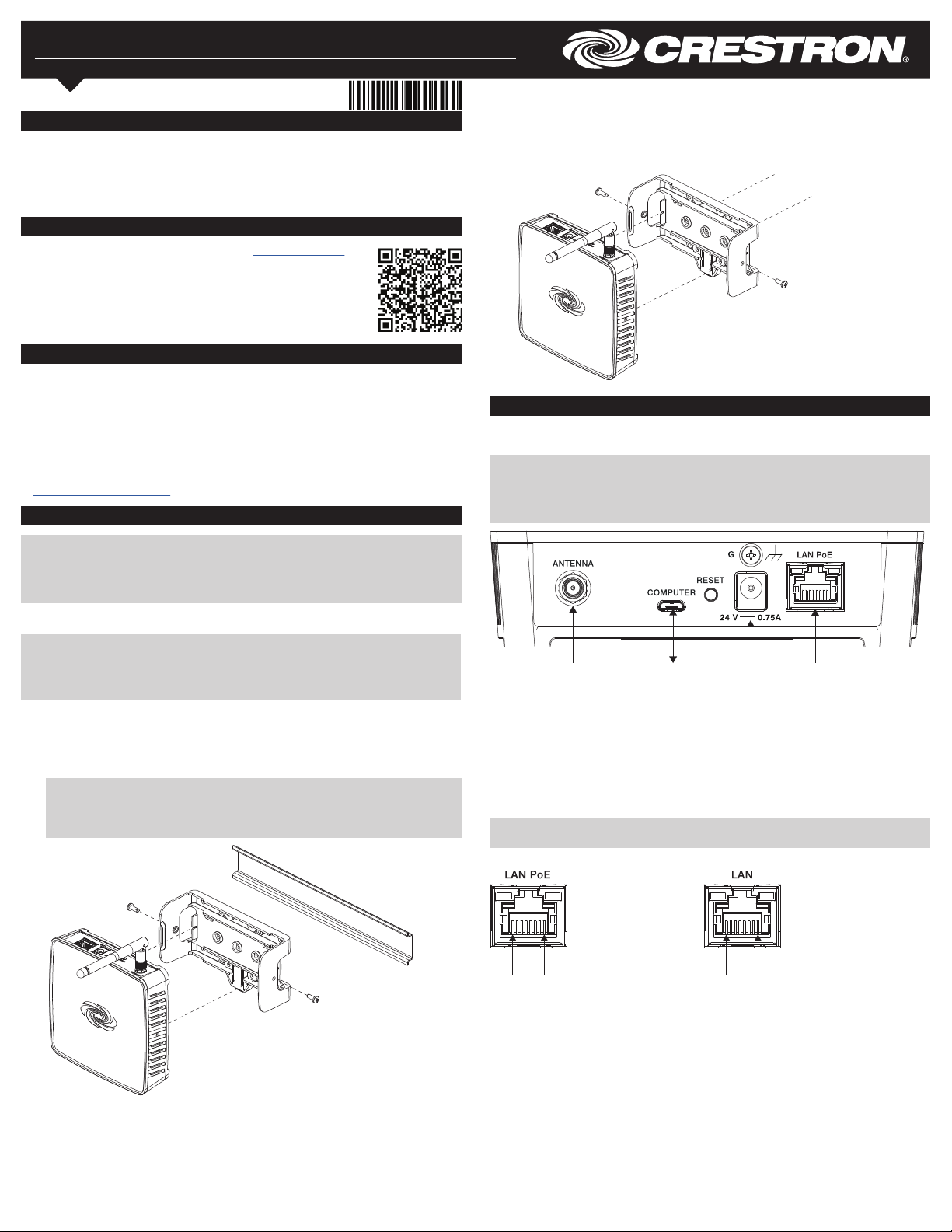
Vertical Flat Surface Mounting
1. Attach the bracket to the wall (wall mount screws not included).
2. Attach the ZUMNET-GATEWAY to the bracket by snapping it into place.
3. Insert the supplied screws through the side of the bracket and secure the gateway.
Make Connections
Make the necessary connections as called out in the illustrations that follow. Apply power
after all connections have been made.
NOTE: When making connections to the ZUMNET-GATEWAY, use Crestron power
supplies for Crestron equipment.
NOTE: The antenna must be attached directly to the antenna connector. It can be
extended with an optional ANT-EXT-10 Antenna Extender (sold separately).
For
included
antenna
To supply power using a Crestron PoE injector (sold separately), do the following.
1. Attach the supplied ac power cord to the IEC 320 connector on the PoE (Power over
Ethernet) injector.
2. Use a CAT5 cable to connect the LAN port of the PoE injector to the LAN.
3. Use a CAT5 cable to connect the LAN POE port of the PoE injector to the LAN PoE
input port of the ZUMNET-GATEWAY.
4. Insert the other end of the power cord into an active ac outlet.
NOTE: In the listing of LAN PoE and LAN pins in the following image, arrows denote
internal pin connections.
LAN PoE and LAN Pin Assignments
LAN PoE Pins
1. Data Pair 1
2. Data Pair 1
3. Data Pair 2
4. +Vdc
5. +Vdc
6. Data Pair 2
Pin 8 Pin 1
7. -Vdc
8. -Vdc
USB
to
PC
Power
supply
input
Pin 8 Pin 1
LAN
PoE
input
LAN Pins
1. Data Pair 1
2. Data Pair 1
3. Data Pair 2
4. No Connection
5. No Connection
6. Data Pair 2
7. No Connection
8. No Connection
Page 2

Specications
SPECIFICATION DETAILS
Supported Devices
Zūm Net Devices
Maximum Devices Allowed
Wireless Communications
RF Transceiver
Range
Wired Communications
Ethernet
USB
Power
Power over Ethernet (PoE)
Power Pack
Power Consumption
Environmental
Temperature
Humidity
Heat Dissipation
Construction
Enclosure
Mounting
Supports Crestron Zūm Net wireless devices only
up to 100 Zūm Network Bridges per Zūm Net Gateway
Supports
Zūm Net 2-way RF, 2.4 GHz ISM Channels 11-26 (2400 to 2483.5 MHz), default channel 15, IEEE 802.15.4 compliant
50 ft (15 m) to nearest Zūm Net mesh network device(s), subject to site-specic conditions and individual device capabilities,
range between oors or ceilings is limited to one level
10/100 Mbps, auto-switching, auto-negotiating, auto-discovery, full/half duplex, DHCP, IEEE 802.3at Type 1 compliant
USB device port for setup
IEEE 802.3at Type 1 (802.3af compatible) Class 1 (3.84 W) PoE powered device;
Maximum distance is 100 meters (328 feet)
0.75 A (minimum) @ 24 VDC;
100-240 VAC, 50/60 Hz power pack,
model PW-2407WU not included
2.1 watts typical
41° to 104 °F (5° to 40 °C)
10% to 90% RH (non-condensing)
7 Btu/h
IFE small form factor, black and blue plastic
Freestanding, surface mount, or 35 mm DIN EN 60715 rail mount;
Occupies 8 DIN module spaces (144 mm); Surface/DIN rail mounting bracket included, optional rack mount and pole mount
kits not included
NOTE: “Zūm Net” refers to the wireless mesh network that connects one or more rooms with a Zūm Floor Hub, and consists of one Zūm Net Wireless Gateway and one or more Zūm
Network Bridges. Each Zūm Network Bridge functions as a routing node, which relays the signals it receives on to any other Zūm Net devices within range. This effectively extends the
total range of the network and provides multiple redundant signal paths for extra reliability. A maximum of six “hops” across routing nodes is allowed, although a maximum of three is
recommended. Up to 100 Zūm Net devices are permitted per gateway, although best practices suggest a limit of 50. Refer to the “Installation and Setup of Crestron RF Products” Best
Practices guide (Doc. 6689) at www.crestron.com/manuals for more information.
NOTE: Do not stack multiple gateways.
This product is Listed to applicable UL® Standards and requirements by Underwriters Laboratories
Inc.
Federal Communications Commission (FCC) Compliance Statement
This device complies with part 15 of the FCC Rules. Operation is subject to the following conditions:
(1) This device may not cause harmful interference and (2) this device must accept any interference
received, including interference that may cause undesired operation.
CAUTION: Changes or modications not expressly approved by the manufacturer responsible for
compliance could void the user’s authority to operate the equipment.
NOTE: This equipment has been tested and found to comply with the limits for a Class B digital
device, pursuant to part 15 of the FCC Rules. These limits are designed to provide reasonable
protection against harmful interference in a residential installation. This equipment generates, uses,
and can radiate radio frequency energy and, if not installed and used in accordance with the
instructions, may cause harmful interference to radio communications. However, there is no guarantee
that interference will not occur in a particular installation.
If this equipment does cause harmful interference to radio or television reception, which can be
determined by turning the equipment off and on, the user is encouraged to try to correct the
interference by one or more of the following measures:
• Reorient or relocate the receiving antenna.
• Increase the separation between the equipment and receiver.
• Connect the equipment into an outlet on a circuit different from that to which the receiver is
connected.
• Consult the dealer or an experienced radio/TV technician for help.
Industry Canada (IC) Compliance Statement
This device complies with Industry Canada license-exempt RSS standard(s). Operation is subject to
the following two conditions: (1) this device may not cause interference and (2) this device must
accept any interference, including interference that may cause undesired operation of the device radio
interference to other users, the antenna type and its gain should be so chosen that the equivalent
isotropically radiated power (e.i.r.p.) is not more than that necessary for successful communication.
Industrie Canada (IC) Déclaration de conformité
Le présent appareil est conforme aux CNR d’Industrie Canada applicables aux appareils radio
exempts de licence. L’exploitation est autorisée aux deux conditions suivantes : (1) l’appareil ne doit
pasproduire de brouillage, et (2) l’utilisateur de l’appareil doit accepter tout brouillage radioélectrique
subi, même si le brouillage est susceptible d’en compromettre le fonctionnement.
Conformément à la réglementation d’Industrie Canada, le présent émetteur radio peut fonctionner
avec une antenne d’un type et d’un gain maximal (ou inférieur) approuvé pour l’émetteur par Industrie
Canada. Dans le but de réduire les risques de brouillage radioélectrique à l’intention des autres
utilisateurs, il faut choisir le type d’antenne et son gain de sorte que la puissance isotrope rayonnée
équivalente (p.i.r.e.) ne dépasse pas l’intensité nécessaire à l’établissement d’une communication
satisfaisante.
To satisfy RF exposure requirements, this device and its antenna must operate with a separation
distance of at least 20 centimeters from all persona and must not be colocated in conjunction with any
other antenna or transmitter.
The product warranty can be found at www.crestron.com/warranty.
The specic patents that cover Crestron products are listed at www.crestron.com/legal/patents.
Certain Crestron products contain open source software. For specic information, please visit
www.crestron.com/opensource.
Crestron, the Crestron logo, inNET EX, and Zūm are either trademarks or registered trademarks of
Crestron Electronics, Inc. in the United States and/or other countries. Bluetooth is either a trademark
or registered trademark of Bluetooth SIG, Inc. in the United States and/or other countries. UL and the
UL logo are either trademarks or registered trademarks of Underwriters Laboratories, Inc. in the
United States and/or other countries. Wi-Fi is either a trademark or registered trademark of Wi-Fi
Alliance in the United States and/or other countries. Other trademarks, registered trademarks, and
trade names may be used in this document to refer to either the entities claiming the marks and
names or their products. Crestron disclaims any proprietary interest in the marks and names of others.
Crestron is not responsible for errors in typography or photography.
This document was written by the Technical Publications department at Crestron.
©2018 Crestron Electronics, Inc.
Crestron Electronics, Inc. Installation Guide - DOC. 7936C
15 Volvo Drive, Rockleigh, NJ 07647 (2048522)
Tel: 888.CRESTRON 06.18
Fax: 201.767.7576 Specications subject to
www.crestron.com change without notice.
 Loading...