

Page 1

Zūm™ Light Control System
TEST
SETUP
SETUP
Press and hold until LED lights
Press 3x
then
TEST
SETUP
SETUP
TEST
SETUP
TEST
SETUP
TEST
SETUP
Setup Guide
How to Set Up a Zūm Space and Add Zūm Devices
Once all devices are physically installed in a board room or conference space, a new
Zūm space can be created and devices added.
NOTE: Only set up one Zūm space at a time.
NOTE: For simplified setup of a Zūm space, use the Zūm app on a mobile device.
Step 1 Create a New Zūm Space
Creating a Zūm space defines the area where the devices are located, such as a board
room or conference room. A Zūm space is created with a keypad, dimmer or switch, a
J-box device, or an AV Bridge.
NOTE: Creating a Zūm space can only be performed by one device in the space.
NOTE: A Zūm space cannot be created from a battery-powered keypad.
To create a new Zūm space using a keypad, dimmer, or switch:
1. Press the bottom button 5 times.
2. Press and hold the button until the LED on the device lights (about 10 seconds).
After approximately 3 seconds, the device LED begins slowly flashing. This
indicates that the Zūm space is now created and in Joining mode, allowing you
to add devices.
Press 5x
Press and hold until LED lights
then
To create a new Zūm space using a J-box device or an AV Bridge:
1. Press the Setup button 5 times.
2. Press and hold the Setup button until the LED on the device lights (about
10 seconds). After approximately 3 seconds, the device LED begins slowly
flashing. This indicates that the Zūm space is now created and in Joining mode,
allowing you to add devices.
SETUP
TEST
SETUP
TX
PWR
RX
NET
ERR
Press 5x
Press 5x
then
Press and hold until LED lights
then
Press and hold until LED lights
NOTE: The device that is used to create the Zūm space is automatically added to
the space and does not need to be added in Step 2.
Step 2 Add Zūm Devices to the Zūm Space
After a new Zūm space is created, add Zūm devices while the space is in Joining mode.
NOTE: A battery-powered device does not flash its LED after joining the space.
This is to conserve battery power. The non-battery-powered devices in the space
will flash their LED to indicate that the space is in Joining mode.
NOTE: A Zūm mesh device can belong to only one space.
NOTE: Joining mode ends automatically after 4 minutes.
Add a keypad, dimmer, or switch to a Zūm space:
1. Press the top button 3 times.
2. Press and hold the button until the LED on the device lights (up to 10 seconds).
The LED on the device will start to flash slowly to indicate that it has joined the
space.
Add a J-box device or AV Bridge to a Zūm space:
1. Press the Setup button 3 times.
2. Press and hold the Setup button until the LED on the device lights (up to
10 seconds). The LED on the device will start to flash slowly to indicate that it has
joined the space.
SETUP
TEST
SETUP
TX
PWR
RX
NET
ERR
Press 3x
Press 3x
then
Press and hold until LED lights
then
Press and hold until LED lights
NOTE: Only one ZUMMESH-AVBRIDGE can be installed per Zūm space.
Add a photocell or occupancy/vacancy sensor to a Zūm space:
1. Press the setup button 3 times.
2. Press and hold the button until the LED on the device lights (up to 10 seconds) to
indicate that it has joined the space.
Press 3x
Press 3x
then
Press and hold until LED lights
then
Press and hold until LED lights
Step 3 Complete Zūm Space Setup
To finish creating a Zūm space, press any button on a device that is part of the Zūm
space to exit Joining mode.
Add a Zūm Device to an Existing Zūm Space
Add new Zūm devices to an existing Zūm space by placing the Zūm space in Joining
mode.
Add the Zūm device using a keypad, dimmer, or switch:
1. Enter Joining mode.
a. Press and hold both the top and bottom buttons until the LED lights (about
5 seconds).
b. Press the top button once.
c. Press the bottom button once. The LEDs on all devices in the space (except
battery powered devices) flash slowly to indicate that the devices are part of
the space and that the space is in Joining mode.
Press and hold until LED lights
then then
Press and hold until LED lights
2. Add the Zum device according to “Step 2 Add Zūm Devices to the Zūm Space.”
3. Press any button on a device that is part of the Zūm space to exit Joining mode.
Press 1x
Press 1x
Add the Zūm device using a J-box device:
1. Enter Joining mode.
a. Press the SETUP button 2 times.
b. Press the TEST button once. The LEDs on all devices in the space (except
battery powered devices) flash slowly to indicate that the devices are part of
the space and that the space is in Joining mode.
SETUP
TEST
Press SETUP 2x
then
Press TEST 1x
2. Add the Zum device according to “Step 2 Add Zūm Devices to the Zūm Space.”
3. Press any button on a device that is part of the Zūm space to exit Joining mode.
Connect the Network Bridge to the Zūm Net Wireless Gateway
The Zūm Network Bridge connects wirelessly to the Zūm Net Wireless Gateway to form
a centrally managed, enterprise-wide lighting control system.
Add the Zūm Network Bridge to the Zūm Net Wireless Gateway’s network:
1. Press the ACQUIRE button on the Zūm Net Wireless Gateway to place the
gateway into Acquire mode.
2. Join the Zūm Net Wireless Gateway’s network.
a. Press the SET button on the Network Bridge 3 times.
b. Press and hold the SET button until the LED flashes once (up to 10 seconds).
The LED on the Network Bridge slowly flashes to indicate that it is searching
for a network to join.
• The LED lights for 5 seconds when the network bridge successfully joins the
gateway.
• The LED flashes fast to indicate that the network bridge failed to join the
gateway. Press the SET button to acknowledge the failure and then repeat
this procedure.
Press 3x
Press and hold until LED lights
then
3. Press the ACQUIRE button on the gateway to exit Acquire mode.
Calibrate and Test the Daylight Sensor
To enable daylight harvesting, calibrate and then test the daylight sensor after all
devices are installed and powered in the Zūm space.
NOTE: When setting up the daylight sensor, consider the following:
• Only dimmers are capable of adjusting load levels that are driven by daylight
sensor readings.
• Daylighting only operates when Scene 1 is enabled.
• Calibrate the daylight sensor during the day when the sun is bright. Avoid
light fluctuations caused by clouds that are rapidly exposing and hiding the
sun.
• Do not stand between the daylight sensor and the windows. Doing so affects
the readings and can result in poor calibration settings.
Calibrate the Daylight Sensor:
1. Adjust the lights in the room to the desired levels.
NOTE: Take the natural daylight levels into consideration when setting the
load levels. Each dimmer can be set to a different level. Typically, lights closer
to windows are dimmed more than lights away from windows.
NOTE: To prevent daylighting from affecting a dimmer, set the lights on the
dimmer to brighter than scene 1.
2. Press and hold the button for 5 seconds to initiate the daylight calibration
process. The LED flashes red to indicate that the calibration process is in progress;
this process takes 60 seconds. During the calibration process, the lights cycle on
and off. After the daylight calibration process is complete, the room enters Test
mode. Refer to “Test Mode” for details.
Test Mode
Test mode is used to verify that the settings stored during calibration are correct.
Changes to the amount of light in the space results in rapid light level adjustments.
NOTE: During normal operation, the light levels are adjusted slowly so that they
are not seen by the occupants in the room.
To enter Test mode, press and hold the button for 2 seconds. When in Test mode, the
LED flashes twice, pauses, then repeats. The device exits Test mode after 2 minutes.
To verify the daylight sensor settings, close the blinds or block the cover of the sensor
to reduce the amount of light in the space; the light level will increase. Open the blinds
or unblock the cover of the sensor to increase the amount of light in the space; the
light level will decrease.
Press and hold 2 sec.
Configure Keypads to Control Specific Loads
Keypads control all load controllers in the space (this is the default functionality). Use
Binding mode to change the load controllers that are bound (controlled) or not bound
(not controlled) by the keypad.
There are two methods of removing or changing loads that are bound to the keypad:
• Local Binding Configuration: Use when all load controllers are accessible.
• Remote Binding Configuration: Use when a load controller is not accessible.
NOTE: Keypads do not control J-box plug controllers.
NOTE: Binding Mode exits after 5 minutes when initiated from an ac-powered
keypad or 1 minute when initiated from a battery powered keypad.
Local Binding Configuration
Local binding configuration is used when all load controllers in the Zūm space are
accessible (i.e., there are no j-box load controllers in the Zūm space). To change the
load controllers that are bound to the keypad.
1. Enter Binding mode.
a. Press and hold both the top and bottom buttons until the LED lights (about
5 seconds).
b. Press the top button three times.
c. Press the bottom button once. The LED on the keypad flashes three times,
pauses, then repeats.
• The LED flashes fast to indicate that the load controller is bound.
• The LED flashes slow to indicate that the load controller is not bound.
Press and hold until LED lights
then then
Press and hold until LED lights
2. Walk up to all load controllers in the space and press and hold the top button of
the selected load controller until the LED lights (about 7 seconds) to change it to
bound or not bound to the keypad.
• The LED flashes fast to indicate that the load controller is bound.
• The LED flashes slow to indicate that the load controller is not bound.
NOTE: If all load controllers in the Zūm space are assigned as not bound
to the keypad, the keypad will restore its default functionality and all load
controllers will become bound to the keypad.
Press and hold 7 sec.
OR
3. Press the bottom button on the keypad 3 times to exit.
Press 3x
Press 1x
SETUP
TEST
Press and hold 7 sec.
Press and hold 5 sec.
Page 2
Remote Binding Configuration
Remote Binding configuration is used when all load controllers in the Zūm space are
not accessible (i.e., there are j-box load controllers). To change the load controllers
that are bound to the keypad.
1. Enter Binding mode.
a. Press and hold both the top and bottom buttons until the LED lights (about
5 seconds).
b. Press the top button three times.
c. Press the bottom button once. The LED on the keypad flashes three times,
pauses, then repeats.
• The LED flashes fast to indicate that the load controller is bound.
• The LED flashes slow to indicate that the load controller is not bound.
Press and hold until LED lights
Press 3x
then then
Press and hold until LED lights
Press 1x
NOTE: Use the keypad that has been selected for controlling the load to perform
the entire remote linking process.
2. Press and hold the bottom button of the keypad until a set of lights in the space
starts to flash on and off (about 3 seconds). The flashing lights indicate the
selected load controller. The LED on the keypad flashes to indicate that the load
is bound or unbound.
• The LED flashes fast to indicate that the load controller is bound.
• The LED flashes slow to indicate that the load controller is not bound.
NOTE: The flashing rate of the lights does not indicate the link status.
Press and hold 3 sec.
3. Press the bottom button of the keypad repeatedly to cycle through all of the
load controllers in the Zūm space until the desired load starts flashing.
Press 1x
4. Press the top button of the keypad to assign the load controller as bound or not
bound to the keypad. The LED on the keypad flashes to indicate that the load is
bound or unbound.
• The LED flashes fast to indicate that the load controller is bound.
• The LED flashes slow to indicate that the load controller is not bound.
NOTE: If all load controllers in the Zūm space are assigned as not bound
to the keypad, the keypad will restore its default functionality and all load
controllers will become bound to the keypad.
NOTE: The flashing lights indicate the selected load controller, not the
binding status.
Press 1x
5. Repeat steps 3 and 4 until all load controllers are bound or unbound from the
keypad.
6. Press the bottom button on the keypad 3 times to exit.
Change the Default Scenes
The Zūm keypad buttons recall predefined scenes (light levels) that are stored in the
load controllers. The default scenes are ON (scene 1) which sets the loads at 90%,
SCENE 2 which sets the loads at 50%, and SCENE 3 which sets the loads at 10%. Load
controllers can save up to 16 scenes.
There are several methods of changing the default scenes, use the method that
matches your needs.
• End-User Method - Change the light levels for SCENE 2 or SCENE 3 when all load
controllers are easily accessible. ON (scene 1) cannot be changed. This method
cannot be used on 2-button keypads.
• Manual Method - Change the light levels for ON (scene 1) in addition to SCENE 2
or SCENE 3 when all load controllers are easily accessible.
• Remote Method - Change the light levels for ON (scene 1), SCENE 2, or SCENE 3
when a load controller is not physically accessible.
NOTE: A dimmer lowered to 0% will turn the dimmer off when the scene is recalled.
NOTE: A load controller that is not bound to the keypad cannot be part of the scene.
End-User method to change the scene for Scene 2 or Scene 3:
1. Set all load controllers that are bound to the keypad to their desired light level.
2. Press and hold the SCENE 2 or SCENE 3 button until the LED lights (about
5 seconds) to save the light levels to the selected button.
Manual method to change the scene for ON (Scene 1):
NOTE: Scene 2 and Scene 3 can also be changed.
1. Enter Scene Setting Mode using the keypad that will recall the scene.
a. Press and hold both the top and bottom buttons until the LED lights (about
5 seconds).
b. Press the top button two times.
c. Press the bottom button once. The LED on the keypad flashes its LED two
times every two seconds to indicate that it is in Scene Setting mode. Load
controllers that are bound to the keypad flash their LED rapidly.
Press and hold until LED lights
then then
Press and hold until LED lights
NOTE: Scene Setting Mode exits after 5 minutes when initiated from an acpowered keypad or 1 minute when initiated from a battery powered keypad.
2. Adjust all light levels.
• Using a dimmer, press and hold the top button to raise the light level or press
and hold the bottom button to lower the light level.
• Using a switch, Press the top button to turn the lights on or press the bottom
button to turn the lights off.
• Using a J-box load controller, press and hold the TEST button on the J-box
device to cycle-dim the light.
3. Using the keypad that initiated Scene Setting mode, press the ON, SCENE 2, or
SCENE 3 button to save the light levels to the selected scene button.
4. Repeat steps 2 and 3 for each scene button.
5. Press the bottom button on the keypad 3 times to exit.
Press 2x
Press 1x
Remote Method to change the scene for ON (scene 1), SCENE 2, or SCENE 3
1. Enter Scene Setting Mode using the keypad that will recall the scene.
a. Press and hold both the top and bottom buttons until the LED lights (about 5
seconds).
b. Press the top button two times.
c. Press the bottom button once. The LED on the keypad flashes its LED two
times every two seconds. Load controllers that are bound to the keypad flash
their LED rapidly.
Press and hold until LED lights
Press 2x
then then
Press and hold until LED lights
Press 1x
NOTE: Scene Setting Mode exits after 5 minutes when initiated from an acpowered keypad or 1 minute when initiated from a battery powered keypad.
2. Press and hold the bottom button of the keypad until a set of lights in the space
flashes on and off twice (about 3 seconds) to indicate that it is selected load. The
lights return to their previous level.
Press and hold 3 sec.
3. Press the bottom button of the keypad to cycle through all of the load controllers
in the Zūm space until the desired load starts flashing.
Press 1x
4. Adjust the light levels by holding the top button on the keypad to raise the light
level or holding the bottom button on the keypad to lower the light level.
5. Press the ON, SCENE 2, or SCENE 3 button to save the scene.
6. Repeat steps 3 through 5 until all load controllers and all scenes are defined.
7. Press the bottom button on the keypad 3 times to exit.
Factory Reset
Perform a factory reset when the device is removed from the network or to remove
the configuration settings. The device must also be factory reset if the device is being
moved to a different system.
NOTE: New-in-box devices do not need to be factory reset before joining a system.
Factory Reset a Keypad, Dimmer, or Switch
To factory reset a keypad, dimmer, or switch, press and hold the top and bottom
buttons until the LED lights (about 5 seconds), and then release both buttons. Then,
press and hold the bottom button until the LED lights (about 10 seconds).
Factory Reset a J-Box Device
To factory reset a J-box device, press and hold the TEST and SETUP buttons until the
SETUP LED lights (about 10 seconds), and then release both buttons. The SETUP LED
and output turn on.
Factory Reset an Occupancy or Vacancy Sensor
To factory reset an occupancy or vacancy sensor, press and hold the TEST button until
the LED flashes rapidly 3 times (about 10 seconds), then release the button.
Factory Reset a Daylight Sensor
To factory reset the daylight sensor, press and hold the button until the LED flashes
rapidly 3 times (about 10 seconds), then release the button.
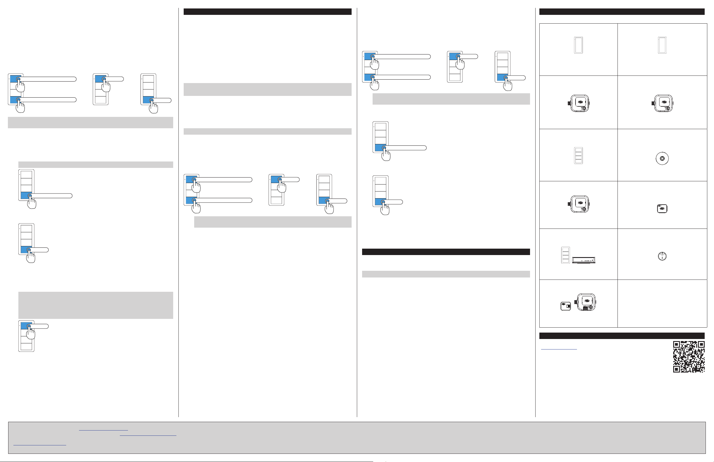
Typical Zūm Space Devices
A typical Zūm space can employ any of the following devices:
Dimmer - Wall Mount
Dimmer to raise and lower the lights.
ZUMMESH-5A-LV
Models:
ZUMMESH-DELV
ZUMMESH-DIM
Dimmer - J-box Mount
Dimmer to raise/lower the lights
(controlled by a keypad).
Models:
ZUMMESH-JBOX-16A-LV
ZUMMESH-JBOX-5A-LV
Keypad
Keypad to control dimmers and
switches.
Models:
Switch to toggle the lights (controlled by a
Models:
occupancy/vacancy. Toggles the lights and
Switch - Wall Mount
Switch to toggle the lights.
ZUMMESH-5A-SW
ZUMMESH-JBOX-20A-SW
Switch - J-box Mount
keypad).
ZUMMESH-5A-SW
ZUMMESH-JBOX-20A-SW
Occupancy or Vacancy Sensor
Ceiling mounted sensor to detect
the plug controller.
Models:
ZUMMESH-KP
ZUMMESH-KPBATT
Plug Controller
Toggles the connected plug receptacle
Models:
ZUMMESH-PIR-OCCUPANCY-BATT
ZUMMESH-PIR-VACANCY-BATT
Network Bridge
Enables setup using the Zūm app and
integrates standalone space with the Zūm
Floor Hub.
Model:
Provides AV equipment control using
ZUMMESH-JBOX-20A-
PLUG
AV Control
RS-232 commands.
Model: ZUMMESH-NETBRIDGE
Daylight Sensor
Detects the light-level in the space and
raises or lowers the lights (daylight
harvesting).
SETUP
TX
PWR
RX
NET
ERR
Model: ZUMMESH-OL-PHOTOCELL-BATT
Models:
ZUMMESH-KPAVBATT
ZUMMESH-AVBRIDGE
Integration Module
Controls third-party devices.
N.O.
COM
N.C.
Models:
ZUMMESH-CCO
ZUMMESH-JBOX-SIM
Additional Resources
Visit the product page on the Crestron website
(www.crestron.com) for additional information and the latest
firmware updates. Use a QR reader application on your mobile
device to scan the QR image.
The product warranty can be found at www.crestron.com/warranty.
The specific patents that cover Crestron products are listed at www.crestron.com/legal/patents.
Certain Crestron products contain open source software. For specific information, please visit
www.crestron.com/opensource.
Crestron, the Crestron logo, and Zūm are either trademarks or registered trademarks of
Crestron Electronics, Inc. in the United States and/or other countries. Other trademarks,
registered trademarks, and trade names may be used in this document to refer to either the
entities claiming the marks and names or their products. Crestron disclaims any proprietary
interest in the marks and names of others. Crestron is not responsible for errors in typography
or photography.
This document was written by the Technical Publications department at Crestron.
©2018 Crestron Electronics, Inc.
Crestron Electronics, Inc. Setup Guide - DOC. 7957B
15 Volvo Drive, Rockleigh, NJ 07647 (2048147)
Tel: 888.CRESTRON 04 .18
Fax: 201.767.7576 Specifications subject to
www.crestron.com change without notice.
 Loading...