

Page 1
TTK-MP/MPC/IPAC & SMK-MP/MPC/IPAC
TableTop and Swivel Mount Kits for MP, MPC, & IPAC
Installation Guide
Description
The Crestron® TTK-MP/MPC/IPAC tabletop kit provides a tabletop enclosure for any
MP series media presentation button panel, MPC and MPC3-302 series media
presentation controller, or IPAC integrated professional automated computer. The
device’s front panel is angled at a xed tilt of 45 degrees when installed in the enclosure.
The complete assembly may be placed on any at, level surface, with the option to install
the assembly to the surface permanently using screws.
The optional SMK-MP/MPC/IPAC swivel mount kit enables the enclosure to be
permanently mounted to a table, desk, or counter top surface, while retaining the ability
to rotate. The swivel range may be customized with optional limiting screws.
The installation procedures for both the TTK-MP/MPC/IPAC and SMK-MP/MPC/IPAC
are covered in this guide.
Additional Resources
Visit the product pages on the Crestron
website (www.crestron.com) for additional
information and the latest rmware updates.
Use a QR reader application on your mobile
device to scan the QR images.
TTK-MP/MPC/IPAC
SMK-MP/MPC/IPAC
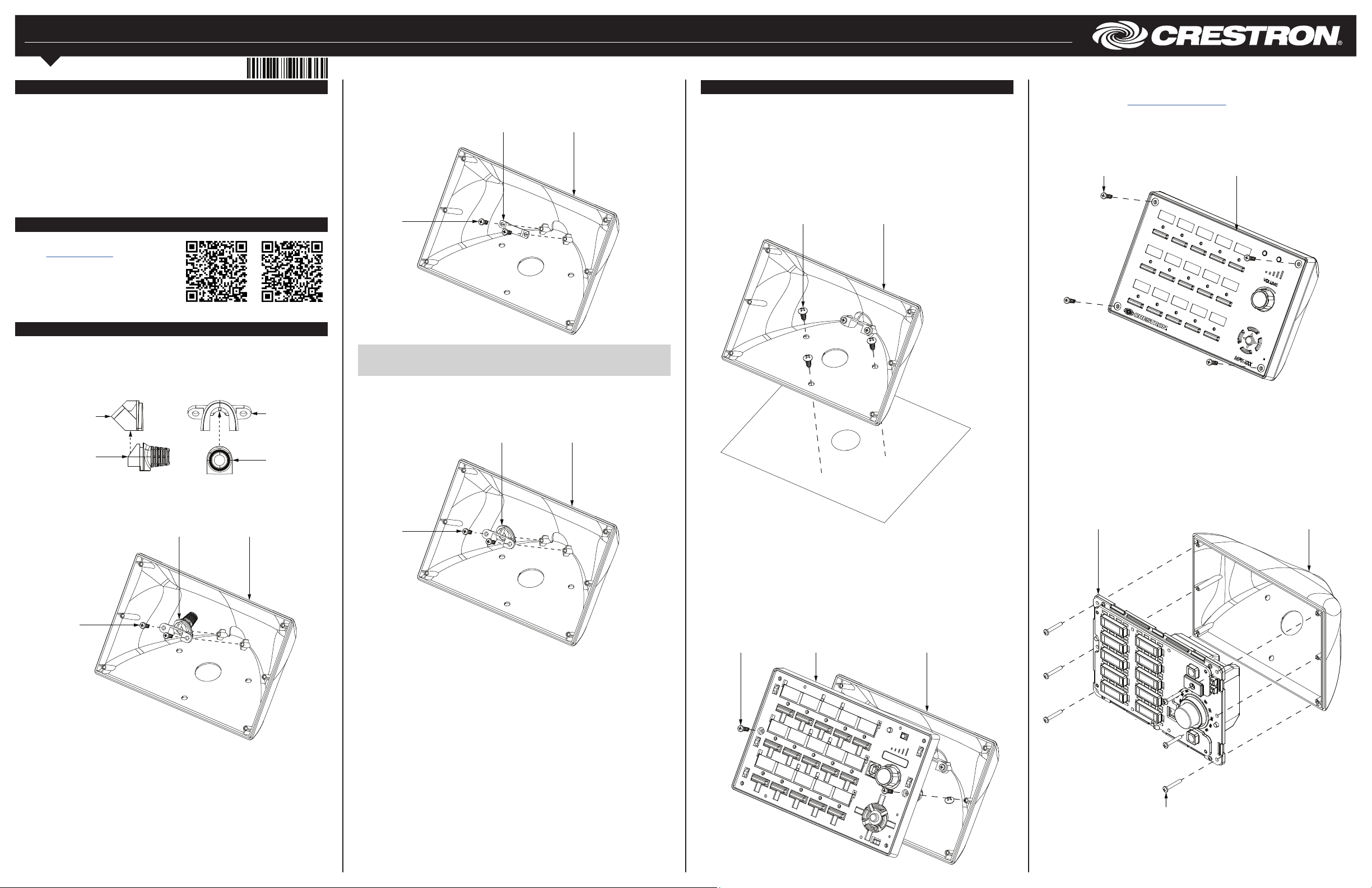
Prepare the TTK-MP/MPC/IPAC
The TTK-MP/MPC/IPAC provides two options for routing cables through the rear of the
enclosure and one option for routing cables through the bottom of the enclosure.
To route a single cable through the rear of the enclosure:
1. Join the plug insert (open rear) and rubber cable grommet.
Joining the Plug Insert and Cable Grommet
Plug insert
(side view)
Cable grommet
(side view)
2. Attach the joined assembly to the TTK-MP/MPC/IPAC with the two 4-20 x 1/2"
screws.
Attaching the Assembly to the TTK-MP/MPC/IPAC
Joined
assembly
Screw (2):
4-20 x 1/2"
TTK-MP/MPC/IPAC
enclosure
Plug insert
(rear view)
Cable grommet
(rear view)
To route multiple cables through the rear of the enclosure, attach the wire capture to the
TTK-MP/MPC/IPAC with the two included 4-20 x 1/2" screws.
Attaching the Wire Capture to the TTK-MP/MPC/IPAC
Wire
capture
Screw (2):
4-20 x 1/2"
NOTE: The illustration above shows the metal wire capture installed “bow” side up.
When fewer cables are routed through the rear of the TTK-MP/MPC/IPAC, install the
metal wire capture “bow” side down to better secure the cables.
To route one or more cables through the bottom of the enclosure, attach the plug insert
(closed rear) to the TTK-MP/MPC/IPAC with the two 4-20 x 1/2" screws.
Attaching the Plug Insert (Closed Rear) to the TTK-MP/MPC/IPAC
Plug insert
(closed rear)
Screw (2):
4-20 x 1/2"
TTK-MP/MPC/IPAC
enclosure
TTK-MP/MPC/IPAC
enclosure
Install the TTK-MP/MPC/IPAC
Attach the TTK-MP/MPC/IPAC to a Flat Surface
To permanently attach the TTK-MP/MPC/IPAC to a table top or other at surface:
1. If routing cables through the bottom of the TTK-MP/MPC/IPAC, cut an
appropriately sized hole in the surface using the hole in the bottom of the
TTK-MP/MPC/IPAC as a guide.
2. Use the three 8-16 x 1/2" screws to attach the TTK-MP/MPC/IPAC to the surface.
Ensure that the hole in the table is aligned with the hole on the bottom of the
TTK-MP/MPC/IPAC.
Attaching the TTK-MP/MPC/IPAC to a Flat Surface
Screw (3):
8-16 x 1/2"
Install an MP/MPC/IPAC Device into the TTK-MP/MPC/IPAC
To install an MP, MPC, or IPAC device into the TTK-MP/MPC/IPAC:
1. If the device’s front panel is still attached, remove the four 4-40 x 1/2" screws
holding the panel in place, and then detach the panel from the device assembly.
2. Route all necessary cables through the bottom or rear of the TTK-MP/MPC/IPAC,
and connect them to the rear of the assembly.
3. Insert two of the six 4-20 x 3/4" screws into the center screw holes on either side
of the assembly, and attach the assembly to the TTK-MP/MPC/IPAC.
Attaching the Assembly to the TTK-MP/MPC/IPAC
Screw (2):
4-20 x 3/4"
MP/MPC/IPAC
assembly
TTK-MP/MPC/IPAC
enclosure
TTK-MP/MPC/IPAC
enclosure
4. If necessary, attach or replace the button holders and button labels on the
assembly. For more information refer to the MP, MPC, or IPAC device’s
documentation at www.crestron.com/manuals.
5. Place the front panel back on the assembly.
6. Insert the four remaining 4-20 x 3/4" screws into the corner screw holes on either
side of the front panel, and secure the device to the TTK-MP/MPC/IPAC.
Attaching the Front Panel to the Assembly
Screw (4):
4-20 x 3/4"
Install an MPC3-302 Device into the TTK-MP/MPC/IPAC
To install an MPC3-302 device into the TTK-MP/MPC/IPAC:
1. If the device’s front panel is still attached, grasp both sides of the panel from the
bottom, and pull upward rmly until the bottom half of the panel detaches from the
assembly. Then, pull the top half of the panel upward rmly until it detaches from
the assembly.
2. Route all necessary cables through the bottom or rear of the TTK-MP/MPC/IPAC,
and connect them to the rear of the assembly.
3. Insert the six 4-20 x 3/4" screws included with the MPC3-302 into the screw holes
on either side of the assembly, and attach the assembly to the TTK-MP/MPC/IPAC.
Attaching the Assembly to the TTK-MP/MPC/IPAC
MPC3-302
assembly
MP/MPC/IPAC
front panel
TTK-MP/MPC/IPAC
enclosure
Screw (6):
4-20 x 3/4"
Page 2
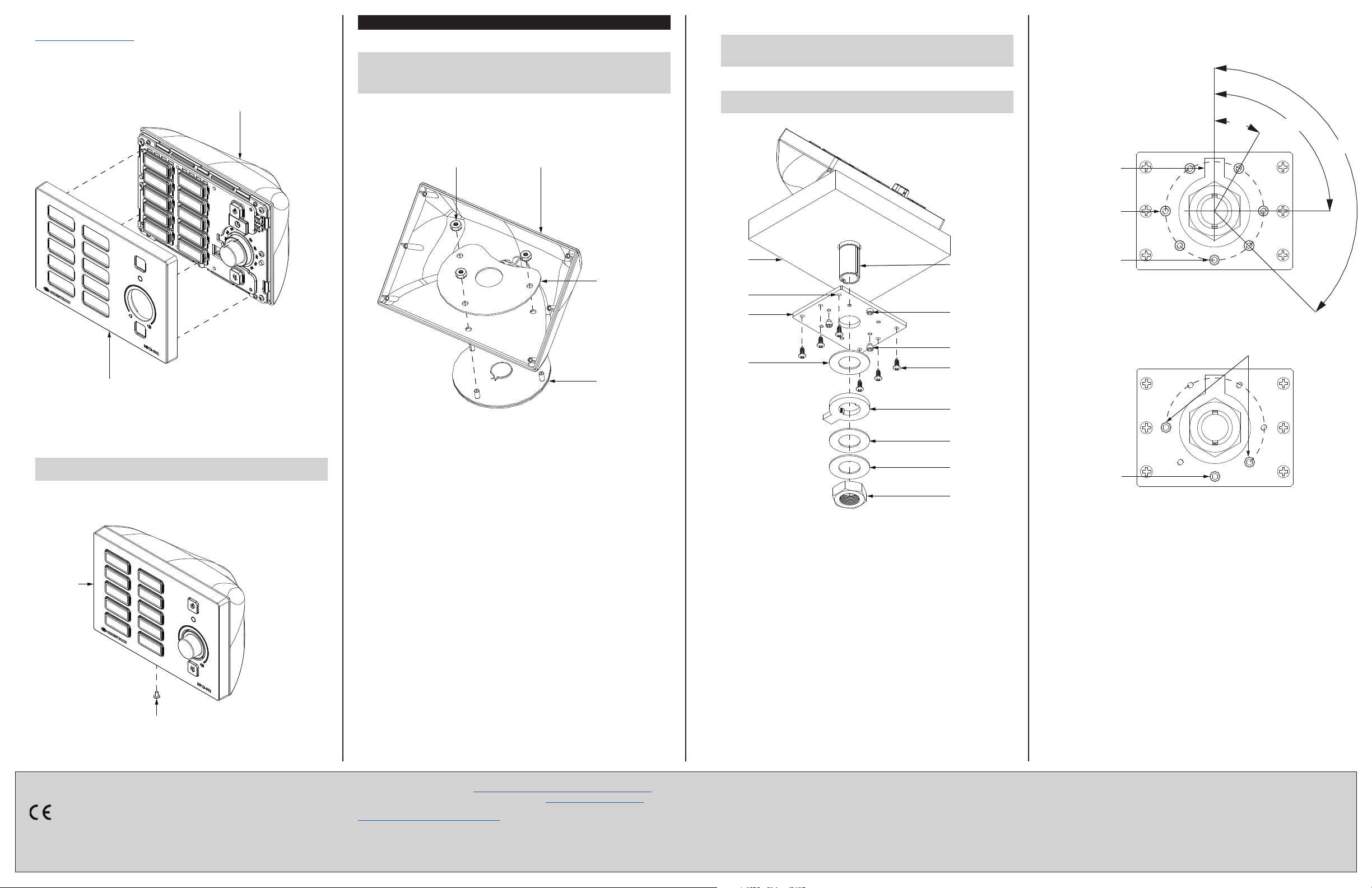
4. If necessary, attach or replace the buttons and the button labels on the assembly.
For more information, refer to the MPC3-302 DO Guide (Doc. 8249) at
www.crestron.com/manuals.
5. Align the front panel with the assembly so that all of the buttons align with their
respective openings in the panel.
6. Press the front panel into the assembly until the panel snaps into place.
Attaching the Front Panel to the Assembly
MPC3-302 assembly
(in enclosure)
Install the SMK-MP/MPC/IPAC
Assemble the Swivel Mount
NOTE: If the SMK-MP/MPC/IPAC is being added to an existing TTK-MP/MPC/IPAC
installation, remove the device’s front panel and assembly from the
TTK-MP/MPC/IPAC enclosure, and then remove the three 8-16 x 1/2" screws securing
the enclosure to the surface.
To assemble the swivel mount:
1. Attach the top of the swivel mechanism tube to the bottom of the
TTK-MP/MPC/IPAC enclosure with the metal top plate and the three 8-32 nuts.
Attaching the Swivel Mechanism Tube
Nut (3):
8-32
TTK-MP/MPC/IPAC
enclosure
6. Slide the provided hardware up onto the swivel tube in the order shown in the
illustration following step 7.
NOTE: The keyed metal washer ts onto the swivel tube in one of two
orientations. Orient the tab on the washer to face away from the permanently
installed limiting screw in the swivel stop plate.
7. Tighten and adjust the 7/8"-14 nut onto the swivel tube to achieve the desired
resistance in swivel assembly motion.
NOTE: A at tool (such as a large at head screwdriver) may be placed in the
slot on the bottom of the swivel tube to hold the tube still while tightening the nut.
Completing the Swivel Mount Assembly
Customize the Swivel Range
Aside from the permanently installed limiting screw that is attached to the swivel stop
plate, two additional 8-32 x 1/8" limiting screws can be attached to the swivel mount
plate to set a custom range for swivel movement. Refer to the illustrations below.
Limiting Screw Locations in Swivel Stop Plate
30°
90°
135
Tab of keyed metal
washer where swivel
motion begins
Locations (6)
for additional
limiting screws
°
MPC3-302
front panel
6. Test the buttons to ensure that they can be pressed and released without
becoming impeded by the front panel, and test the volume knob by rotating it
gently. If any buttons are impeded or if the knob does not rotate easily, remove the
panel as described in step 1, adjust the button and front panel placement, and then
reattach the front panel.
CAUTION: Do not apply force when rotating the knob, and do not attempt to
pull the knob away from the assembly.
®
7. Using the drill bit included with the MPC3-302, screw the Torx
security screw
included with the MPC3-302 into the screw hole on the bottom of the front panel to
secure the panel to the assembly.
Attaching the Security Screw
MPC3-302
front panel
Metal top
plate
Swivel
mechanism
tube (top)
2. If cables are to be routed through the bottom of the TTK-MP/MPC/IPAC, feed the
full length of the cables through the swivel mechanism tube.
3. Prepare the mounting surface using the cutout template provided with the
SMK-MP/MPC/IPAC:
a. Ensure that the center hole diameter for the swivel mount is 7/8" minimum
(22 mm), 15/16" maximum (24 mm).
b. Position the template so that the edge indicated as the front end of the surface
aligns with the front position of the TTK-MP/MPC/IPAC.
c. Observe the dashed line indicating the front edge of the TTK-MP/MPC/IPAC to
ensure that the device does not overhang the mounting surface.
4. Using the six mounting holes on the swivel stop plate as a template, drill pilot holes
0.09" (2 mm) minimum, 0.12" (3 mm) maximum, and no deeper than 0.35" (9 mm)
in the bottom of the mounting surface.
5. Attach the swivel stop plate to the bottom of the mounting surface with the six
8-8B x 1/2" screws, then pass the swivel tube down through the mounting hole
and stop plate. Refer to the illustration following step 7.
Table
(bottom)
Mounting
holes (6)
Swivel stop
plate
Cork/rubber
washer
Swivel
mechanism
tube
Limiting
screw
Screw (2):
8-32 x 1/8"
Screw (6):
8-8B x 1/2"
Keyed metal
washer
Rubber
washer
Flat steel
washer
Nut: 7/8"-14
Permanent
limiting screw
Swivel Stop Plate with Additional Limiting Screws
8-32 x 1/8" limiting screws (2)
limit swivel to custom range
Permanent
limiting screw
Torx® security
screw
As of the date of manufacture, the product has been tested and found to comply with
specications for CE marking.
The product warranty can be found at www.crestron.com/legal/sales-terms-conditions-warranties.
The specic patents that cover Crestron products are listed at www.crestron.com/legal/patents.
Certain Crestron products contain open source software. For specic information, please visit
www.crestron.com/legal/open-source-software.
Crestron and the Crestron logo are either trademarks or registered trademarks of Crestron Electronics,
Inc. in the United States and/or other countries. Torx is either a trademark or a registered trademark of
Acument Intellectual Properties, LLC, in the United States and/or other countries. Other trademarks,
registered trademarks, and trade names may be used in this document to refer to either the entities
claiming the marks and names or their products. Crestron disclaims any proprietary interest in the
marks and names of others. Crestron is not responsible for errors in typography or photography.
This document was written by the Technical Publications department at Crestron.
©2018 Crestron Electronics, Inc.
Crestron Electronics, Inc. Installation Guide - DOC. 6782D
15 Volvo Drive, Rockleigh, NJ 07647 (2023116)
Tel: 888.CRESTRON 03.18
Fax: 201.767.7576 Specications subject to
www.crestron.com change without notice.
 Loading...