

Page 1
cable until the TSW-560 is
2-gang European
Touch
Security
TSW-560/TSW-760/TSW-1060
5 in., 7 in., and 10.1 in. Touch Screens
The Crestron® TSW-560, TSW-760, and TSW-1060 are st ylish and
versatile wall mount touch screens. The touch screen features
onboard voice recognition, web browsing, Smart Graphics® software
technology, H.264 streaming video, a built-in camera, a Rava® SIP
intercom, and PoE+ (Power over Ethernet+) network power. The touch
screen also provides various built-in applications for room scheduling,
conferencing, and home control.
NOTE: Voice recognition, the built-in camera, and the Rava SIP
intercom are not available on the TSW-560-NC, TSW-760-NC, and
TSW-1060-NC models.
The Crestron TSW-560, TSW-760, and TSW-1060 are functionally
similar. For simplicity within this guide, the term “touch screen” is used
except where noted.
Check the Box
Item Qty
TSW-560, TSW-760, or TSW-1060* 1
Latch, Security (P/N 4525305) 1
TSW-560 Only
Bracket, Preconstruction (P/N 4524592) 1
Bracket, Universal Mounting (P/N 4525127) 1
TSW-760 or TSW-1060 Only
Bracket, Mounting (P/N 4525352) 1
Screw, 6-32 x 3/4 in., Undercut Head, Phillips (P/N 2033247) 4
Screw, M3 x 16 mm, Flat Head, Phillips (P/N 2013788) 4
Screw, M3.5 x 25 mm, Flat Head, Phillips (P/N 2023756) 2
* Refer to the TSW-560-B-S, TSW-760-B-S, and TSW-1060-B-S product page
at www.crestron.com for a complete list of color and texture variations.
Install the TSW-560 Mounting Bracket
The TSW-560 can be mounted into drywall and other surfaces, or it
can be mounted onto a wall stud. When mounted into drywall and
other surfaces, the touch screen protrudes 1/2 in. (13 mm) from the
mounting surface.
To install the TSW-560 mounting bracket in preconstruction
applications, use standard drywall nails or screws (not included) to
attach the included TSW-UMB-60-PMK preconstruction mounting
bracket to a wall stud.
TSW-UMB-60-PMK
Use a tie wrap to hold the
mounted.
NOTE: Allow an air gap of at least 12 in. (305 mm) in the wall cavity
above and below the TSW-560 for heat dissipation.
To install the TSW-560 mounting bracket in postconstruction
applications:
1. Use the TSW-UMB-60-PMK as a cutout template by turning
the bracket to face the wall, ensuring it is level, and temporarily
tacking it to the wall with finishing nails (not included) through
the smaller holes around the cutout opening.
2. Trace the cutout opening with an appropriate drywall saw.
TSW-UMB-60
3. Loosen the two screws on the included TSW-UMB-60 universal
mounting bracket.
4. Install the TSW-UMB-60, bottom side first, into the opening.
Push the top surface
downward to install
the bottom half first.
Loosen both
of the screws.
TSW-UMB-60
(side view)
5. Push the rear half of the mounting bracket back so that it is
seated behind the mounting surface completely.
6. Ensure the front of the TSW-UMB-60 is level, and then tighten
the two bracket screws to complete the installation.
CAUTION: To avoid damaging the bracket, do not overtighten
the screws.
Push the rear half back.
Ensure the front is level, and
then tighten both screws.
Install the TSW-760/TSW-1060 Mounting
Bracket
The TSW-760 and TSW-1060 install over a standard 2-gang or 3-gang
U.S. electrical box, a 2-gang European electrical box, or a 2-gang U.K.
electrical box. The touch screen may also be installed into wooden
paneling or furniture with a 2-1/5 in. (56 mm) high by 3-3/4 in. (96 mm)
wide rectangular cutout. When installed, the touch screen protrudes
1/2 in. (13 mm) from the mounting surface, leaving no visible screws.
NOTES:
• Additional mounting options are possible by using the
TSW-UMB-60 universal mounting bracket, the
TSW-UMB-60-PMK preconstruction mounting kit, the
TSW-UMB-60-BBI back box, or the TSW-760/1060-MSMK
multisurface mount kit. For more information, refer to the
product pages on the Crestron website.
• Installing the mounting bracket to an electrical box is required
only if one of the mounting solutions above is not used. For more
information, refer to the mounting solution documentation at
www.crestron.com/manuals.
To mount the touch screen into an electrical box, use the appropriate
screws (four 6-32 x 3/4 in. screws, four M3 x 16 mm screws, or two
M3.5 x 25 mm screws) to attach the mounting bracket to the electrical
box as shown in the following illustrations.
NOTE: For U.S.-style installations, use a #2 Phillips screwdriver. For
European or U.K.-style installations, use a #1 Phillips screwdriver or its
equivalent.
• For U.S.-style installations, use the four 6-32 x 3/4 in. screws.
2-gang U.S.
Screws (4):
6-32 x 3/4 in.
electrical box
Mounting
bracket
• For European-style installations, use the four M3 x 16 mm
screws.
Screws (4):
M3 x 16 mm
electrical box
Mounting
bracket
• For U.K.-style installations (not pictured), use the two M3.5 x 25
mm screws to attach the mounting bracket to the electrical box.
Insert the screws through the center openings in the left and
right sides of the mounting bracket.
Install the Security Latch (Optional)
The included security latch may be attached to the touch screen so
that it cannot be easily removed from the mounting bracket after
installation.
To install the security latch, use a small Phillips screwdriver to screw
the security latch to the top of the touch screen rear housing before
the touch screen is inserted into the mounting bracket.
latch
screen
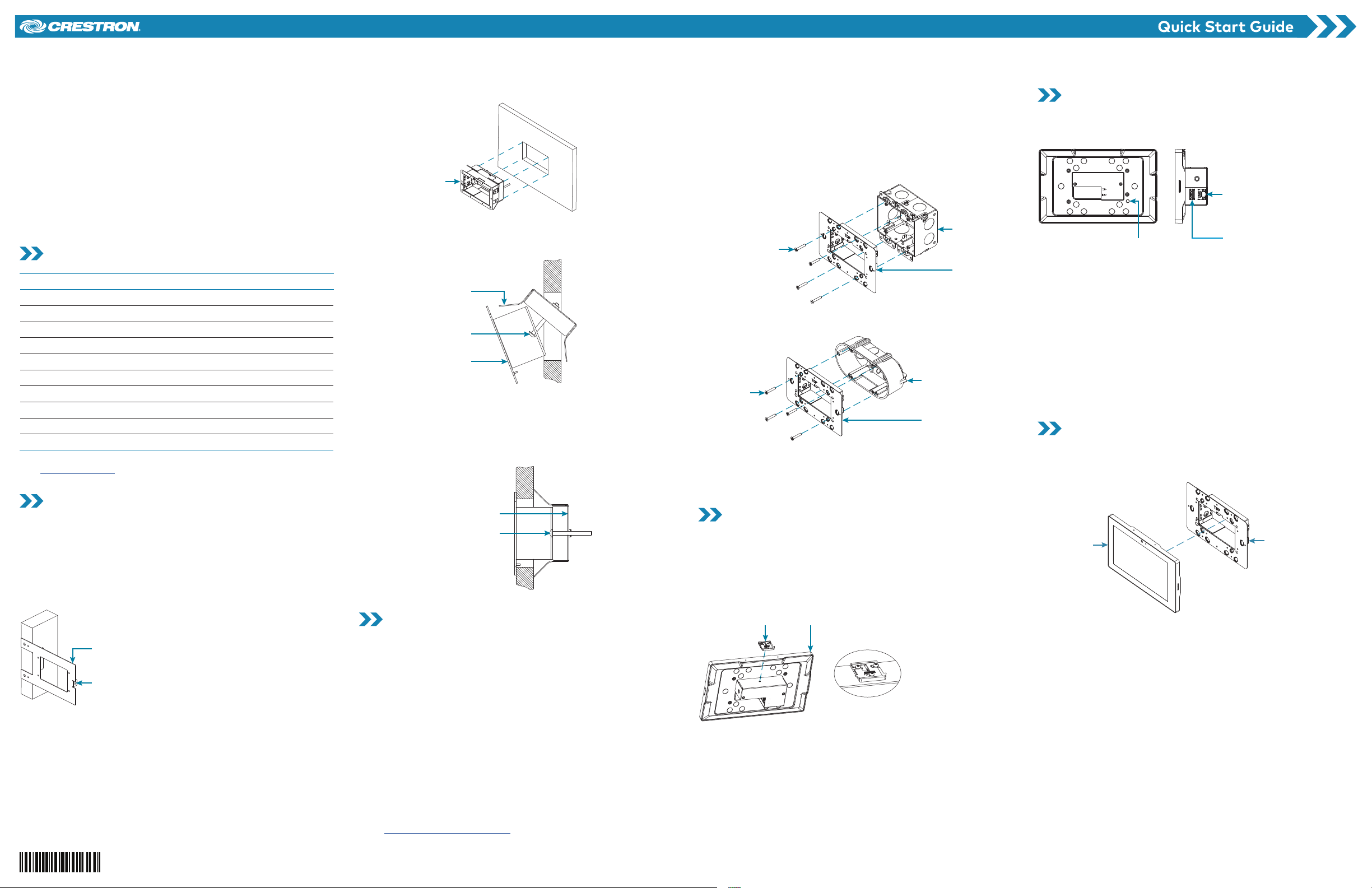
Connect the Touch Screen
Route all necessary cables through the rear of the electrical box, and
then make connections to the touch screen as shown in the illustration
below.
LAN PoE:
10BASE-T / 100BASE-TX
Ethernet to LAN
USB:
Reset button
To LED accessories
Observe the following when connecting the touch screen:
• Use Crestron power supplies for Crestron equipment.
• Power and data connection is provided to the touch screen by
a single Ethernet cable. A Crestron PoE (Power over Ethernet)
power supply, such as the PWE-4803RU, or a PoE-capable
network switch is recommended (both not included).
• The USB port is used to connect compatible Crestron LED
accessories to the touch screen.
NOTE: The TSW-760 may use either PoE or PoE+ to supply power
to compatible LED accessories over USB; the TSW-1060 must
use only PoE+ to supply power to LED accessories over USB.
• Apply power after all connections have been made.
Install the Touch Screen
Once all connections have been made, push the touch screen gently
into the mounting bracket so that the touch screen rear housing is
secured within the center opening in the mounting bracket.
Touch screen
If the touch screen is not level after installation, pull it out of the
mounting bracket and loosen the screws holding the bracket into place.
This procedure allows the mounting bracket to be rotated slightly.
Once the mounting bracket has been repositioned, retighten the
screws, reinstall the touch screen into the bracket, and ensure that the
touch screen is now level.
Mounting
bracket
Page 2
Remove the Touch Screen
Mounting
here.
To remove the touch screen after installation, carefully pull the touch
screen away from the wall until it disengages from the mounting
bracket.
To remove the touch screen if the security latch has been installed:
1. Pull the touch screen away from the wall until the security latch
makes contact with the mounting bracket.
2. Insert a flat-head screwdriver into the slot on the security latch
and rotate the latch into the open position, which retracts the
security latch arms.
3. With the arms retracted, pull on the touch screen to disengage it
from the mounting bracket.
bracket
(top view)
Touch
screen
Insert the
screwdriver
Security
latch
NOTE: There is a small amount of “play” in the bracket mounting, which
allows room to insert the screwdriver.
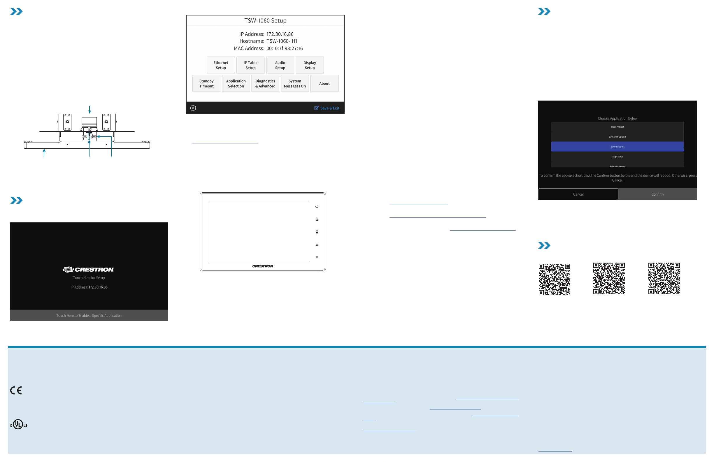
Configure the Device
When power is applied for the first time, the following screen is
displayed. The touch screen may take up to two minutes to boot.
Touch the screen to display the main Setup screen (TSW-1060 shown).
Device settings for the touch screen may be configured using the
built-in setup screens or the web configuration interface. For more
information on configuring the touch screen, refer to the
TSW-560/TSW-760/TSW-1060 Supplemental Guide (Doc. 7927)
at www.crestron.com/manuals.
Access the Device Setup Screens
To access the built-in setup screens for configuring device settings, do
either of the following:
• Place five fingers on the display and hold for 15 seconds.
• Press the hard keys labeled in the illustration below as 1, 2, 3, and
4 twice, in this sequence, within five seconds.
1
2
3
4
Use the setup screens to configure various settings for the touch
screen, including Ethernet setup, IP table setup, audio setup, display
setup, standby timeout, and diagnostics.
Access the Web Configuration Interface
The touch screen also provides a web configuration interface that is
used to view and configure various touch screen settings and to select
an application. The interface can be accessed using the touch screen IP
address or the Crestron XiO Cloud™ service.
Touch Screen IP Address
To access the web configuration interface using the touch screen IP
address:
1. Ensure that the touch screen is connected to the network.
2. Use the Device Discovery tool in Crestron Toolbox™ software to
discover the touch screen and its IP address on the network.
3. Enter the touch screen IP address into a web browser.
Crestron XiO Cloud Service
The Crestron XiO Cloud service allows supported Crestron devices
across an enterprise to be managed and configured from one central
and secure location in the cloud. Supported devices are configured to
connect to the ser vice. Use of the service requires a registered
Crestron XiO Cloud account.
NOTE: The device may be disconnected from the service by navigating
to the Cloud Services tab in Crestron Toolbox software (Functions >
Device Info > Cloud Services). For details, refer to the Crestron Toolbox
help file.
To access the web configuration interface using the Crestron XiO Cloud
service:
1. Record the MAC address and serial number that are labeled on
the shipping box or rear panel of the device. The MAC address and
serial number are required to add the device to the service.
2. Do either of the following:
• For existing accounts, access the Crestron XiO Cloud service
at https://portal.crestron.io.
• For new accounts, register for a Crestron XiO Cloud account
at www.crestron.com/xio-cloud-registration.
3. Claim the device to the service as described in the Crestron XiO
Cloud User Guide (Doc. 8214) at www.crestron.com/manuals.
4. Select the device from the cloud interface to view its settings.
Set the Time Zone
The time zone must be set on the touch screen if it will not be paired
with a control system IP table.
To set the time zone:
1. Access the web configuration interface using either the touch
screen IP address or the Crestron XiO Cloud service.
2. Navigate to Settings > Configure Date/Time.
3. Select the time zone where the touch screen will be used from the
Time Zone drop-down menu.
4. Click Save Changes on the top right of the screen.
Select an Application
The touch screen ships with a selection of built-in applications. An
application may be selected from the splash screen that displays after
power is applied to the touch screen for the first time.
NOTE: Applications can be selected and configured from the device
setup screens or from the web configuration interface at any time. For
more information on configuring applications, refer to the
TSW-560/TSW-760/TSW-1060 Supplemental Guide (Doc. 7927).
To select a touch screen application:
1. Tap the Touch Here to Enable a Specific Application bar on the
bottom of the splash screen. Refer to the first image in the
“Configure the Device” section.
2. Select the desired touch screen application from the Choose
Application Below menu that is displayed.
3. Click Confirm. The touch screen reboots to display the user
interface for the selected application.
NOTE: If a custom user project will be used in place of an application,
tap User Project. Custom projects can be uploaded using the web
configuration interface or Crestron Toolbox software.
Additional Information
Scan or click the QR code for detailed product information.
TSW-560-B-S TS W-760-B -S TSW-1060-B-S
Compliance and Legal
Original Instructions: The U. S. Engl ish version of this document is t he original in stru ctio ns. All
other languages are a translation of the original instructions.
Regulatory Models: TSW-560 TSW-760 TSW-1060
As of the date of ma nufac ture, t he prod uct ha s been te sted and found to compl y with
specifications for CE marking.
This pro duct i s Listed to applicabl e UL® Standards and requi rements tested by Und erw riters
Laboratories Inc.
Ce produ it est h omolo gué selon les n ormes et les exigence s UL applicabl es par Un derwriters
Laboratories Inc.
Federal Communications Commission (FCC) Compliance Statement
This dev ice complies with par t 15 of the FCC Rules. Op eration is subj ect to t he foll owing
condit ions: ( 1) This d evice m ay not cause harmful interference and (2) this device m ust accept
any inter feren ce received, includi ng inter ference that ma y cause undesi red ope ratio n.
CAUTION: Changes or modifications not expressly approved by the manufacturer responsible
for compliance could voi d the user’s aut horit y to operate the equipme nt.
NOTE: This e quipm ent has b een tested an d found to comply w ith the limit s for a Class B
digital device, pursuant to par t 15 of the FCC Rules. Th ese limits are d esign ed to provide
reasonable protection against harmful interference in a residential installation. This
equipm ent gen erates, uses and can radiate radio freq uenc y energ y and, if n ot installed
and used in accord ance wi th the instru ctio ns, ma y cause harmful i nterference to radio
communicatio ns. However, there i s no guarantee th at interfere nce will not occu r in a
part icular installatio n. If this equipment does caus e harmf ul inter ference to radio or
televi sion re ceptio n, which can be de termined by tur ning th e equip ment of f and on , the user is
encouraged to try to correct t he interference by one or more of the foll owing m easur es:
• Reori ent or relocate t he receiving a ntenna .
• Increase the separation between the equipment and receiver.
• Conne ct the equipment into an outl et on a circ uit dif feren t from that to whic h the
receiver is connected.
• Consu lt the de aler or an experienced radio/ TV technici an for he lp.
Industry Canada (IC) Compliance Statement
CAN ICE S-3 (B)/N MB-3 (B)
Crestron prod uct development softwa re is lice nsed to Crestron deal ers and Crestron Ser vice
Providers (CSPs) under a limi ted non -exclusive, non-transferable Sof twar e Developmen t
Tools License Agre ement. Cres tron product operating system s oft ware is licensed to Crest ron
dealers, CSPs, and e nd-users under a separate End -User Licens e Agreement . Both of these
Agreem ents can be found on the Crestron websi te at www.crestron.com/legal/software_
license_agreement.
The product wa rrant y can be fo und at www.crestron.com/warranty.
The spe cific patent s that cover Crestron p roduc ts are l isted at www.crestron.com/legal/
patents.
Certa in Cres tron products contain open source s oft ware. For speci fic informat ion, please v isit
www.crestron.com/opensource.
Crestron, the Crestron logo, Crest ron Toolbox, Cres tron XiO Cloud , Rava, and Smar t Grap hics
are eith er trad emark s or registere d trademark s of Crestron Ele ctro nics , Inc. , in the Un ited
States an d/or other countries. UL and the U L logo are either trademark s or registere d
tradem arks of Under writers Lab orato ries, Inc. in t he Unit ed States and/or oth er count ries .
Other trademarks , regis tered t radem arks , and tra de name s may be u sed in this document to
refer to ei ther the entities claiming t he marks and na mes or their pro duct s. Cre stron discla ims
any propr ietar y interest in the mark s and nam es of oth ers. Crestron is not re sponsible fo r
errors in typography or photography.
©2019 Crestron Electronics, Inc.
Crestron Electronics, Inc.
15 Volvo Dr ive, Rockleig h, NJ 07647
Tel: 888.CRESTRON
Fax: 201.767.7576
www.crestron.com
Quick Start - Doc. 79 26F
Specifications subject to
change without notice
(2053121)
06 /07/1 9
 Loading...