

Page 1
Page 2

Page 3

Crestron TPS-VIDL Video Card for TPS/Lectern Panel
Contents
Video Card for TPS/Lectern Panel: TPS-VIDL 1
Description 1
Functional Description 1
Physical Description 1
Leading Specifications 2
Connector Specifications 3
Installation and Hookup 3
Problem Solving 8
Troubleshooting 8
Further Inquiries 8
Return and Warranty Policies 9
Merchandise Returns / Repair Service 9
CRESTRON Limited Warranty 9
Operations & Installation Guide - DOC. 5830 Contents • i
Page 4

Page 5
Crestron TPS-VIDL Video Card for TPS/Lectern Panel
Video Card for TPS/Lectern Panel: TPS-VIDL
Description
Functional Description
The TPS-VIDL video card is an optional feature designed for Crestron’s wall/ lectern
mounted TPS-5000L and TPS-6000L touchpanels and the TPS-TPI touchpanel interface. The
card is a video digitizer that allows television (TV) National Television System Committee
(NTSC) or Phase Alternating Line (PAL) video to be displayed on the touchpanel. Composite
or S-Video formats are supported and the TV video can be displayed in a window or full
screen.
NOTE: A video window object must reside on a page within the uploaded VT Pro-e
touchpanel project and the TPS-VIDL must be installed into the proper expansion slot of the
TPS-5000L, TPS-6000L, or TPS-TPI in order for the TV video to be displayed. For details
regarding video window objects, refer to the VT Pro-e help file.
Physical Description
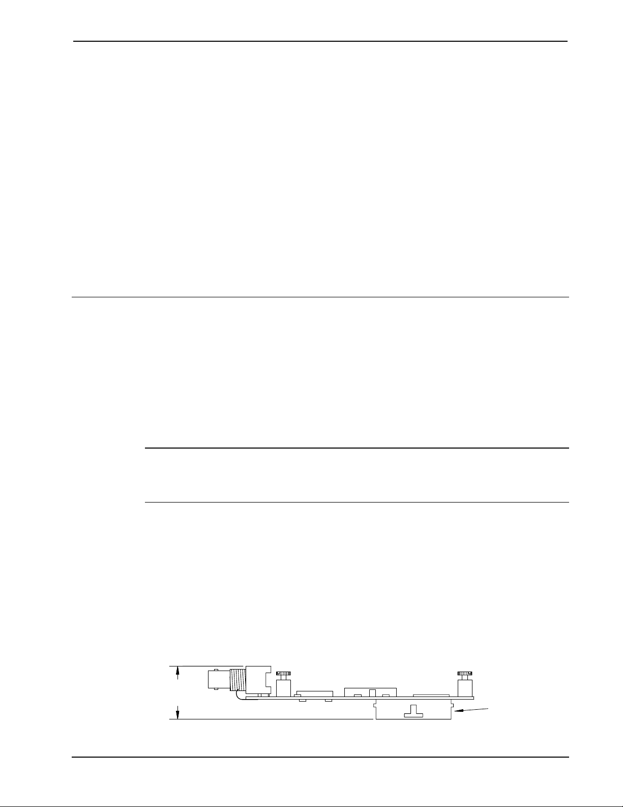
The TPS-VIDL card, shown below and on the next page, is a printed circuit board (PCB)
designed to be installed into a specific expansion slot in the touchpanel (or interface). The
card contains a 60-pin connector that attaches directly to the motherboard. TV video access is
through two BNC connectors and a 6-pin port that are permanently attached to the TPS-VIDL
card. The connectors and port (individually labeled in the NTSC/PAL INPUT section of the
touchpanel) are accessible through the connector panel at the rear of the case. The card is
secured to the motherboard with four attached knurled mounting screws.
TPS-VIDL Side View
1.16 in
(2.95 cm)
Operations & Installation Guide - DOC. 5830 Video Card for TPS/Lectern Panel: TPS-VIDL • 1
TOUCHPANEL
INTERFACE
CONNECTOR
Page 6

Video Card for TPS/Lectern Panel Crestron TPS-VIDL
TPS-VIDL Top View
2.63 in
(6.67 cm)
5.00 in
(12.70 cm)
Leading Specifications
The table below provides a summary of leading specifications for the TPS-VIDL.
Dimensions and weight are rounded to the nearest hundredth unit.
Leading Specifications of the TPS-VIDL
SPECIFICATION DETAILS
Power Requirements 24VDC Cresnet power, load factor of
8 Watts.
Video Types NTSC or PAL
Video Formats Composite or S-Video
Video Format Detection Within 4-seconds.
SIMPL™ Windows®
Version 1.40.07 or later
addition of smwlib89.exe and
smwlib89.txt.
CNMXSX-AV/Pro Update File
CNRACKX/-DP Update File
Version 51011X or later.
Version 51011W or later.
Dimensions & Weight Height: 1.16 in (2.95 cm)
Width: 2.63 in (6.67 cm)
Depth: 5.00 in (12.70 cm)
Weight: 3.20 oz (0.09 kg)
1 The latest software version can be obtained from the Downloads page (SIMPLWIN Library)
of Crestron’s website (www.crestron.com). New users are required to register in order to
obtain access to the FTP site.
2 Filenames for update files have a UPZ extension and can be obtained from the Downloads
page (OPSYS Library) of Crestron’s website.
1
with the
2
2
As of the date of manufacture, this unit has been tested and found to comply with
specifications for CE marking.
2 • Video Card for TPS/Lectern Panel: TPS-VIDL Operations & Installation Guide - DOC. 5830
Page 7

Crestron TPS-VIDL Video Card for TPS/Lectern Panel
NOTE: This device complies with part 15 of the FCC rules. Operation is subject to the
following two conditions: (1) this device may not cause harmful interference, and (2) this
device must accept any interference received, including interference that may cause undesired
operation.
Connector Specifications
Connector Specifications of the TPS-VIDL
PORT TYPE SIGNAL(S)
Touchpanel
Interface
C + 6-pin connector, 3.5mm S-Video chrominance input #1
C - 6-pin connector, 3.5mm S-Video chrominance return
C S 6-pin connector, 3.5mm S-Video chrominance shield
Y + 6-pin connector, 3.5mm S-Video luminance input or composite
Y - 6-pin connector, 3.5mm S-Video luminance return
Y S 6-pin connector, 3.5mm S-Video luminance shield
C BNC S-Video chrominance (color
COMP / Y BNC Composite video or S-Video
60-pin connector Various
input #1
information) input #2
luminance (brightness) input #2
Installation and Hookup
The TPS-VIDL is designed to be installed into a specific expansion slot in the TPS-5000L
and TPS-6000L touchpanel and the TPS-TPI touchpanel interface. The tools required for
installation are a grounding strap (or grounded workstation), #1 Phillips screwdriver, #1
Phillips 1/4-inch hex bit and an inch-pound torque driver.
CAUTION: The TPS-VIDL and the touchpanel contain electrostatic sensitive devices
(ESDs); observe precautions for handling ESDs to avoid damaging the card and/or the
touchpanel.
NOTE: The diagrams in this procedure show a TPS-6000L touchpanel but the steps for the
TPS-5000L and TPS-TPI are identical. This procedure pertains to a touchpanel or interface
that is NOT installed into a wall or lectern. If already installed, refer to the latest revision of
the TPS-5000L, TPS-6000L, or TPS-TPI Operations & Installation Guide (Doc. 5825, 5783,
or 5855, respectively) or, if applicable, BB-5000 or BB-6000 Installation Guide (Doc. 5826
or 5827). Disconnect power and perform the installation procedure in reverse to remove the
touchpanel or interface. The latest software version of the Operations & Installation Guide
can be obtained from the Downloads page (MANUAL Library) of Crestron’s website
(www.crestron.com). New users are required to register in order to obtain access to the FTP
site.
1. To prevent scratching of the screen (TPS-TPI excluded), place the touchpanel
face-down onto a padded surface.
Operations & Installation Guide - DOC. 5830 Video Card for TPS/Lectern Panel: TPS-VIDL • 3
Page 8
Video Card for TPS/Lectern Panel Crestron TPS-VIDL
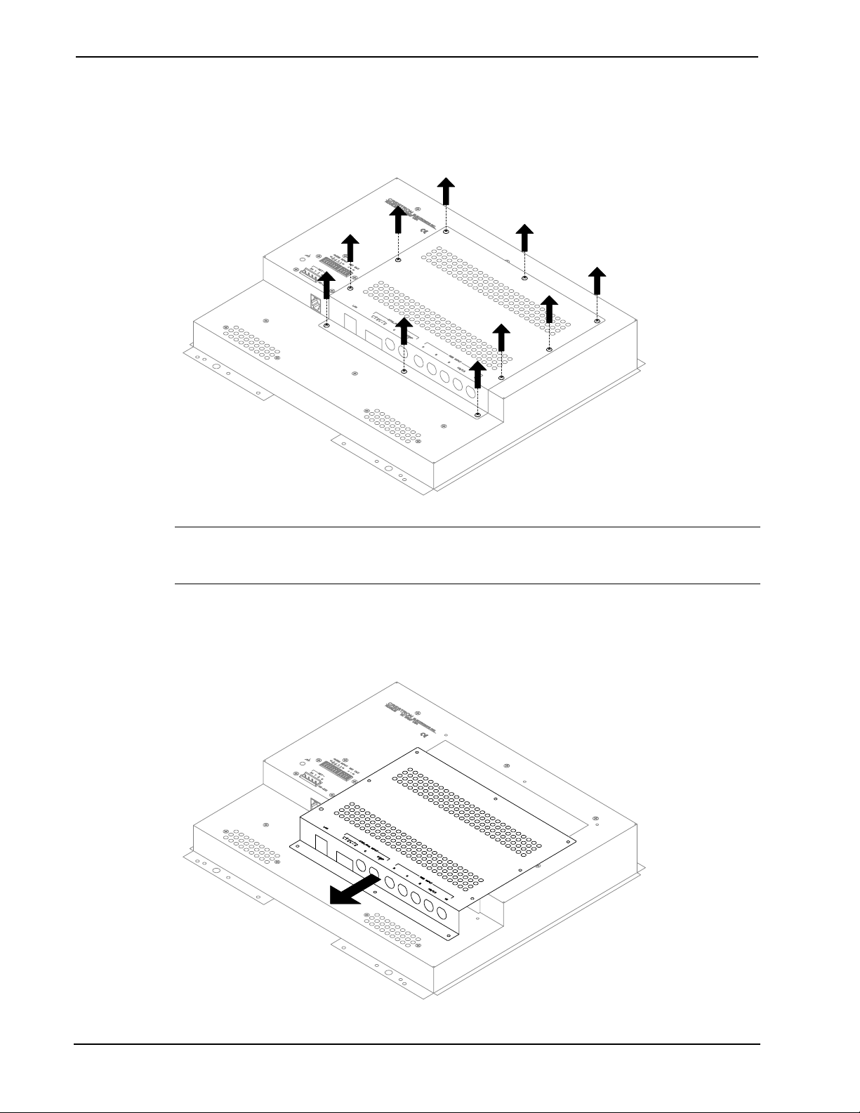
2. Refer to the diagram below. Using a #1 Phillips screwdriver, loosen and remove
the 10 screws that secure the touchpanel rear cover.
Remove Touchpanel Rear Cover Screws
CAUTION: The connectors of any optional card that is already installed may have to be
aligned slightly to allow the rear cover to be removed. Align the connectors carefully to
prevent damage to the card, cover, or touchpanel.
3. Remove the touchpanel rear cover by sliding it towards the bottom of the
touchpanel as shown below.
Remove Touchpanel Rear Cover
4 • Video Card for TPS/Lectern Panel: TPS-VIDL Operations & Installation Guide - DOC. 5830
Page 9

Crestron TPS-VIDL Video Card for TPS/Lectern Panel
4. Refer to the diagram below. Using a #1 Phillips screwdriver, loosen and remove
the two screws that secure the PCB blank plate and remove the plate.
Remove PCB Blank Plate
5. As shown below, align the pins on the touchpanel interface connector of the
TPS-VIDL with the touchpanel motherboard connector.
Install TPS-VIDL
6. DO NOT force pins into connector. Press TPS-VIDL until pins are fully seated.
Make sure that the mounted screws align with mounting posts of the
motherboard.
7. Tighten the card mounting screws to finger-tight.
Operations & Installation Guide - DOC. 5830 Video Card for TPS/Lectern Panel: TPS-VIDL • 5
Page 10

Video Card for TPS/Lectern Panel Crestron TPS-VIDL
CAUTION: The TPS-VIDL connectors may have to be aligned slightly to fit through the
openings in the rear cover. Align the connectors of this card (or any other optional card that is
installed) carefully to prevent damage to the card, cover, or touchpanel.
8. As shown below, install the touchpanel rear cover by sliding it over the
TPS-VIDL connectors.
Install Touchpanel Rear Cover
9. Refer to the diagram below. Using a #1 Phillips 1/4-inch hex bit and an inchpound torque driver, install 10 screws and tighten to 4-inch pounds (0.45
Newton-meters) to secure cover.
Install Touchpanel Rear Cover Screws
6 • Video Card for TPS/Lectern Panel: TPS-VIDL Operations & Installation Guide - DOC. 5830
Page 11

Crestron TPS-VIDL Video Card for TPS/Lectern Panel
NOTE: Depending upon the individual installation, video connectors #1 or #2 may be used.
The input signals are identical, only the connector type is different.
10. Refer to the diagram below and make the appropriate S-video or composite video
connection(s) as shown.
Attach Appropriate Video Cables
VIDEO
CONNECTORS #1
{
CY
NTSC/PAL INPUT
S
VIDEO
{
CONNECTORS #2
COMP
CS++- - Y
FROM
S-VIDEO
CHROMINANCE
OUTPUT
NOTE: Refer to the latest revision of the TPS-5000L, TPS-6000L, or TPS-TPI Operations
& Installation Guide (Doc. 5825, 5783, or 5855, respectively) or, if applicable, BB-5000 or
BB-6000 Installation Guide (Doc. 5826 or 5827, respectively) for the proper installation
procedure of the touchpanel. The latest software version of the Operations & Installation
Guides can be obtained from the Downloads page (MANUAL Library) of Crestron’s website
(www.crestron.com).
NOTE: Refer to the latest revision of the TPS-5000L, TPS-6000L, or TPS-TPI Operations
& Installation Guide (Doc. 5825, 5783, or 5855, respectively) to configure the touchpanel for
video input.
FROM S-VIDEO
LUMINANCE
OR COMPOSITE
VIDEO OUTPUT
FROM
S-VIDEO
CHROMINANCE
OUTPUT
FROM S-VIDEO
LUMINANCE
OR COMPOSITE
VIDEO OUTPUT
Operations & Installation Guide - DOC. 5830 Video Card for TPS/Lectern Panel: TPS-VIDL • 7
Page 12

Video Card for TPS/Lectern Panel Crestron TPS-VIDL
Problem Solving
Troubleshooting
The table below provides corrective action for possible trouble situations. If further assistance
is required, please contact a Crestron technical support representative.
TPS-VIDL Troubleshooting
TROUBLE
Video window of
touchpanel has
no display.
POSSIBLE
CAUSE(S)
Improper video
connection(s).
Incorrect video format
selected.
Incorrect
firmware/software.
Incorrect VT Pro-e
project file loaded.
TPS-VIDL improperly
installed.
Damaged connector
pins.
Further Inquiries
CORRECTIVE ACTION
Verify proper connections at
NTSC/PAL INPUT ports.
Select proper video format or autodetect in touchpanel configuration
setup menu.
Upgrade firmware/software
versions as per those listed in the
"Leading Specifications" section of
this guide.
Make sure that video window
object resides in project, recompile, and reload.
Follow installation procedures in
this guide.
Inspect connector pins. If bent,
carefully re-straighten. If broken,
contact Crestron technical support.
If after reviewing this Operations & Installations Guide, you cannot locate specific
information or have questions, please take advantage of Crestron's award winning technical
support team by calling:
• In the US and Canada, call Crestron’s corporate headquarters at
1-888-CRESTRON [1-888-273-7876] or 1-201-767-3400.
• In Europe, call Crestron International at +32-15-50-99-50.
• In Asia, call Crestron Asia at +852-2341-2016.
• In Latin America, call Crestron Latin America at +5255-5093-2160.
• In Australia, call Crestron Pacific at +613-9480-2999.
For local support from exclusive Crestron factory-trained personnel in New Zealand call
Amber Technologies at +649-410-8382.
8 • Video Card for TPS/Lectern Panel: TPS-VIDL Operations & Installation Guide - DOC. 5830
Page 13

Crestron TPS-VIDL Video Card for TPS/Lectern Panel
Return and Warranty Policies
Merchandise Returns / Repair Service
1. No merchandise may be returned for credit, exchange, or service without prior authorization
from CRESTRON. To obtain warranty service for CRESTRON products, contact the factory
and request an RMA (Return Merchandise Authorization) number. Enclose a note specifying
the nature of the problem, name and phone number of contact person, RMA number, and
return address.
2. Products may be returned for credit, exchange, or service with a CRESTRON Return
Merchandise Authorization (RMA) number. Authorized returns must be shipped freight
prepaid to CRESTRON, Cresskill, N.J., or its authorized subsidiaries, with RMA number
clearly marked on the outside of all cartons. Shipments arriving freight collect or without an
RMA number shall be subject to refusal. CRESTRON reserves the right in its sole and
absolute discretion to charge a 15% restocking fee, plus shipping costs, on any products
returned with an RMA.
3. Return freight charges following repair of items under warranty shall be paid by CRESTRON,
shipping by standard ground carrier. In the event repairs are found to be non-warranty, return
freight costs shall be paid by the purchaser.
CRESTRON Limited Warranty
CRESTRON ELECTRONICS, Inc. warrants its products to be free from manufacturing defects in
materials and workmanship under normal use for a period of three (3) years from the date of
purchase from CRESTRON, with the following exceptions: disk drives and any other moving or
rotating mechanical parts, pan/tilt heads and power supplies are covered for a period of one (1)
year; touchscreen display and overlay components are covered for 90 days; batteries and
incandescent lamps are not covered.
This warranty extends to products purchased directly from CRESTRON or an authorized
CRESTRON dealer. Purchasers should inquire of the dealer regarding the nature and extent of the
dealer's warranty, if any.
CRESTRON shall not be liable to honor the terms of this warranty if the product has been used in
any application other than that for which it was intended, or if it has been subjected to misuse,
accidental damage, modification, or improper installation procedures. Furthermore, this warranty
does not cover any product that has had the serial number altered, defaced, or removed.
This warranty shall be the sole and exclusive remedy to the original purchaser. In no event shall
CRESTRON be liable for incidental or consequential damages of any kind (property or economic
damages inclusive) arising from the sale or use of this equipment. CRESTRON is not liable for
any claim made by a third party or made by the purchaser for a third party.
CRESTRON shall, at its option, repair or replace any product found defective, without charge for
parts or labor. Repaired or replaced equipment and parts supplied under this warranty shall be
covered only by the unexpired portion of the warranty.
Except as expressly set forth in this warranty, CRESTRON makes no other warranties, expressed
or implied, nor authorizes any other party to offer any other party to offer any warranty, including
any implied warranties of merchantability or fitness for a particular purpose. Any implied
warranties that may be imposed by law are limited to the terms of this limited warranty. This
warranty statement supercedes all previous warranties.
Trademark Information
All brand names, product names, and trademarks are the sole property of their respective owners. Windows is a registered
trademark of Microsoft Corporation. Windows95/98/Me/XP and WindowsNT/2000 are trademarks of Microsoft
Corporation.
Operations & Installation Guide - DOC. 5830 Video Card for TPS/Lectern Panel: TPS-VIDL • 9
Page 14

Video Card for TPS/Lectern Panel Crestron TPS-VIDL
This page intentionally left blank.
10 • Video Card for TPS/Lectern Panel: TPS-VIDL Operations & Installation Guide - DOC. 5830
Page 15

Crestron TPS-VIDL Video Card for TPS/Lectern Panel
This page intentionally left blank.
Operations & Installation Guide - DOC. 5830 Video Card for TPS/Lectern Panel: TPS-VIDL • 11
Page 16

 Loading...