

Page 1

Crestron SIMPL™ Windows®
Software
Installation & Operations Guide
Page 2

This document was prepared and written by the Technical Documentation department at:
Crestron Electronics, Inc.
15 Volvo Drive
Rockleigh, NJ 07647
1-888-CRESTRON
All brand names, product names and trademarks are the property of their respective owners.
©2002 Crestron Electronics, Inc.
Page 3

Crestron SIMPL™ Windows Software
Contents
Introduction 1
The Intent of this SIMPL™ Windowsâ Manual ...................................................1
SIMPL Windows New Features ..........................................................................1
SIMPL™ Windowsâ Review and Programming Preparation.............................. 3
SIMPL™ Windowsâ ...............................................................................3
System Design & Programming Process............................................... 3
Crestron’s Programming Design Kit ...................................................... 4
VisionTools™ Pro-e ...............................................................................4
Programming Process ...........................................................................4
Contact Crestron Electronics, Inc. ......................................................................6
Trademark Information........................................................................................ 6
Installing SIMPL™ Windows® 7
System Requirements......................................................................................... 7
Crestron Database Requirements ......................................................................7
Installing from the Crestron Web Site .................................................................7
Installing from the Crestron ControlCD............................................................... 8
Uninstall SIMPL™ Windows®.............................................................................8
DOS Workshop 11
Migration to SIMPL Windows............................................................................ 11
Changes from Workshop .................................................................................. 11
Symbol CrossReference ...................................................................... 11
SpeedKey.............................................................................................12
KeyCombo Shortcut Table................................................................... 12
Feature Comparison .........................................................................................14
Importing Workshop Programs .........................................................................15
SIMPL™ Windows®– Getting Started 17
SIMPL Windows Applications ...........................................................................17
Opening SIMPL Windows ................................................................................. 18
Set Directory Paths ...........................................................................................18
Create A New Program.....................................................................................19
Program Header ..................................................................................19
Configuration Manager 21
Accessing Configuration Manager.................................................................... 21
Configuration Manager Navigation ...................................................................22
Installation & Operations Guide – DOC. 5728C Crestron SIMPL Windows • i
Page 4

Software Crestron SIMPL™ Windows
Device Library ......................................................................................22
Network System View ..........................................................................24
Detail System View ..............................................................................24
System Device Tree............................................................................. 24
Configuration Manager Button Bar ...................................................................25
Configuring the System..................................................................................... 26
Selecting Hardware..............................................................................26
Replacing Devices ...............................................................................28
Configure System Control Devices...................................................... 28
Configure User Devices .......................................................................34
Deleting Devices ..................................................................................39
Automatically Configure Devices .........................................................39
Importing VisionTools™ for Windowsâ and VisionTools™ Pro-e Projects.......40
Default Logic from Crestron Database .............................................................42
Program Manager 43
Accessing Program Manager............................................................................43
Screen Navigation............................................................................................. 44
Symbol Library .....................................................................................44
Program View.......................................................................................45
Detail View ...........................................................................................47
Bookmark ............................................................................................. 47
World View........................................................................................... 48
Signal Tray........................................................................................... 49
Program Manager Button Bar........................................................................... 50
Programming in SIMPL Windows .....................................................................51
Symbols & Signals ............................................................................................52
Symbol Properties................................................................................ 52
Symbol Categories............................................................................... 54
Symbol Title Bar................................................................................... 54
Programming a System ....................................................................................55
Define Signals from User Interface...................................................... 55
Using Logic Symbols ...........................................................................57
Naming Signals.................................................................................... 59
Subsystems..........................................................................................60
Programming with User Interfaces....................................................................61
Feedback .............................................................................................61
Indirect Text .........................................................................................63
Imported UI Projects ............................................................................63
Using Macros ....................................................................................................64
Crestron Macros ..................................................................................65
User Macros......................................................................................... 66
Device Programming Information 71
Serial Driver Programming Information ............................................................71
[TX$].....................................................................................................71
[RX$] ....................................................................................................71
[BREAK] ............................................................................................... 71
[RTS] .................................................................................................... 72
[CTS] .................................................................................................... 72
Other Lines...........................................................................................72
[enable] ................................................................................................72
ii • Crestron SIMPL Windows Installation & Operations Guide – DOC. 5728C
Page 5

Crestron SIMPL™ Windows Software
Programming Features 73
Signal Colors..................................................................................................... 73
Signal Operations .............................................................................................74
Navigating Symbol Inputs and Outputs ...............................................74
Create New Signals .............................................................................74
Selecting Signals .................................................................................75
Edit Signal Name .................................................................................75
Rename Signal Globally ......................................................................76
Disconnect a Signal .............................................................................76
Replacing a Signal ............................................................................... 77
Connect Signals................................................................................... 77
Naming a Parameter............................................................................78
Automatically Increase Inputs, Outputs, or Parameters ......................78
Decrease Inputs, Outputs, or Input/Output Pairs.................................80
Automatically Assign Unique Signal Name(s) .....................................80
Signal Routing...................................................................................... 81
Auto-Increment the First Number.........................................................82
Auto-Increment the Last Number......................................................... 83
Auto-Increment the Last Number in a Signal Name ............................83
Copying Signal Names ........................................................................84
Append a Signal Suffix.........................................................................85
SIMPL Windows ExampleBase ........................................................................86
How to Re-Synch Your Programs..................................................................... 86
Compile Programs 87
Compiler Settings.............................................................................................. 87
Compiling the Program .....................................................................................88
Consider Commented Out Symbols and Devices ............................................90
Sharing Programs 91
Copy Program................................................................................................... 91
Import Archived Program ..................................................................................92
Test Manager 93
Test Manager Overview....................................................................................93
Accessing Test Manager ..................................................................................93
Screen Navigation............................................................................................. 94
Trace Window ......................................................................................94
Status Window .....................................................................................94
Incoming Data...................................................................................... 95
Testing a Program ............................................................................................95
SIMPL Procedures Before Testing ......................................................95
Begin Testing with Test Manager ........................................................98
ViewPort 101
Viewport Overview ......................................................................................... 101
Communication Settings................................................................................ 101
Hardware Configuration .................................................................................102
Viewport: File Menu ....................................................................................... 103
Viewport: Edit Menu....................................................................................... 103
Viewport: Setup Menu.................................................................................... 103
Installation & Operations Guide – DOC. 5728C Crestron SIMPL Windows • iii
Page 6

Software Crestron SIMPL™ Windows
Viewport: Diagnostics Menu .......................................................................... 107
Viewport: Functions Menu ............................................................................. 110
CNX/CN Series .............................................................................................. 110
General .......................................................................................................... 113
Viewport: File Transfer Menu......................................................................... 117
Viewport: Remote Menu ................................................................................ 124
Viewport Shortcut Keys.................................................................................. 127
Network Analyzer 129
Overview .........................................................................................................129
Using Network Analyzer..................................................................................129
Starting Network Analyzer .................................................................130
Communication Settings.................................................................... 130
Opening Existing Files .......................................................................131
Acquiring New Data ...........................................................................132
Network Analyzer Analysis .............................................................................133
"Delta Y on transmit is too small"....................................................... 133
"Delta Z on transmit is too small"....................................................... 133
"Y and Z lines are not symmetrical on transmit"................................ 134
"Delta Y and Delta Z are not within 25% on transmit" .......................134
"Y voltage is too high on transmit" .....................................................134
"Z voltage is too high on transmit" .....................................................135
"Y voltage is too low on transmit".......................................................135
"Z voltage is too low on transmit".......................................................135
"Y and Z voltages do not overlap on transmit"...................................135
"Delta Y on receive is too small"........................................................ 136
"Delta Z on receive is too small" ........................................................136
"Y and Z lines are not symmetrical on receive" .................................136
"Delta Y and Delta Z are not within 25% on receive".........................136
"Y voltalge is too high on receive"......................................................137
"Z voltage is too high on receive".......................................................137
"Y voltage is too low on receive"........................................................137
"Z voltage is too low on receive" ........................................................ 138
"Minimum Y voltage is too high on receive".......................................138
"Minimum Z voltage is too high on receive".......................................138
"Y and Z voltages do not overlap on receive"....................................138
Crestron e-Control™ 139
Ethernet Communications...............................................................................139
Network Requirements/Preparation................................................................ 139
Hardware Preparation – CNMSX-AV and Pro ................................................ 140
Hardware Preparation – CEN-IO ....................................................................141
Control System Diagnostics via Ethernet .......................................................141
Programming the System to Communicate with Ethernet Devices ................ 141
Adding Ethernet Devices to a SIMPL Windows Program..................141
Changing IP Addresses without Changing the Program ...................143
System-to-System Communication ...................................................144
Crestron e-control SDK......................................................................146
Ethernet Connection Information ....................................................................146
Recommended Connection ...............................................................146
Isolated Network Connection............................................................. 146
iv • Crestron SIMPL Windows Installation & Operations Guide – DOC. 5728C
Page 7

Crestron SIMPL™ Windows Software
Front Panel Editor 147
Front Panel Overview .....................................................................................147
Accessing Front Panel Editor..........................................................................147
Screen Navigation........................................................................................... 147
Front Panel Editor Buttons..............................................................................148
Page Buttons .....................................................................................148
Front Panel Editor Programming ....................................................................150
Adding Pages..................................................................................... 151
Adding Objects to Pages ...................................................................151
Active/Inactive Text and Join Numbers .............................................155
SIMPL™ Windows® Menu Definitions 159
Configuration & Program Manager .................................................................159
Program Manager Right Mouse Click Menus.................................... 163
Front Panel Editor ...........................................................................................164
Test Manager.................................................................................................. 165
ViewPort..........................................................................................................167
Network Analyzer Menu Definitions................................................................171
SIMPL+ Menus ...............................................................................................172
SIMPL+ Right Mouse Click Menus ....................................................173
SIMPL+™ 175
SIMPL+ Overview ...........................................................................................175
Accessing SIMPL+..........................................................................................176
SIMPL+ Programming Text Colors .................................................................177
Saving and Compiling SIMPL+ Files ..............................................................177
SIMPL+ New File Template ............................................................................178
Symbol Card File 179
SIMPL Windows Errors 181
SIMPL Windows Errors Defined .....................................................................181
Device Library Error ...........................................................................181
Symbol Library Error ..........................................................................181
Error Importing SmarTouch System ..................................................181
Program Data Integrity Checks.......................................................... 181
Program Load/Save Error .................................................................. 182
Swapping Devices Error ....................................................................182
Error in Moving a Device....................................................................182
AutoFill Error ......................................................................................182
File Open Error ..................................................................................183
Parameter Format Error.....................................................................183
Versions of Libraries/Databases........................................................ 183
Crestron/User Database Dialog Error................................................184
User Interface Dialog Error ................................................................184
Connection Sheet Dialog Error ..........................................................184
Communication Dialog Error.............................................................. 184
Installation & Operations Guide – DOC. 5728C Crestron SIMPL Windows • v
Page 8

Software Crestron SIMPL™ Windows
DSG Not Found Error ........................................................................184
Compiler Errors Defined .................................................................................185
ERROR (CMCVT101)........................................................................185
WARNING (CMCVT102) ...................................................................185
NOTICE (CMCVT103) .......................................................................185
NOTICE (CMCVT104) .......................................................................185
NOTICE (CMCVT105) .......................................................................185
NOTICE (CMCVT106) .......................................................................186
NOTICE (CMCVT107) .......................................................................186
NOTICE (CMCVT108) .......................................................................187
WARNING (CMCVT109) ...................................................................187
WARNING (CMCVT110) ...................................................................187
FAILURE (CMCVT111)......................................................................187
NOTICE (CMCVT112) .......................................................................188
NOTICE (CMCVT113) .......................................................................188
NOTICE (CMCVT114) .......................................................................188
NOTICE (CMCVT115) .......................................................................188
WARNING (CMCVT116) ...................................................................188
NOTICE (CMCVT117) .......................................................................188
FAILURE (CMCVT118)......................................................................189
WARNING (CMCVT119) ...................................................................189
WARNING (CMCVT120) ...................................................................189
FAILURE (CMCVT121)......................................................................189
FAILURE (CMCVT122)......................................................................189
FAILURE (CMCVT123)......................................................................189
WARNING (CMCVT124) ...................................................................189
WARNING (CMCVT125) ...................................................................190
NOTICE (CMCVT126) .......................................................................190
NOTICE (CMCVT127) .......................................................................190
FAILURE (CMCVT128)......................................................................190
NOTICE (CMCVT129) .......................................................................190
ERROR (CMCVT130)........................................................................190
ERROR (CMCVT131)........................................................................191
ERROR (CMCVT132)........................................................................191
ERROR (CMCVT133)........................................................................191
NOTICE (CMCVT134) .......................................................................191
FAILURE (CMCVT135)......................................................................191
NOTICE (CMCVT136) .......................................................................192
NOTICE (CMCVT137) .......................................................................192
NOTICE (CMCVT138) .......................................................................192
NOTICE (CMCVT139) .......................................................................192
FAILURE (CMCVT140)......................................................................192
NOTICE (CMCVT141) .......................................................................193
NOTICE (CMCVT142) .......................................................................193
NOTICE (CMCVT143) .......................................................................193
FAILURE (CMCVT144)......................................................................193
WARNING (CMCVT145) ...................................................................193
NOTICE (CMCVT146) .......................................................................193
NOTICE (CMCVT147) .......................................................................194
NOTICE (CMCVT150) .......................................................................194
FATAL (CMCVT152)..........................................................................194
FATAL (CMCVT153)..........................................................................194
WARNING (CMCVT154) ...................................................................194
FATAL (CMCVT155)..........................................................................194
WARNING (CMCVT157) ...................................................................194
WARNING (CMCVT158) ...................................................................195
vi • Crestron SIMPL Windows Installation & Operations Guide – DOC. 5728C
Page 9

Crestron SIMPL™ Windows Software
WARNING (CMCVT159) ...................................................................195
WARNING (CMCVT160) ...................................................................195
Symbol Cross Reference: Workshop – SIMPL Windows 197
Symbol Cross Reference Table...................................................................... 197
Symbols A-C ......................................................................................197
Symbols D-M......................................................................................198
Symbols N-Q...................................................................................... 199
Symbols R-Sm ...................................................................................200
Symbols Sm-Z ...................................................................................201
Tables 203
ASCII Conversion ...........................................................................................203
Dec/Hex/Binary Conversion............................................................................205
Glossary of Terms 207
Index 215
Software License Agreement 217
Return and Warranty Policies 219
Installation & Operations Guide – DOC. 5728C Crestron SIMPL Windows • vii
Page 10

Software Crestron SIMPL™ Windows
This page intentionally left blank.
viii • Crestron SIMPL Windows Installation & Operations Guide – DOC. 5728C
Page 11

Crestron SIMPL™ Windows Software
Introduction
The Intent of this SIMPL™ Windows
This intent of this SIMPL™ Windows® Help manual is to assist SIMPL Windows
users to become familiar with SIMPL windows functionality and environment. This
exciting program does much more than replace the DOS Workshop; it offers ease-of-
use and design flexibility never before available to Crestron programmers. For the
first time, Crestron control systems offer Crestron e-control, Crestron's Ethernet-
enabled products. This new frontier offers endless possibilities for system design
and control.
SIMPL Windows New Features
This list highlights some of the new features and improvements in this release. For a
comprehensive list, refer to the Release Notes.
Crestron e-control Enabled
This release of SIMPL Windows is fully compatible with the Crestron’s CNX
hardware, Crestron’s new Crestron e-control Enabled control systems. These
systems include the CNMSX-PRO, CNMSX-AV, CNRACKX, and the
CNRACKX-DP.
Direct Processor Access (DPA)
Crestron’s exclusive DPA port on all CNX systems provides high-speed access
directly to the processor, maintaining high bandwidth network connections. SIMPL
Windows now has DPA (10Base-T) card symbols and can program with IP
addresses.
Manual
Front Panel Editor
The CNMSX-PRO, CNRACKX, and the CNRACKX-DP control systems have a
two-line, 40-character LCD display/control center with six programmable buttons
and multi-function LED’s. SIMPL Windows has a symbol for assigning signal
names and a Front Panel Editor for programming this panel.
Installation & Operations Guide – DOC. 5728C Crestron SIMPL Windows • 1
Page 12

Software Crestron SIMPL™ Windows
Right Mouse Click Menus
Many right mouse click menus have been added to SIMPL Windows to increase
programming speed and usability. These include multiple device selection and
others.
Bookmarks
The bookmark feature allows programmers to bookmark a particular Detail View
setup. This can be very helpful and save time when working on larger programs.
The bookmark command will always bring you to the Detail View you bookmarked.
SIMPL+
SIMPL+ is a procedural programming language extension of SIMPL Windows. If
programmers have familiarity with procedural languages like C or BASIC, they will
be comfortable with SIMPL+.
Multiple Device Selection
SIMPL Windows now has the ability to allow programmers to specify the number of
devices with one drag and drop function (right click menu). Multiple Device
Selection is a great time saving feature when a design calls for 30 touchpanels!
ViewPort - Full Ethernet Support
ViewPort has many new features; the most notable is its full Ethernet support for
programming and diagnostics. All functions that can be performed with the
Viewport through a serial connection can now be performed with the Viewport
through Ethernet connection, with the exception of updating the TCP/IP stack.
Virtual Workspace
Virtual Workspace contains a small control pad that allows easy manipulation of the
viewable screen area. This control pad is called WorldView and shows you the
whole "program" and what part of it you are currently looking at. With a click of the
mouse you can change the view to see any other part of the program.
More Speed!
Crestron software designers are continually working to optimize SIMPL Windows
for the most speed possible.
Network Analyzer
Network Analyzer can function over the TCP/IP connection. Simply set your
communications to TCP/IP using the ViewPort or directly edit comminations from
SIMPL Windows. An automated analysis feature has also been added to the Network
Analyzer.
Improved HELP
SIMPL Windows help has been completely rewritten with the end user in mind. It is
logically written and methodically laid out with hundreds of index entries for easy
location of topics.
2 • Crestron SIMPL Windows Installation & Operations Guide – DOC. 5728C
Page 13

Crestron SIMPL™ Windows Software
Passthrough Feature
ViewPort now has the Passthrough mode. This mode allows remote access (via
modem) to a systems RS-232 devices. This is extremely helpful and time saving for
diagnosing logic and mechanical problems. The Passthrough mode is fully
functional with Crestron’s CNX control systems.
System-to-System Communication over Ethernet
System-to-system communication over Ethernet is possible using a "Virtual
Communication Port" instead of a physical comm port. In the SIMPL Windows
Configuration Manager, you can find this device in the Device Library under
"Ethernet Control Modules".
Improved "Copy Program"
Improved "Copy Program" tool now has checkboxes for selecting components to
copy, and allows automatic generation of compressed "zip" files.
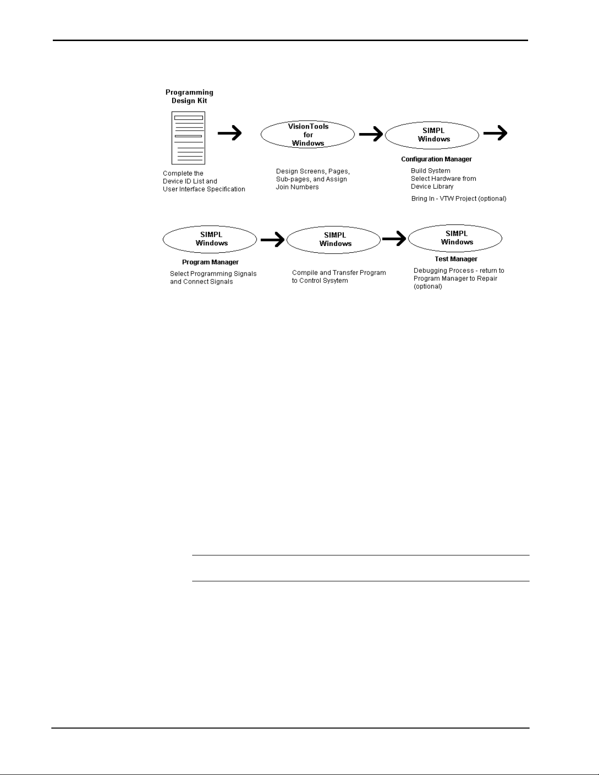
SIMPL™ Windows
Preparation
Review and Programming
SIMPL™ Windows
SIMPL Windows is Crestron Electronics development environment for
programming Crestron control systems. It provides the link between Crestron
system hardware and the whole world of equipment to be controlled
SIMPL (Symbol Intensive Master Programming Language) is an easy-to-use
programming language that is completely integrated and compatible with all
Crestron system hardware. SIMPL Windows offers drag and drop functionality in a
familiar Windows® environment.
System Design & Programming Process
Understanding the basics of Crestron system design and the steps involved in the
programming process will allow programmers to use all of the powerful features of
SIMPL Windows.
Installation & Operations Guide – DOC. 5728C Crestron SIMPL Windows • 3
Page 14
Software Crestron SIMPL™ Windows
Basic System Design Process
Crestron’s Programming Design Kit
Crestron recommends starting a control system design by taking advantage of the
equipment lists and touchpanel layout pages in the Programming Design Kit DOC.
5277.
This kit provides the necessary tools to help develop a carefully designed system by
identifying what equipment is going to be controlled and in what manner. Design
sheets allow a programmer to list all equipment and control devices. Pages for
developing sample touchscreens are also included.
The Programming Design Kit will document the equipment to be controlled, the
control protocol, and the touch screen layout. Everything the programmer needs to
start the project is listed in the Design Kit.
VisionTools™ Pro-e
VT Pro-e allows programmers to create custom designed projects for touchpanels or
web browsers. By supplying SIMPL Windows with the VT Pro-e project name,
touchpanel designs can be brought into SIMPL Windows automatically. Each
button’s join number and text will be retained. This is a great time saving feature.
NOTE: Projects created with Crestron's older product, VisionTools™ for
Windows, are also supported.
Programming Process
Once the basic system is designed on paper using the Programming Design Kit and
the touchscreens have been created in VT Pro-e, the system programmer should
review the following process.
4 • Crestron SIMPL Windows Installation & Operations Guide – DOC. 5728C
Page 15

Crestron SIMPL™ Windows Software
Identify the equipment that is going to be controlled.
Programmers should refer to the Device Identification List in the Programming
Design Kit, Job Design Specification, or other documentation that lists equipment
that is to be controlled.
Determine how the equipment is going to be controlled.
Knowing how the various pieces of equipment are going to be controlled is very
important. This will let the programmer know what control devices (Network
Module, Control Card, or other) will be necessary to control the equipment.
For example: IR control devices require a CNXIR –8 plug-in card.
Configure the system in SIMPL Windows
Configure the system by building it in the Configuration Manager. Locate the
control system in the Device Library. Drag and drop the system into the System
Views window. Complete the system configuration by adding interface devices,
network modules, control cards, and other devices. All the necessary Crestron
hardware should be included in your configuration.
Program the system in SIMPL Windows
After the system is built by adding all the necessary Crestron hardware, begin
programming the system by working in the Programming Manager. Program each
button function from the system touchpanels or other user interface devices. Begin
by naming the output signals from the user interface. Select the symbol(s) needed for
the program in the Symbol Library. Drag and drop the symbols into the Program
View window. Assign signal names to symbol inputs and outputs in the Detail View
window.
Installation & Operations Guide – DOC. 5728C Crestron SIMPL Windows • 5
Page 16

Software Crestron SIMPL™ Windows
Contact Crestron Electronics, Inc.
Telephone Numbers
If you cannot locate specific information or have questions, please take advantage of
Crestron's award winning technical support team by calling:
• In the US and Canada, call Crestron’s corporate headquarters at
1.888.CRESTRON [1.888.273.7876].
• In Europe, call Crestron International at +32.15.50.99.50.
• In Asia, call Crestron Asia at +852.2341.2016.
• In Latin America, call Crestron Latin America at +5255.5093.2160.
• In Australia and New Zealand, call Crestron at +613.9480.2999.
Email Technical Support
Use the following addresses for Crestron Email technical support:
North America
• Support U.S. East – supporteast@crestron.com
• Support U.S. Central – supportcentral@crestron.com
• Support U.S. West and Canada – supportwest@crestron.com
International
• Support Outside North America – supportintl@crestron.com
Crestron on the World Wide Web
• www.crestron.com
Trademark Information
All brand names, product names, and trademarks are the sole property of their
respective owners.
SIMPL, SIMPL+, SmarTouch, and VisionTools, are trademarks of Crestron
Electronics, Inc.
Windows is a registered trademark of Microsoft Corporation.
Windows 95/98/Me/XP and Windows NT/2000 are trademarks of Microsoft
Corporation
6 • Crestron SIMPL Windows Installation & Operations Guide – DOC. 5728C
Page 17

Crestron SIMPL™ Windows Software
®
Installing SIMPL™ Windows
System Requirements
The PC where SIMPL™ Windows is to be installed should meet these
minimum system requirements.
• Windows 98/NT/XP Operating System
• 64 MB RAM
• 100 MB hard drive space
• 450 MHz or faster Pentium processor
• 640 x 480 or higher screen resolution
Crestron Database Requirements
Crestron is continually adding the latest equipment to the Crestron Database to
ensure that the latest driver files are available. To take advantage of the latest drivers,
Crestron recommends that SIMPL Windows be used with Crestron Database
v11.7.208 or later.
From the Crestron web site, www.crestron.com
Crestron FTP form and download by following the directions provided. The Crestron
database is typically installed in C:\Crestron\CresDB.
Installing from the Crestron Web Site
From the Crestron web site, www.crestron.com, select Downloads. Complete the
Crestron ftp form and download by following the directions provided. SIMPL
Windows is typically installed in C:\Crestron\Simpl.
, select Downloads. Complete the
Installation & Operations Guide – DOC. 5728C Crestron SIMPL Windows • 7
Page 18
Software Crestron SIMPL™ Windows
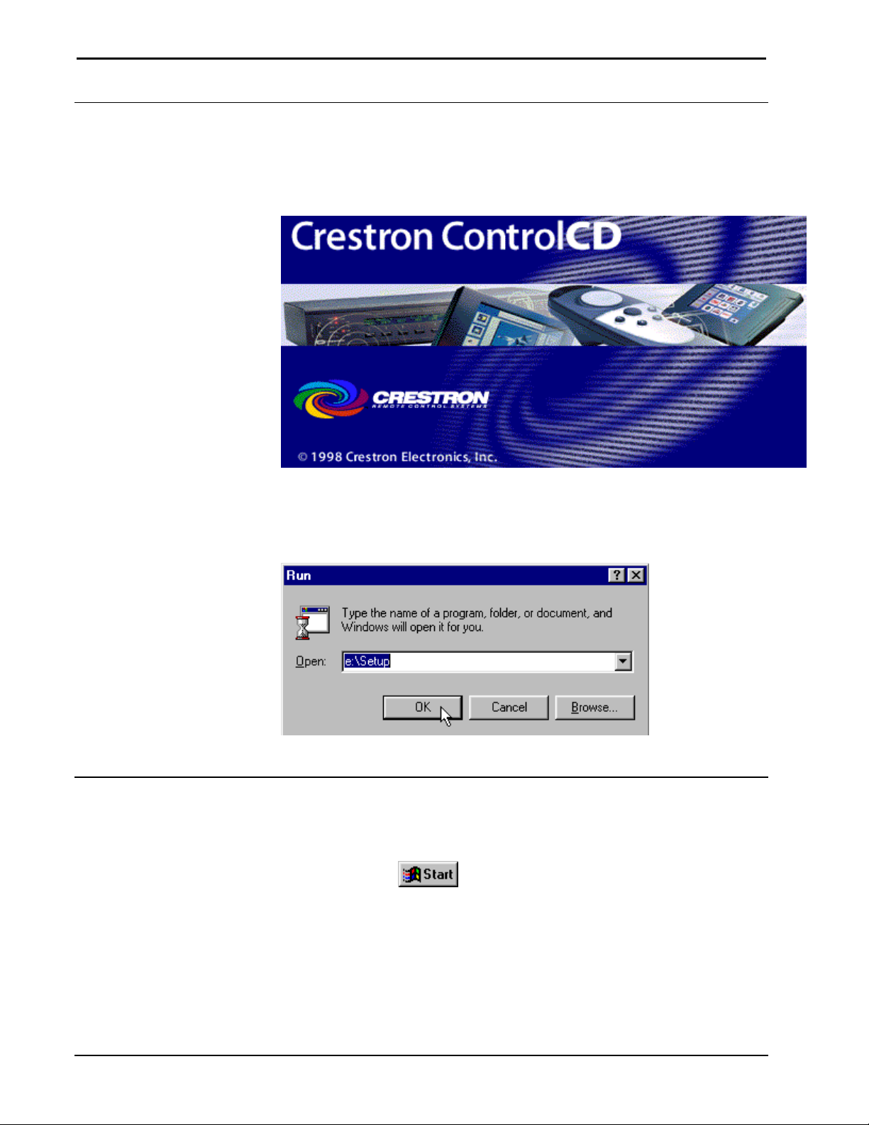
Installing from the Crestron ControlCD
The Crestron ControlCD is a design tool, packed full of all the latest software
technical information, and program examples. Contact Crestron to obtain a copy.
Crestron ControlCD
Insert the Crestron ControlCD into the PC's CD ROM drive and select Run…from
the Windows start menu. Type the letter for the CD-ROM drive and :\Setup.
Follow the directions provided.
Run…Dialog Box
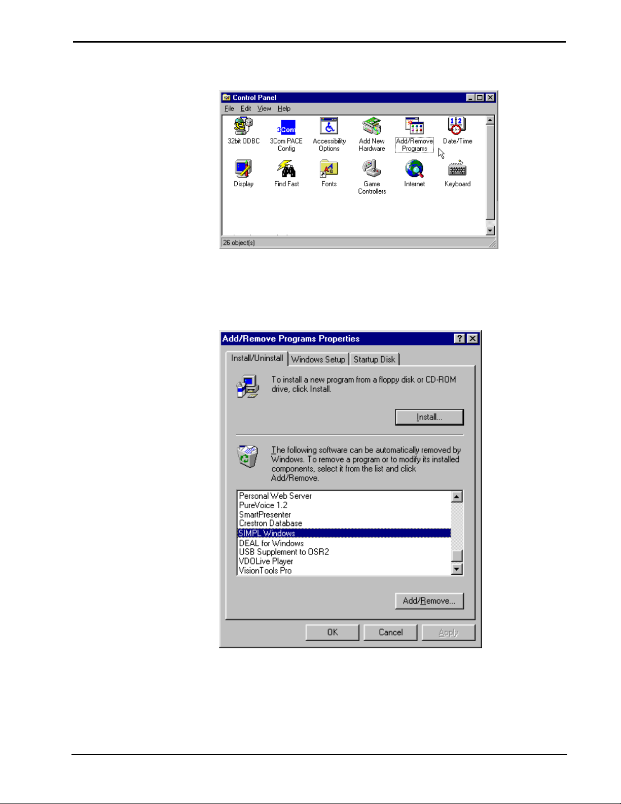
Uninstall SIMPL™ Windows®
Follow the procedure in this section to remove SIMPL™ Windows from your hard
drive.
Select the Windows
8 • Crestron SIMPL Windows Installation & Operations Guide – DOC. 5728C
button and choose Settings | Control Panel.
Page 19
Crestron SIMPL™ Windows Software
Select Add/Remove
Select "Add/Remove Programs". The "Add/Remove Programs Properties" dialog
box is displayed. Select SIMPL Windows and click on the Add/Remove… button.
Add/Remove Programs Dialog Box
Installation & Operations Guide – DOC. 5728C Crestron SIMPL Windows • 9
Page 20

Software Crestron SIMPL™ Windows
This page intentionally left blank.
10 • Crestron SIMPL Windows Installation & Operations Guide – DOC. 5728C
Page 21

Crestron SIMPL™ Windows Software
DOS Workshop
Migration to SIMPL Windows
Crestron has been working hard to develop easy-to use Windows-based programs for
our customers. The link between Crestron systems hardware, panels, and controlled
devices is Crestron software. The design and programming tools (VisionTools™
Pro-e and SIMPL™ Windows) are a unified and integrated software package that
works with all Crestron hardware.
Design the touchpanel with the integrated graphics tool, VT Pro-e. VT Pro-e gives
programmers the best of both worlds allowing custom touchpanels and push button
panels to be designed and programmed. Create the “intelligence” of the system with
SIMPL Windows; Crestron’s Windows-based, 32-bit, drag-n-drop software. SIMPL
Windows can integrate your touchpanel designs (created in VT Pro-e), automatically
naming signals to match the button functions.
Crestron Electronics has been hard at work developing and integrating its software.
SIMPL Windows retains the methodology of Cresnet II Workshop and incorporates
many new features. SIMPL Windows is compatible with all our current control
systems. SIMPL Windows is the only programming software for Crestron’s
generation CNX line of control systems.
Changes from Workshop
SIMPL Windows is a Windows®-based program that takes advantage of Windows
easy-to-use functions such as multiple windows and drag and drop functionality
throughout the program.
SIMPL Windows includes several powerful features to help programmers make the
transition from the Cresnet II Workshop. New users will find them helpful, as well.
Symbol CrossReference
Symbol names have been changed to be more descriptive and easier to remember.
Typing the DOS Workshop name in SIMPL Windows will still work too. The
Symbol CrossReference chart will help programmers easily learn the new names for
device and logic symbols. The Symbol CrossReference lists the exact equivalence
between the old Workshop and new SIMPL Windows symbol names.
Installation & Operations Guide – DOC. 5728C Crestron SIMPL Windows • 11
Page 22

Software Crestron SIMPL™ Windows
SpeedKey
Users of the DOS Workshop are familiar with many of the previous symbol names.
This knowledge works to the programmer’s advantage in SIMPL Windows, in the
form of the SpeedKey feature. This option allows you a quick and easy method for
inputting symbols into your program.
Workshop users who are familiar with the names of their most-often-used symbols
can key them very quickly, hence the name SpeedKey. SpeedKey will let
programmers enter Workshop symbol names when building the program; SIMPL
Windows will then insert the new symbol name for you automatically, placing each
symbol or symbol subsystem directly into the Logic folder, as if it was manually
dragged there with the mouse. As each symbol name is typed it appears on the Status
Bar. As long as the Logic folder in Program View is highlighted, you can add old or
new symbol names, with no case sensitivity.
KeyCombo Shortcut Table
The following table provides a convenient list of all keyboard and function-key
shortcuts for the SIMPL Windows Programming Manager. Each entry in the table on
the next page lists a keyboard shortcut, and the result it produces.
12 • Crestron SIMPL Windows Installation & Operations Guide – DOC. 5728C
Page 23

Crestron SIMPL™ Windows Software
(
)
(
)
(
)
(
)
y
Keyboard Combination
F1
F3
SHIFT-F4
F4
F5
F6
F7
F8
SHIFT-F8
ALT- PLUS
ALT-MINUS
ENTER
ALT-SHIFT-PLUS
SHIFT-HOME
SHIFT-END
SHIFT-CLICK
DELETE
CONTROL-DELETE
ALT-1
ALT-2
ALT-3
ALT-4
ALT-5
ALT-6
ALT-C
ESCAPE
TAB or Arrow Ke
POWR/sequence
CONTROL-T
CONTROL-N
CONTROL-M
CONTROL-O
CONTROL-S
CONTROL-P
CONTROL-X
CONTROL-C
CONTROL-V
CONTROL-SHIFT-V
CONTROL-Z
CONTROL-F
CONTROL-E
CONTROL-SHIFT-E
CONTROL-F4
ALT-Y
ALT-P
ALT-B
"+"
"-"
twice
"+"
s
Description or Result
Bring Up Context-Sensitive Help.
Find next Symbol
Assign sequential names to highlighted Signals,
based on first Signal
Assign sequential names to highlighted Signals,
based on last Signal
Refresh window
Copy Input Signal to its Output, or vice-versa
Resize a Symbol (Detail View)
Next pane
Previous pane
Adds Inputs and/or Outputs one at a time
Removes Inputs and/or Outputs one at a time
Create new Signal name.
Add Inputs or Outputs in specified multiples
Select Inputs or Outputs in an upward direction,
from present cursor position to first Input or
Output.
Select Inputs or Outputs in a downward
direction, from present cursor position to last
Input or Output.
Select a variable range of Inputs or Outputs
Delete a Signal or Symbol
Delete a Signal, and highlight the Input or
Output below it
Add theSignalSuffix set in Prefs
Add theSignalSuffix set in Prefs
Add theSignalSuffix set in Prefs
Add theSignalSuffix set in Prefs
Add theSignalSuffix set in Prefs
Add a SignalSuffix when prompted
Communications
Cancels Edit Mode
Moves cursor between Inputs and Outputs
Result depends on particular combination of
keyboard shortcuts used.
Start
Create a new program
Create a new macro
Open a program or macro
Save a program or macro
Print
Cut
Copy
Paste
Paste Special
Undo
Find Symbol
Expand current node
Collapse current node
Close Detail View
Symbol Library
Program View
Toggle Both Views
Installation & Operations Guide – DOC. 5728C Crestron SIMPL Windows • 13
Page 24

Software Crestron SIMPL™ Windows
g
g
V
g
g
g
r
y
g
g
Feature Comparison
The Feature Comparison table presents a list and a brief description of the popular
Workshop feature and the corresponding SIMPL Windows function.
Workshop/SIMPL Windows Comparison Table
DOS Workshop SIMPL Windows
Programming Language
SIMPL I SIMPL
Symbol Names
Short, non-descriptive symbol
names
Viewing Symbols
While programming: can only
view one Symbol at a time
ram Testing
Pro
Test program by exiting DOS
Workshop and opening debugger
Enterin
Text, variables, and other
information was entered
character by character into fields
isionTools for Windows
DOS Workshop and VisionTools
for Windows completely separate
programs
Modem Database
Adequate modem database Extensive modem database in
Pro
N/A Symbols can now be clustered
Si
Less consistent approach to
signal inputs/outputs
Si
N/A Signals color coded: Digital=Blue;
Information
ram Subsystems
nal Representation
nal Type Identifie
New self explanatory symbol
names
While programming: can view
multiple symbols
Test Manager is now called from
the program; no longer have to
leave the development tool to test
and debug
Windows drag and drop style &
copy/paste shortcuts
SIMPL Windows integrates with
VisionTools for Windows and
imports VTW projects
ViewPort: can set strings, etc.
and grouped for easy location
and manipulation
Signal inputs on left, Outputs on
right
Analog=Red; Other=Black
Test Environment
SAM - Monitors digital signal
activity
Indirect Text
Programming handled using
separate SDPM S
nal Name Length
Si
Signal name table would fill up,
names had to be shortened to fit
Communicatin
N/A Pass Thru Mode in ViewPort
14 • Crestron SIMPL Windows Installation & Operations Guide – DOC. 5728C
mbol.
with User Devices
Test Manager - Monitors digital,
analog, and serial signal activity
Easy to program, handled as part
of the TouchPanel
No limit to signal name length.
allows communication with User
Devices
Page 25

Crestron SIMPL™ Windows Software
Importing Workshop Programs
Workshop programs can be imported to SIMPL Windows by turning them into a
macro, importing, and converting back into a program. This requires removing all
devices before turning the program into macro. In SIMPL Windows, import the
macro and replace the devices that were removed.
1. Make a backup copy of the Workshop program.
2. In Workshop, remove all the net devices, convert to a CNRACK, and delete all
the plug-in cards.
NOTE: If the original Workshop program contained macros, SIMPL Windows will
remove any indication of the macros and install all of the code that used to be within
the macros directly into the program. This can become a very tedious when
importing large programs. To preserve macros, import them separately into SIMPL
Windows by following steps 3-5 for each macro.
3. Install a GENERIC symbol in the Workshop program. In the comment section
type “PLACEHOLD”. This symbol will act as a placeholder for the macros
signal names.
4. Comment out the Workshop macro so it does not convert by selecting Alt+F1.
5. Transfer the signal names of the macro to the PLACEHOLD symbol. List the
signal names in the following format:
Output_1,
Output_2,
Output_3;
Input_1,
Input_2;
(Signal names are followed by a coma. The last signal either
output or input, is followed by a semicolon)
6. Install a DEFARGS symbol to make the program into a macro, then convert the
program, a ".imc" file will be produced. Workshop will remind user’s that there
are incomplete symbols and commented out symbols. This is acceptable, click
Yes.
7. Start SIMPL Windows, choose File | Import a Workshop Macro.
8. Choose File | Convert To Program to complete the transfer.
9. Save the program by selecting File | Save. Replace the net devices and connect
the necessary signals.
10. In SIMPL Windows select File | Import a Workshop Macro. Import the
Workshop macro that was previously commented out. Save the macro as a User
Macro in SIMPL Windows.
11. Select the new User Macro from the SIMPL Windows Symbol Library and drag
it into the imported program.
12. In the imported program copy the signal names from PLACEHOLD symbol to
the new User Macro.
Installation & Operations Guide – DOC. 5728C Crestron SIMPL Windows • 15
Page 26

Software Crestron SIMPL™ Windows
This page intentionally left blank.
16 • Crestron SIMPL Windows Installation & Operations Guide – DOC. 5728C
Page 27

Crestron SIMPL™ Windows Software
SIMPL™ Windows®– Getting Started
SIMPL Windows Applications
SIMPL™ Windows is an all-encompassing application. It is comprised of several
individual applications that interact to help users design, build, and program control
systems.
SIMPL Windows's main applications are Configuration Manager, Program Manager,
Test Manager and ViewPort. SIMPL Windows also integrates with Crestron’s user
interface design software, VisionTools™ Pro-e.
Installation & Operations Guide – DOC. 5728C Crestron SIMPL Windows • 17
Page 28
Software Crestron SIMPL™ Windows
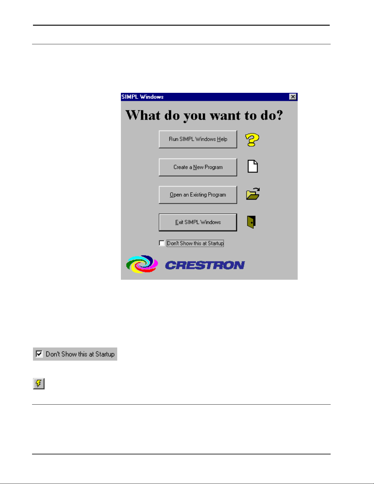
Opening SIMPL Windows
Each time SIMPL Windows is opened the “Quick Access Window” appears and
prompts users to select the first task.
Quick Access Window
The window asks you: "What do you want to do?" and presents four options:
1. Run SIMPL Windows Tutorial
2. Create a New Program
3. Open an Existing Program
4. Exit SIMPL Windows
Removing the QuickAccess Window
To remove the QuickAccess window, select the Don’t show this at startup box at the bottom
of the window and close the window.
Call Up the QuickAccess Window
QuickAccess Icon
Users can call up the QuickAccess window at any time during your program by clicking the
Lightning Bolt icon on the SIMPL Windows button bar, or selecting File | Start.
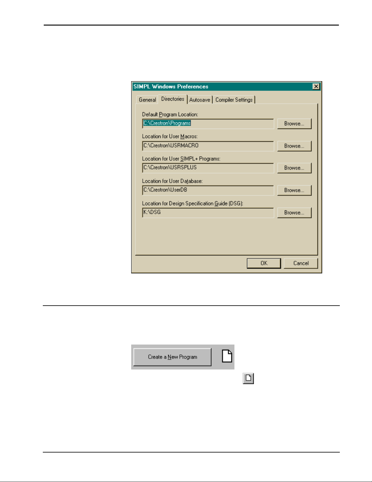
Set Directory Paths
The install process sets the directory paths, but it is important to make sure the paths
are correct after SIMPL Windows is loaded into your PC.
18 • Crestron SIMPL Windows Installation & Operations Guide – DOC. 5728C
Page 29
Crestron SIMPL™ Windows Software
Select Edit | Preferences…
This will display the “SIMPL Windows Preferences" window. Select the Directories
tab and make sure the directory paths are correct.
SIMPL Windows Preferences Dialog Box
Click OK when all paths are correct. The system will pause for approximately thirty
seconds while information is reloaded.
Create A New Program
New programs can be started in a variety of ways including:
Selecting Create a New Program from the QuickAccess Window.
Selecting New Program from the button bar.
Selecting File | New Program.
Installation & Operations Guide – DOC. 5728C Crestron SIMPL Windows • 19
Page 30
Software Crestron SIMPL™ Windows
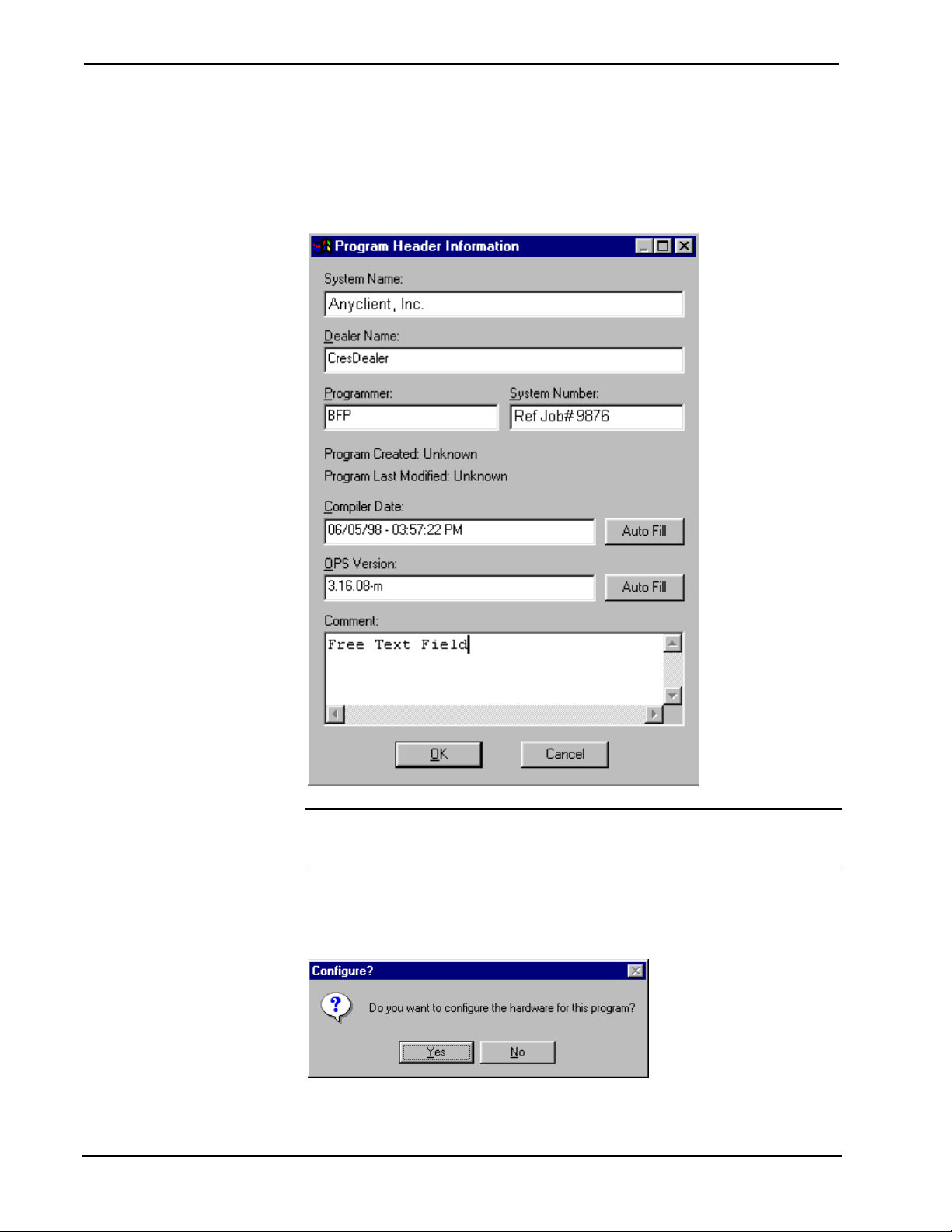
Program Header
When a new program is started the "Program Header Information" window appears.
It is important to complete all the information, as it will be printed out on the
connection sheet.
"Program Header Information" Window
NOTE: Information entered into the Dealer Name and Programmer fields of the
"Program Header Information" dialog box are recalled from program to program
until SIMPL Windows is reloaded or upgraded.
After the "Program Header Information" dialog box is complete, click OK. SIMPL
Windows will ask if you want to configure the hardware for the system.
Configure? Window
Click Yes to display the Configuration Manager.
20 • Crestron SIMPL Windows Installation & Operations Guide – DOC. 5728C
Page 31

Crestron SIMPL™ Windows Software
Configuration Manager
Accessing Configuration Manager
Configuration Manager is where programmers will “build” the control system by
selecting hardware from the Device Library. Configuration Manager can be opened
several different ways.
Configuration Manager
Opening Configuration Manager for a New Program
After a new program is started and the program header has been completed, SIMPL
Windows will display the “Configure?” window.
Configure? Window
Click Yes to open Configuration Manager.
Open Configuration Manager from Project Menu
To open Configuration Manager from the SIMPL Windows menus, select Projects |
Configure System.
Open Configuration Manager from Button Bar
Select the Configuration Manager button from the SIMPL Windows button bar.
Installation & Operations Guide – DOC. 5728C Crestron SIMPL Windows • 21
Page 32

Software Crestron SIMPL™ Windows
Configuration Manager Navigation
The Configuration Manager consists of four separate view windows (three of which
are sub-windows of System Views).
Configuration Manager Main Window
Device Library
The Device Library is the master list of hardware components available to “build”
your control system. This list of devices allows programmers to select the hardware
and drag and drop it into the Network System View. These components, or devices,
are grouped functionally by device type. Expand the folder for the device you require
by clicking on the plus sign (collapse the folder by clicking the minus sign).
Device Library groups, with a brief explanation of each:
• Control Systems: The "brain" of each Crestron system; a Control
System contains the microprocessor, runs the operating system,
and executes the SIMPL Windows program.
• Ethernet Control Modules: This refers to the Ethernet expansion
cards.
• Expansion Module: This refers to the Crestron CNIORACK, a
device used to expand the functionality of the CNRACK by
providing for use of additional cards.
• Lighting: Various devices that make up lighting systems, all of
which connect to the Cresnet network.
22 • Crestron SIMPL Windows Installation & Operations Guide – DOC. 5728C
Page 33

Crestron SIMPL™ Windows Software
• Local Control Panels: Plug-in cards that provide a button panel to
a Control System.
• Network Control Modules: Devices that connect to the Cresnet
network. Usually external devices.
• Plug-in Control Cards: Circuit boards that plug-in to an empty
card slot in a control system or other device. Cards provide
additional capability to a system.
• Plug-in Control Cards (CNX Series): Plug-in cards compatible
with Crestron generation X line of control systems.
• Plug-in DPA Modules (CNX Series): Plug-in cards provide Direct
Processor Access.
• Serial Drivers (General): General one or two-way serial devices
that require the user to provide string input and output information.
Use one of these devices if yours is not listed in the Crestron
Database.
• Power Supplies: Used to power your Cresnet network; it is
common to need multiple power supplies for a given system. It is
not necessary to add power supplies to the program. The power
supply symbols are included for documentation purposes such as
the Connection Sheet.
• Touchpanels (Wired): Cresnet-compatible touchpanels.
• Touchpanels (Wireless): RF touchpanels, one-or two-way, which
do not go on a Cresnet network, but require a wireless RF receiver
(see below).
• Wired Panels: User interface such as a button panel, that your end
user interacts with to control their Cresnet system.
• Wireless Receivers (IR): IR receivers used with IR transmitters.
• Wireless Receivers (RF): RF receivers used with RF transmitters
or RF touchpanels.
• Wireless Remotes (IR): IR transmitters.
• Wireless Remotes (RF): RF transmitters.
• User Devices: If your device is not in the Crestron or User
databases and you want to program the device yourself in detail.
• Crestron DB: Information about controlled devices Crestron
knows how to program; listed by device type, manufacturer, and
model. Crestron updates this database periodically; check your
version number to determine whether you have the latest installed.
• User DB: A place to store information about controlled devices
that have been created; and are not yet supported by Crestron. We
encourage programmers to send information on these devices to
Crestron so that they can be included in the next release of the
Crestron Database. The Database has thousands of driver files. We
want to be able to support as many devices as possible and
welcome your additions.
Installation & Operations Guide – DOC. 5728C Crestron SIMPL Windows • 23
Page 34

Software Crestron SIMPL™ Windows
Network System View
When Configuration Manager is opened, Network System View prompts the user to
begin by displaying the message:
"Start by dropping a Control System here…".
Network System View is where programmers start to “build” the system by dragging
over a control system from the Device Library.
Configuration Manager-Network Systems View
Network System View allows programmers a graphical representation of the entire
physical system. Programmers will see the back of the control system, including
empty card slots and built-in card slots. Network device icons (Cresnet and Ethernet)
are displayed in the space below the system. It may be necessary to use the scroll
bars to see all the network devices.
Detail System View
Detail System View offers the ability to display a graphical view of each module in
the control system. Select the module or port to display its configuration information.
Detail System View – CNXTVC-3 Module Configuration
System Device Tree
-TBD-
24 • Crestron SIMPL Windows Installation & Operations Guide – DOC. 5728C
Page 35

Crestron SIMPL™ Windows Software
Configuration Manager Button Bar
The Configuration Manager Button Bar allows short cuts with only one mouse click.
Configuration Manager Button Bar
Start
Start – "QuickAccess"
Window
New Program
Open
Save
The lightning bolt icon will display the "QuickAccess" window.
New Program
New Program button will begin new programs with the "Program Header
Information" window.
Open Program
The open folder icon will open an existing program.
Save Program
The floppy disc icon is a shortcut for save. It will save the current program.
Program Manager
Configuration Manager
Convert/Compile
Transfer Program
ViewPort
Test Manager
Help
Program Manager
Program Manager button switches current program to Program Manager for
programming activities.
Configuration Manager
Configuration Manager button switches current program to Configuration Manager
for system building activities.
Convert/Compile
Convert / Compile checks the program for errors and compiles.
Transfer Program
Transfer Program icon transfers program to the control system.
ViewPort
ViewPort button launches the SIMPL Windows ViewPort.
Test Manager
Test Manager button tests and debug program. Realtime monitoring of signal
activity.
Help
This button displays the SIMPL Windows help files.
Installation & Operations Guide – DOC. 5728C Crestron SIMPL Windows • 25
Page 36

Software Crestron SIMPL™ Windows
Configuring the System
The way systems are “built” is by dragging hardware from the Device Library and
dropping it into Network Systems View. Start with a control system and add the
necessary devices. The system devices should be identified in the design
specification or the Device List from the Programming Design Kit. Refer to the
Crestron ControlCD for compatibility and specifications.
Selecting Hardware
Locate the necessary hardware by opening the folder that contains the component.
Open the folder by clicking on the plus (+) sign. Highlight the device you want by
clicking on it. Drag it to the Network System View area by holding down the left
mouse button while dragging the device. Release the mouse button to drop the
device.
Selecting Control System
Once a control system is chosen it will always be displayed in the Network System
View. The next step is to add the other devices that comprise the system such as
network devices and additional plug-in cards. Macros for controlling hundreds of
different pieces of equipment are available in the User Devices folder under Crestron
Database. Crestron continually updates this database to include the latest macros.
26 • Crestron SIMPL Windows Installation & Operations Guide – DOC. 5728C
Page 37

Crestron SIMPL™ Windows Software
Control System Ready for Additional Hardware
SIMPL Windows guides programmers through the building process by continuously
providing feedback via the cursor. SIMPL Windows will not allow programmers to
install devices that are not compatible with the control system or other installed
components. The incompatibility is communicated to the user when the cursor turns
into a circle with a strike through it. SIMPL Windows will not allow a drop when the
cursor in this state.
Cursor Displaying an Impossible Drop
When SIMPL Windows displays the cursor as the standard pointer with an added
plus (+) sign, this is representative of a legal drop with full compatibility.
Installation & Operations Guide – DOC. 5728C Crestron SIMPL Windows • 27
Page 38

Software Crestron SIMPL™ Windows
Cursor Displaying a Compatible Drop
Replacing Devices
Devices are replaced by selecting a new device, dragging it into Network System
View, and dropping it on the device to be replaced.
Replace CNRACK with CNMS
SIMPL Windows will ask users to verify that a device is to be deleted. Click the
appropriate button.
Replace Device Confirmation
Configure System Control Devices
System control devices include plug-in control cards, network devices (NetDevices)
and drivers. These are system devices that control the A/V components and other
equipment.
Plug-in Control Cards
Plug-in control cards are added to a control system in the Configuration Manager.
Select the plug-in card from the Device Library and drop it into an open card slot in
the control system.
28 • Crestron SIMPL Windows Installation & Operations Guide – DOC. 5728C
Page 39

Crestron SIMPL™ Windows Software
Selecting Control Cards
Configuration Manager will display the card in the slot it was dropped into. By
clicking the right mouse button, users can delete the card or configure. For this
example, choose Configure.
Configure Plug-in Cards
After selecting Configure, the “Device Settings” window is displayed. Several
parameters of control cards can be configured. The Name tab allows users to change
the name for easy identification (especially if multiple cards are used). The card slot
number can be changed under the Card Slot tab. The Connection Sheet tab allows
users to provide notes that will be printed on the connection report.
Installation & Operations Guide – DOC. 5728C Crestron SIMPL Windows • 29
Page 40

Software Crestron SIMPL™ Windows
Device Settings – CNXVTC-3
NetDevices
These devices are configured in the Configuration Manager. Select the system
control device and drag it into the control system. For this example a CT-3000
touchpanel is dropped into the NetDevices slot.
Drop Network Devices into the NetDevice Slot
Configuration Manager will display network devices as icons under the control
system. Users may have to use the scroll bars to view all the icons. Three CT-3000
touchpanels have been added for this installation.
30 • Crestron SIMPL Windows Installation & Operations Guide – DOC. 5728C
Page 41

Crestron SIMPL™ Windows Software
Display of all NetDevices
The NetDevices can be configured or deleted by selecting the icon and clicking the
right mouse button.
Configure NetDevices
After selecting Configure, the “Device Settings” dialog box for the NetDevice will
be displayed. Several parameters of the NetDevice can be configured.
Name
The name can be changed under the Name tab (this is recommended if there is more
than one NetDevice of the same type). The Device Name tab also shows device
power consumption in watts.
Device Settings: Device Name Tab
Installation & Operations Guide – DOC. 5728C Crestron SIMPL Windows • 31
Page 42

Software Crestron SIMPL™ Windows
Net ID
The Net ID tab displays the network ID of the particular NetDevice.
Device Settings: Net ID Tab
UI Project (for touchpanels only)
The UI Project tab refers to the User Interface Project Name as given in
VisionTools™ Pro-e. Touchpanel designs from Crestron’s VT Pro-e software can be
referenced and brought into the SIMPL Windows program. Join numbers and
buttons are brought in when a UI project is specified. This feature can save an
enormous amount of typing and referring back and forth between VT Pro-e and
SIMPL Windows.
Device Settings: UI Project Tab
Chain (for touchpanels only)
NetDevices can be chained together under the Chain tab. Chaining means that
multiple touchpanels are programmed exactly the same. One touchpanel acts as a
‘master’ to which the others are chained.
Begin to chain by selecting one of the ‘slave’ touchpanels. Under the right mouse
menu click Configure and select the Chain tab. Select the Net ID of the ‘master’
panel.
32 • Crestron SIMPL Windows Installation & Operations Guide – DOC. 5728C
Page 43

Crestron SIMPL™ Windows Software
Device Settings: Chain Tab – Select Master
After all the ‘slave’ panels have the ‘master’ Net ID set, select the ‘master’
touchpanel and view the Chain Tab. The Chain tab for the ‘master’ displays all the
Net Ids that are chained to it.
Device Settings: Chain Tab – Display Slaves
The device icons will appear with chains across them. This is the visual confirmation
that a touchpanel is chained to a ‘master’ panel.
Chained Touchpanels (04, 05) with Master (03)
Connection Sheet
The Connection Sheet tab allows free text to be entered with other helpful
descriptions. These notes are printed on the connection report.
Installation & Operations Guide – DOC. 5728C Crestron SIMPL Windows • 33
Page 44

Software Crestron SIMPL™ Windows
Device Settings: Connection Sheet Tab
Configure User Devices
User devices include CD players, VCRs, lighting controls and anything else the end
user interfaces with through the Crestron control system. These are usually the
devices that are being controlled.
Configuring an IR Controlled Device
Example (SONY CPC-303ES CD player)
Once installed, devices will need to be configured. For example, a device such as a
SONY CPC-303ES CD player is controlled with IR signals. The control system
specified for our design is a CNMSX-PRO which has a CNXIR-8 control card
installed from the factory. The CNXIR-8 is an IR card that has eight serial ports
available. Click on the CNXIR-8 to display the eight serial ports in Detail
SystemView.
Network View of CNMSX-PRO (top), Detail System View of CNXIR-8 (bottom)
Select the equipment to be controlled by the IR port A. In this example an IR driver
file for a SONY CCP-303ES CD player is selected from the Crestron Database. The
34 • Crestron SIMPL Windows Installation & Operations Guide – DOC. 5728C
Page 45

Crestron SIMPL™ Windows Software
database is located in the User Devices folder of the Device Library. Click and drag
the SONY CCP-303ES and drop it into IR Port A of the CNXIR-8 control card.
Select Equipment to be Controlled and Drop into Appropriate Control Port
Right mouse click on the equipment to configure the device settings or delete the
device. For this example, select Configure.
Right Click to Configure or Delete
When Configure is selected the “Device Settings” window will be displayed. The
Device Settings dialog box allows the programmer to configure several parameters
of each user device, as well as record notes for the connection sheet report.
Device Settings Window
Installation & Operations Guide – DOC. 5728C Crestron SIMPL Windows • 35
Page 46

Software Crestron SIMPL™ Windows
Example-Serial Driver Configuration
Much of the equipment in the A/V industry is controlled by serial communication
standards like RS-232, RS-422, and RS-485 for example. The control system
specified for our design is a CNMSX-PRO which has a CNXCOM-6 control card
installed from the factory. The CNXCOM-6 is a two-way serial card that supports
RS-232, RS-422, and RS-485. Click on the CNXCOM-6 to display the six serial
ports in Detail System View.
Network System View of CNMSX-PRO (top), Detail System View of CNXCOM-6 (bottom)
Some serial cards may have a default driver already installed. If this is not the
preferred drive, replace it by selecting another driver. Select the serial driver from
the Device Library. In this example a ST-COM/CNXCOM two-way serial driver is
selected. Click and drag the ST-COM/CNXCOM and drop it into Port A of the
CNXCOM-6 control card.
Select Serial Driver to be Installed and Drop into Appropriate Control Port
Right mouse click on the driver to configure the device settings or delete the device.
For this example, select Configure.
36 • Crestron SIMPL Windows Installation & Operations Guide – DOC. 5728C
Page 47

Crestron SIMPL™ Windows Software
Right Click to Configure or Delete
When Configure is selected the “Device Settings” window will be displayed. The
Device Settings dialog box allows the programmer to configure certain parameters of
each device, as well as record notes for the connection sheet report. Serial Devices
have an additional tab for Serial Settings. Baud Rate, Data Bits, Stop Bits, Parity,
Communication Standard, and Handshaking are all configured in the Serial Settings
tab. For the default settings simply click OK.
Device Settings Window
Installation & Operations Guide – DOC. 5728C Crestron SIMPL Windows • 37
Page 48

Software Crestron SIMPL™ Windows
Deleting Devices
Devices can be deleted from Configuration Manager by selecting them and clicking
the right mouse button. Configuration Manager will display a choice box in which
you can choose either Configure or Delete.
Deleting a NetDevice
Configuration Manager will ask if you are sure that you want to delete the selected
device.
Delete Prompt
Users can also delete devices from the Configuration Manager’s System Device Tree.
SIMPL Windows displays a delete confirmation box. Select the appropriate button.
Confirming Deletion via the Device List
Automatically Configure Devices
The SIMPL Windows feature AutoFill automatically configures certain types of
devices. AutoFill automatically detects control system devices on your Cresnet
network, then configures your system, eliminating the need for programmers to
manually configure these devices in Configuration Manager.
38 • Crestron SIMPL Windows Installation & Operations Guide – DOC. 5728C
Page 49

Crestron SIMPL™ Windows Software
To Use AutoFill
To initiate Auto Fill, select Project | Auto Fill Rack.
It is important to remember that AutoFill cannot detect transmitters (IR nor RF) or
one-way RF wireless touchpanels such as the ST-1550 (although it will detect
two-way wireless touchpanels); nor does it detect User Devices. Therefore, after
using AutoFill, make sure to manually configure these kinds of devices in the
Configuration Manager.
NOTE: Your system must first be physically connected to your PC before initiating
AutoFill.
Importing VisionTools™ for Windows and
VisionTools™ Pro-e Projects
Select the touchpanel for which you want to import a VisionTools project. Click the
right mouse button and select Configure.
Select TouchPanel for VisionTools Project
The “Device Settings” dialog box will be displayed. Select the UI Project tab and
click the Browse button to display the VisionTools project files. SIMPL Windows
supports both .prj (VTW) and .vtp (VT Pro-e) files.
Browse for VisionTools Project
Installation & Operations Guide – DOC. 5728C Crestron SIMPL Windows • 39
Page 50

Software Crestron SIMPL™ Windows
The Browse button will display a window where you can browse for a specific
project file. Select the .prj (VTW) or .vtp (VT Pro-e) file and click Open.
Select VisionTools Project
Verify that the Project path is correct and click OK.
Verify VisionTools Project Path
This process will load the VisionTools project and automatically create touchpanel
buttons, label signal names, and assign join numbers already specified in the
VisionTools project. This will become evident when the touchpanel is viewed in
Program Manager.
NOTE: This is not a “live” link to VisionTools software. The touchpanel buttons,
signal names, and join numbers are brought in when the UI project is specified. It
does not actively update.
40 • Crestron SIMPL Windows Installation & Operations Guide – DOC. 5728C
Page 51

Crestron SIMPL™ Windows Software
Default Logic from Crestron Database
Some driver files in the Crestron Database have a built-in logic. If one of these
drivers is selected and dropped into a card port, Configuration Manager will display
a Default Logic window.
Default Logic Window
The window asks if programmers want to load the default logic for the device.
Additionally, the window may contain notes and recommendations depending on the
particular device. Click Yes to load logic or No to load the device only.
Installation & Operations Guide – DOC. 5728C Crestron SIMPL Windows • 41
Page 52

Software Crestron SIMPL™ Windows
This page intentionally left blank.
42 • Crestron SIMPL Windows Installation & Operations Guide – DOC. 5728C
Page 53

Crestron SIMPL™ Windows Software
Program Manager
Accessing Program Manager
Program Manager is where programmers will “program” the control system by
selecting symbols from the Symbol Library. Program Manager can be opened several
different ways.
Opening Program Manager for a New Program
After a new program is started and the program header has been completed, SIMPL
Windows will display the “Configure?” window.
Configure? Window
Click No to skip the configuration process and go directly to Program Manager.
NOTE: Crestron recommends that programmers new to SIMPL Windows should
begin by building the system in Configuration Manager before programming in the
Program Manager.
Open Program Manager from Project Menu
To open Configuration Manager from the SIMPL Windows menus, select Projects |
Program System.
Open Program Manager from Button Bar
Program Manager
Installation & Operations Guide – DOC. 5728C Crestron SIMPL Windows • 43
Select the Program Manager button from the SIMPL Windows button bar.
Page 54

Software Crestron SIMPL™ Windows
Screen Navigation
The Program Manager consists of three main viewing windows.
Program Manager
Due to the architecture of the
Symbol Library, it is sometimes
referred to as the Symbol Tree.
Symbol Library
The Symbol Library is a master list of every symbol and macro available for use in
creating your control system program. The symbols are grouped by symbol type
with each group is contained in its own folder. The folders are expanded by clicking
on the plus (+) sign.
44 • Crestron SIMPL Windows Installation & Operations Guide –DOC. 5728C
Page 55

Crestron SIMPL™ Windows Software
The three main folders are Logic Symbols, Crestron Macros, and User Macros.
Symbol Library
Program View
Program View provides a tree type view of the program. Symbols that are selected
from the Symbol Library are dropped into the Logic folder in Program View. The
folders can be expanded/collapsed by clicking on the plus/minus (+/-) sign.
Typical Program in Program View
Installation & Operations Guide – DOC. 5728C Crestron SIMPL Windows • 45
Page 56

Software Crestron SIMPL™ Windows
The Signal List folder does not expand. Instead, double click on the folder to open
the "Signal List" dialog box, shown below. This dialog box allows the user to search
for, sort, and obtain routing details for selected signals.
"Signal List" Dialog Box
Search for a signal by entering its name in the What to Find field. If only a portion of
the name is known, the search can be narrowed by entering the root-portion of the
name in the What to Find field and selecting either the Find First or Find Next
buttons to navigate to the desired signal.
Use the "Signal List" Dialog Box to Search for a Signal
Sort the signals in the project by type. There are five options in the Show Signals of
Type area, shown after this paragraph. A checked type results in a list of type-
specific signals. More than one type can be checked. Of course, minimizing the types
checked reduces the list of signals.
46 • Crestron SIMPL Windows Installation & Operations Guide –DOC. 5728C
Page 57

Crestron SIMPL™ Windows Software
Show Signals of Type Field in the "Signal List" Dialog Box
Select a signal from the list and click on the Details button at the top right corner of
the dialog box to reveal the "Signal Detail for…" dialog box. Refer to the Signal
Routing paragraph in the Programming Features chapter for routing details.
Clicking the Details Button on the "Signal List" Dialog Box
Detail View
Detail View displays devices and symbols so the input and output signals are visible.
This is where programmers will name input/output signals.
There are several ways to display a device or symbol in Detail View. The most
common methods are:
Drag and drop the symbol from Program View
Double click on the symbol while in Program View
Detail View of Analog Ramp Symbol
Bookmark
Bookmarks are a terrific time saving way to mark certain symbols in Detail View.
When a certain cluster of symbols in Detail View is important and may have to be
referred to many times while writing the program, a bookmark should be added.
Select Bookmark | Add. SIMPL Windows will display the "Enter New Bookmark
Name" window and ask for the new bookmark name.
Installation & Operations Guide – DOC. 5728C Crestron SIMPL Windows • 47
Page 58

Software Crestron SIMPL™ Windows
"Enter New Bookmark Name" Window
Enter a bookmark name and select OK. The bookmark will be added. Anytime it is
necessary to return to the Detail View that was displayed when the bookmark was
added, select Bookmark | bookmark name.
World View
Select View | World View to open a World View window. World View provides a
map or overhead view of the current symbols in Detail View. This enables
programmers to move around in Detail View very quickly even if many symbols are
open.
Click on the symbols in the World View window and Detail View will automatically
move to that section of the program. The red box in the World View window
displays what is shown in Detail View. Clicking inside of it and dragging can move
the box.
World View
World View Properties
World View properties are set by selecting Edit | Preferences | General Tab.
Clicking the check box enables the Virtual Workspace. The pages included in the
WorldView can be increased or decreased by providing the desired number to view.
48 • Crestron SIMPL Windows Installation & Operations Guide –DOC. 5728C
Page 59

Crestron SIMPL™ Windows Software
Virtual Workspace
Signal Tray
Select View | Signal Tray to open a Signal Tray area. The Signal Tray is a powerful
holding tool for signals that have already been defined (named). It is a convenient
place to store signals that are currently being used repeatedly. Signals are placed into
the Signal Tray by dragging them from either the Signal List folder in Program View
or the signal itself from Detail View.
Signal Tray
Installation & Operations Guide – DOC. 5728C Crestron SIMPL Windows • 49
Page 60

Software Crestron SIMPL™ Windows
Program Manager Button Bar
The Program Manager Button Bar provides powerful commands.
Program Manager Button Bar
Start
Start – QuickAccess Window
New Program
Open
The lightning bolt icon will display the “QuickAccess" window.
New Program
New Program button will begin new programs with the “Program Header
Information" window.
Open Program
The open folder icon will open an existing program.
Save
Print
Print Preview
Cut
Copy
Paste
Program Manager (active)
Save Program
The floppy disc icon is a shortcut for save. It will save the current program.
The printer icon will print the contents of the active view.
Print Preview
Print Preview allows you to preview the contents of the active view.
Cut
Cuts a selection (equivalent to Ctrl+X).
Copy
Copies a selection (equivalent to Ctrl+C).
Paste
Pastes a selection (equivalent to Ctrl+V).
Program Manager
This button switches current program to Program Manager for programming
activities.
Configuration Manager
Configuration Manager
50 • Crestron SIMPL Windows Installation & Operations Guide –DOC. 5728C
Configuration Manager button switches current program to Configuration Manager
for system building activities.
Page 61

Crestron SIMPL™ Windows Software
Convert/Compile
Convert/Compile
Transfer Program
ViewPort
Test Manager
Help
Tile Vertical
Convert / Compile checks the program for errors and compiles.
Transfer Program
Transfer Program icon will transfers program to the control system.
ViewPort
The ViewPort button launches the SIMPL Windows ViewPort.
Test Manager
This button will begin Test Manager for testing and debugging of the program.
Realtime monitoring of signal activity.
Help
This button displays the SIMPL Windows help files.
Tile Vertical
Tile Vertical aligns symbols vertically.
Tile Horizontal
Tile Horizontal
This button aligns symbols horizontally.
Limited Symbol Mode
Limited Symbol Mode
This button will limit the number of symbols in Detail View. When enabled, the
current number of symbols in Detail View will be maintained.
Close All Symbol Details
Close All Symbol Details
This button will close all symbols by clearing Detail View.
Programming in SIMPL Windows
SIMPL is an object oriented programming language designed for easy
implementation of your control system requirements. The objects that are used in
SIMPL are called symbols. Each symbol has a specific set of operations that it will
perform. The lines that connect symbols are called signals. The collection of SIMPL
symbols and their interconnection to one another are the program.
SIMPL Windows combines the familiarity of Microsoft Windows and the
programming power of SIMPL. SIMPL includes a wide variety of symbols that are
constantly being expanded to support virtually every possible application. As you
become proficient at using SIMPL Windows and the SIMPL language it will become
obvious that there are many different ways to solve one control problem. This allows
for programming creativity and independent flexibility
Installation & Operations Guide – DOC. 5728C Crestron SIMPL Windows • 51
Page 62

Software Crestron SIMPL™ Windows
Symbols & Signals
Symbol Properties
Although each symbol serves a special purpose, all symbols share some basic
properties. These properties are inputs, outputs, and parameters.
Example: Analog Ramp Symbol
Inputs
Symbol inputs allow signals to be connected from other parts of the program.
Depending upon the symbol type, the current state of the input signal(s) may affect
one or more output signal(s). Some symbols have a fixed number of inputs, while
others can have a variable number of inputs, determined by the programmer based
upon need.
Outputs
Except for a few special cases, the ultimate purpose of a symbol is to modify the
states of its outputs. These output states will depend upon the symbol type, the
current or past states of the input signals, and the values of the parameters. Because
the symbol alone determines the states of its output signal(s), the symbol is
considered the driving source for the output signals. Similar to symbol inputs, the
number of symbol outputs is fixed for some symbols, or can be variable based on
need for other symbols.
Parameters
Some symbols also have parameters, which are constant values that help determine
how the symbol behaves. For example, a symbol that delays an action for a specified
period of time would have a parameter determining how long the delay should be.
The exact function of a parameter depends solely on the symbol type itself. For
convenience, parameters may be expressed in a variety of formats (all of which are
directly related to one another). Although they will default to one format based upon
the symbol type, this format can be altered by changing the format specifier at the
end of the value.
52 • Crestron SIMPL Windows Installation & Operations Guide –DOC. 5728C
Page 63

Crestron SIMPL™ Windows Software
A List of the Format Specifiers and the Corresponding Range
Format (specifier) Range
decimal (d) 0d - 65535d
percentage (%) 0% - 100%
0s - 582s (single precision)
seconds (s)
hexadecimal (h) 0h - FFFFh
ticks (t)
Legal String Syntax
Strings can consist of a list of printable characters. An example of a string is:
Hello, World!
A string may be enclosed in quotes ( many macro fles imported from the DOS
Workshop have quotes around the strings), such as:
“Hello, World!”
If there are quotes at the start and end of the string, the quotes are removed when the
file is compiled. Quotes anywhere else within a string are retained.
0s - 19,000,000s (double
precision)
0t - 65535t
(1 tick = 1/112.5 second)
Sometimes it is necessary for a string to contain ASCII characters that are not
printable. In order to encode any arbitary hex value, the notation \xZZ is ued, where \
signifies that the characters to follow have special meaning (i.e., do not print them
literally). The x means that the following two charaters are a hex constant and ZZ is
the hex value. For example, to encode the values Hex 05, Hex 06, it would look like
this:
\x05\x06
For example, it may be necessary to put an STX at the start of the string and an ETX
at the end. On any ASCII chart, STX corresponds to Hex 02 and ETX corresponds to
Hex 03. So to write the string for STX Hello, World! ETX, it would look like this:
\x02Hello, World!\x03
There are several other of these “escape” sequences that SIMPL Windows
understands when working with strings:
Escape Sequence Meaning (in Hex)
\a \x07 (BEL)
\b \x08 (Backspace)
\f \x0C (FormFeed)
\n \x0D\x0A (Carriage Return/Linefeed)
\r \x0D (Carriage Return)
\t \x09 (Horizontal Tab)
\v \x0B (Vertical Tab)
\xZZ Arbitrary Hex Value (shown above)
\\ \x5C (Backslash Character)
Note that \\ has special meaning, which is to print the \ character itself. For example,
to actually print the string \x05\x06 (8 characters), the string would be:
\\x05\\x06
Installation & Operations Guide – DOC. 5728C Crestron SIMPL Windows • 53
Page 64

Software Crestron SIMPL™ Windows
Of course, all of the above shortcuts can always be encoded with the \xZZ escape
sequence. These shortcuts are provided because they are commonly used. For
example, a common usage when sending multiple lines of text to an indirect text
field is to use a Carriage Return between lines. The following two lines are
equivalent:
This is Line 1\x0Dthis is Line 2
This is Line 1\rThis is Line 2
Symbol Categories
Symbols in SIMPL can be divided into two broad categories: device symbols and
logic symbols.
Device Symbols
Device symbols represent a number of Crestron control devices that can be included
in programming. They can be placed into or deleted from the program in the
Configuration Manger section of SIMPL Windows only. The Program Manger
allows device symbols to be connected but not added or deleted.
Device symbols are automatically placed in the program when the corresponding
devices are selected in the Configuration Manager. Select the device and drag-anddrop into the control system.
Logic Symbols
While device symbols allow you to communicate with the outside world, logic
symbols allow you to make your program perform exactly the way you want. Logic
symbols can range from the very basic ones such as the AND, OR, or NOT symbols,
to symbols designed for very special applications. A more in-depth discussion of
logic symbols can be found in the Programming with Symbols section.
Symbol Title Bar
A Program may have multiple instances of the same logic symbol. Other than the
symbol designation (eg., S-1) and the symbol's unique inputs and outputs, there is no
obvious difference. However, a comment can be added to the symbol title bar to
assist in differentiating them.
To add more decriptive symbol title bars to a program, right mouse click on the
symbol icon in the Logic folder in Program View (or the open symbol window in
Detail View) and select View/Edit Symbol Comment (alternatively, highlight the
icon or activate the window and depress Ctrl+R). The "View/Enter Symbol
Comment" window appears, as shown after this paragraph.
54 • Crestron SIMPL Windows Installation & Operations Guide –DOC. 5728C
Page 65

Crestron SIMPL™ Windows Software
"View/Enter Symbol Comment" window
Enter a new descriptive name in the field at the top of the window. A check in the
Show Extended Comment check box allows for an additional comment to be entered
in the Extended Comments field. If unchecked, the Extended Comments field is
removed from the window.
When a comment is added to a symbol via the "View/Enter Symbol Comment"
window, the entered text appears in the symbol title bar between the symbol
designation and nomenclature separated by colons (:). The actual extended comment,
if used, does not appear in the symbol title bar. Instead, three periods (…) appear
after the comment in the symbol title bar to disclose that an extended comment has
been implemented.
Programming a System
After the system is built by adding all the necessary Crestron hardware in
Configuration Manager, begin programming the system by working in the
Programming Manager. Program each button function from the system touchpanels
or other user interface devices. Begin by naming the output signals from the user
interface (output signals will already have assigned names if a VisionTools project
has been brought in when configuring a touchpanel in Configuration Manager).
Select the symbol(s) needed for the program in the Symbol Library. Drag and drop
the symbols into the Program View window. Assign signal names to symbol inputs
and outputs in the Detail View window.
Define Signals from User Interface
User interface devices are usually the most convenient place to begin programming.
In a program, button presses (whether from a touchpanel, wired or wireless button
panel, or other interface) are associated with signals. When a button is pressed, the
corresponding signal name is asserted in the control system program. When the
button is released, that same signal is disserted.
Installation & Operations Guide – DOC. 5728C Crestron SIMPL Windows • 55
Page 66

Software Crestron SIMPL™ Windows
The button press is the end-user’s request for a specific action. Therefore, the output
signals of the user interface have to be named or “defined”. This way, each signal
can be identified and routed properly.
NOTE: Programmers who design touchpanels in VisionTools Pro-e can reference
.vtp projects (UI Projects) when configuring touchpanels in Configuration Manager.
This will import the necessary VisionTools files and name the user interface input
and output signals automatically.
User interfaces are represented in the Network Modules folder in Program View.
Expand the Network Modules folder in Program View by clicking in the plus (+)
sign. Double click on the specific user interface to display its symbol in Detail View.
User Interface (Touchpanel) Symbol
Name the output signals. Signals should be given a descriptive name like
“power_on”, ”screen_up” or “VCR_play”, for example. Name signals by selecting
the signal with the pointer.
Selected Signal
When the signal will appears highlighted, text can be entered.
56 • Crestron SIMPL Windows Installation & Operations Guide –DOC. 5728C
Page 67

Crestron SIMPL™ Windows Software
Entering Signal Name
Using Logic Symbols
Programmers will typically use many symbols when programming in SIMPL
Windows. Logic symbols allow programmers independent flexibility by offering
many different ways to solve a control problem. Logic symbols can range from the
very basic ones such as the AND, OR, or NOT symbols, to symbols designed for
very special applications.
Crestron recommends using
Subsystems to keep the program
organized and easy to modify.
Logic symbols are brought into the program by selecting them in the Symbol Library
and dragging them into the Logic folder or a Subsystem folder in Program View.
Drag and Drop Symbols
NOTE: It is possible to drop symbols directly into Detail View. However, this will
not place the symbol in a subsystem
Installation & Operations Guide – DOC. 5728C Crestron SIMPL Windows • 57
Page 68

Software Crestron SIMPL™ Windows
Locating a Symbol
Although symbols are broken down into descriptive subfolders in the Symbol
Library, it may still be difficult to locate a certain symbol. To alleviate such a
problem, simply right mouse click within Symbol Library to reveal additional
commands, as shown after this paragraph.
Available Commands from a Right Mouse Click on Symbol Library
Select Find to display the "Find a Symbol/Module in the Symbol Library" dialog
box.
Available Commands from a Right Mouse Click on Symbol Library
Enter a phrase in the Search For field and check those boxes (Name, Speedkey/File
Name, Hint, and Help) for the categories to be searched. Click the Search button.
The outcome is listed in the Results box at the bottom of the dialog box.
58 • Crestron SIMPL Windows Installation & Operations Guide –DOC. 5728C
Page 69

Crestron SIMPL™ Windows Software
Available Commands from a Right Mouse Click on Symbol Library
Placing a Symbol
In Program View, double click on the symbol to display it in Detail View. Once in
Detail View, the symbols signals can have names assigned and, if necessary,
parameters defined.
Double Click Symbol to Display
Naming Signals
Signal names are assigned in Detail View. The signal must be selected or highlighted
before text can be entered. By default, the top input signal (top left) is automatically
selected when a signal is first displayed. Use the pointer or arrow keys to navigate
around the symbol.
Installation & Operations Guide – DOC. 5728C Crestron SIMPL Windows • 59
Page 70

Software Crestron SIMPL™ Windows
NOTE: Signals whose symbol label appears in [brackets] are optional and are not
necessary for the symbol to operate.
Subsystems
Crestron recommends using subsystems. They are a simple way to organize
programs for easy location of specific logic functions. They can be named for easy
identification making future modification easier.
To create a subsystem, select the Logic folder in Program View and choose Insert
Subsystem from the right mouse menu.
Insert Subsystem
The “Enter Symbol Comment” window will be displayed. It is advantageous to use
descriptive names for each subsystem. This way future programmers can easily
navigate through and identify the various parts of the program. Enter the Subsystem
name and click Yes.
Name Subsystem
A new Subsystem will be displayed. Multiple Subsystems are displayed in numerical
order (S-1, S-2, S-3…).
60 • Crestron SIMPL Windows Installation & Operations Guide –DOC. 5728C
Page 71

Crestron SIMPL™ Windows Software
New Subsystem Displayed in Logic Folder Tree
Programming with User Interfaces
The heart of any well-designed control system is the user-interface. This is the link
between the end-user and the control system itself. Crestron control systems offer an
impressive array of user-interface options, from the top-of-the-line video
touchpanels, to the cost-effective and simple wired button panels. No matter what
type of interface(s) you are using in your system, it is important to know how to
program them properly.
Feedback
Feedback lets the user know that a button press has registered with the system. This
is especially important for touchpanels, where the user cannot tell from feel alone
whether they pressed in the right spot. Another purpose feedback serves is to provide
information to the user about the current state of the system (that the VCR is
currently in PLAY mode, for example).
Visual Button Feedback
Whether a button is pressed or not is determined by the user (or the user's finger to
be exact!) but it is a signal that decides whether a button is shown in its feedback
state or not. Therefore, the signal is the driving force for the button feedback. Where
Installation & Operations Guide – DOC. 5728C Crestron SIMPL Windows • 61
Page 72

Software Crestron SIMPL™ Windows
the signal comes from depends upon what type of feedback is needed. The most
basic type of feedback is called "momentary feedback". Momentary feedback causes
the button to display in its feedback state only when the button itself is pressed. This
type of feedback makes sense for functions that occur only while the button is
pressed. For example, volume up and down buttons typically receive momentary
feedback because the volume level only changes (goes up or down) while the
corresponding button is pressed. Momentary feedback can be achieved simply, by
connecting the button press signal name to the feedback signal for the same button
Programming Momentary Feedback
Certain buttons may call for more complex feedback. For example, a volume mute
button may alternately turn the mute on and off. To indicate this with feedback, the
button should display in the feedback state when the mute function is on, and turn off
when mute turns off. Clearly, momentary feedback will not do the trick here, so we
must use logic symbols to generate the desired behavior. This example shows how to
do this using the TOGGLE symbol.
62 • Crestron SIMPL Windows Installation & Operations Guide –DOC. 5728C
Page 73

Crestron SIMPL™ Windows Software
Volume Mute Toggled Feedback
Indirect Text
Indirect text is a feature where the particular text string that appears on a touchpanel
button can change, depending on the signal state. For example, when the user
touches the button to enable it the button might read “Power ON”, and when touched
again to disable, it might read “Power OFF”.
With the introduction of SIMPL Windows, touchpanel definitions now have built in
text fields defined. These text fields will accept serial data signals directly, thus
eliminating the need for the serial to indirect text symbol in many cases.
Serial Send to Touchpanel text fields
Imported UI Projects
VisionTools UI projects can be imported into SIMPL Windows. This allows
Touchpanel designs created in VisionTools to be referenced by SIMPL Windows for
the touchpanels specified in the program. The VisionTools project will automatically
assign names to the input (fb-feedback) signals and output (press-button) signals of
the touchpanel. Additionally, the VisionTools project will assign join numbers to the
buttons!
Installation & Operations Guide – DOC. 5728C Crestron SIMPL Windows • 63
Page 74

Software Crestron SIMPL™ Windows
TouchPanel UI Project in Detail View
Using Macros
When VisionTools UI projects are used the touchpanel signals are defined
automatically. Programmers can continue to use the definitions provided or rename
the signals.
SIMPL Windows provides programmers with a number of Crestron Macros as well
as a predefined space to store user created macros called User Macros
Things to Remember
• When importing newer macros into older programs make sure the
macro is compatible with the control systems OPS version.
• Programmers should remember that macros can not be tested
independently. They must be brought into a program and then
compiled.
Macros are brought into the program the same way as symbols. Select the macro and
drag it into the Logic Folder or a Logic Subsystem. Double click on the macro to
display it in Detail View.
64 • Crestron SIMPL Windows Installation & Operations Guide –DOC. 5728C
Page 75

Crestron SIMPL™ Windows Software
Steps to Select & Display a Macro
To display the parameter routings of a macro, highlight the parameter, right mouse
click, and select Show Routings (alternatively depress F2). The "Parameter
Routings for" dialog box appears, example is shown after this paragraph.
Example of "Parameter Routings for" Dialog Box
Use this dialog box to determine how signals are routed through a macro. Use the
Goto button to locate signal routing for a selected signal. By default, SIMPL
Windows responds by opening the Logic folder in Program View and displaying the
location. If the Always open symbol in Detail View check box is checked, SIMPL
Windows goes one step further and opens the selected symbol (with highlighted
sugnal) in Detail View.
Crestron Macros
Crestron Macros are prepackaged logic programs. A Crestron macro is a set of prewritten and debugged logic used for controlling a particular device or performing a
function. The use of macros saves programming and debugging time since a large
portion of the symbol – signal functionality already exists inside the macro.
The internal workings of a macro
can be viewed by selecting File |
Open | Macro. This enables
users to view the symbols and
signal connections that are
within the macro.
Installation & Operations Guide – DOC. 5728C Crestron SIMPL Windows • 65
Beginner programmers can control very complex equipment by using the correct
Crestron Macro. Crestron Macros are located in a Symbol Library folder called
Crestron Macros. Expand the folder by clicking the plus (+) sign. Select the macro
and press F1 for a description.
Page 76

Software Crestron SIMPL™ Windows
Crestron Macro and F1 Description
User Macros
Programmers can create their own macros and store them in the User Macros folder
in the Symbol Library. Alternatively, programmers can import Crestron Macros, edit
them to match their specific needs, and save them as a User Macro.
Writing a Macro
Create a User Macro
Create a User Macro by selecting File | New User Macro and complete the fields of
the “Program Header Information” window. Write the macro in the same fashion as
writing a program. Select symbols in the “Symbol Library” and drag them into the
Logic Folder.
66 • Crestron SIMPL Windows Installation & Operations Guide –DOC. 5728C
Page 77

Crestron SIMPL™ Windows Software
Argument Definition is used by SIMPL Windows to create the macro file. It allows
you to specify the inputs, outputs, and parameters of the macro, which will be
available to the users of the macro. Only one Argument Definition is used per file.
Conceptual Representation of a Macro
The Argument Definition symbol will define how the macro’s symbol will appear in
SIMPL Windows. Name all inputs, outputs, and parameters. The names given to the
Argument Definition signals will become the signal cues in the macro symbol.
In order to let the macro user specify the parameter values, parameters are named
(instead of given values) in the Argument Definition symbol. The “internal”
parameters are then given the name #parameter name. The # tells the internal
program that the parameter value is specified by the macro user.
NOTE: Programmers must name the parameter in the Argument Definition symbol
before entering the “#parameter name” in the macro program.
Programming the Argument Definition Symbol – Detail View
Save the macro by selecting File | Save. Enter a file name and save it with a .umc
extension in the Usrmacro folder.
Installation & Operations Guide – DOC. 5728C Crestron SIMPL Windows • 67
Page 78

Software Crestron SIMPL™ Windows
Saving a User Macro
The macro file name is displayed
in the status bar when the macro is
highlighted in the Symbol Library.
Once saved, User Macros are available for use in other programs. They reside in the
User Macro folder in the Symbol Library. To use a macro, select and drag it into the
Logic Folder that same way any other symbol is selected.
The Macro as a Symbol
Edit a Crestron Macro and Save as a User Macro
Many Crestron Macros are available to programmers. These macros can be edited to
function in a specific manner. When a Crestron macro is imported and edited, it can
only be saved as a User Macro.
1. Select File | Import Crestron Module…
2. Select the Crestron macro that is to be edited. Crestron macros have a .cmc
file extension. Open the macro file.
3. Edit the macro to perform the specific tasks necessary. Edit signals and
add/remove symbols
4. Save the macro as a User Macro by selecting File | Save. SIMPL Windows
will display the Save As window. The Usrmacro folder is the default
location. This is the User Macro file folder. Files have a .umc extension.
68 • Crestron SIMPL Windows Installation & Operations Guide –DOC. 5728C
Page 79

Crestron SIMPL™ Windows Software
Save As Window
It may be necessary to restart SIMPL Windows to have the edited macro show up in
the User Macro folder.
User Macros in Symbol Library
Installation & Operations Guide – DOC. 5728C Crestron SIMPL Windows • 69
Page 80

Software Crestron SIMPL™ Windows
This page intentionally left blank.
70 • Crestron SIMPL Windows Installation & Operations Guide –DOC. 5728C
Page 81

Crestron SIMPL™ Windows Software
Device Programming Information
The purpose of this section is to provide programming information about various
devices that can be added to a SIMPL Windows project.
Serial Driver Programming Information
Serial drivers in SIMPL Windows are used to control communications to Cresnet
communication devices (e.g., ST-COM, CEN-COM, CNXCOM-2, CNCOMH-2,
etc.)
Not all devices support all of the above options. To determine which features a
particular device supports, drop the device into a SIMPL Windos project and open
one of the ports in Program Manager’s Detail View.
[TX$]
[TX$] is a serial string (which can come from symbols like Transmit Analog
[Speedkey: TXA]). Information on the serial string attached to this input is
transmitted out of the COM port, at the COM port parameters specified for that port
in Configuration Manager. If there are no symbols driving this input, it may be left
blank
[RX$]
[RX$] is a serial string (which can be routed to symbols such as Serial to Analog
[Speedkey: OP103]). Information on the serial string attached to this input is
processed by the symbols that this string is driving. If the received data is not
processed by other symbols, this ouput may be left blank.
[BREAK]
[BREAK] generates a BREAK on the transmit pin of the associated COM port.
There are several different kinds of BREAKs. Some BREAKs are 17-20 bits of low.
Some are generated continuous logical low as long as the BREAK line is held high.
Consult the documentation for each specific device to know whick type of BREAK it
generates. Some RS-422 based devices use the BREAK for synchronization before
communicating other data. If BREAK characters are not going to be generated, this
input may be left blank.
Installation & Operations Guide – DOC. 5728C Crestron SIMPL Windows • 71
Page 82

Software Crestron SIMPL™ Windows
[RTS]
[RTS] changes the state of the physical RTS pin on the associated COM port to high
as long as the digital signal tied to this input is high. When the digital input drops
low, the RTS line also drops low. If there is no explicit program control of RTS
required, this input my be left out.
NOTE: If explicit control is needed, the Hardware Handshake for this port must be
set to NONE in Configuration Manager.
[CTS]
[CTS] is a digital output of the symbol. The digital signal tied to this output changes
stste when the CTS pin on the associated COM port changes state. When CTSis
driven high, the digital signal tied to this output goes high. When CTS is driven low,
the digital signal tied to this output goes low. If no explicit monitoring of CTS is
required, this output may be left blank.
NOTE: If explicit monitoring is required, the Hardware Handshake for this port
must be set to NONE in Configuration Manager.
Other Lines
Other lines are labeled str1, str2, etc. Each has an associated digital input or digital
output. On the rising edge of a digital input, the data in the string field is sent out the
associated COM port. This allows constant data to be easily transmitted without the
need to code other symbols and connect them to the TX$ line. When the COM port
receives data, it attempts to match it to strings that have digital outputs associated
with them. If it finds a match, the associated digital output is driven high.
NOTE: If the same data is received twice by the COM port, the digital output for
that string drops low momentarily (a logical impulse) and then is driven high again.
In this way, all matches are seen.
NOTE: String fields may contain any valid strings. Information on strings can be
found at “Legal String Syntax” on page 53.
[enable]
[enable] is an optional digital input that only affects the transmission of the constant
strings and the matching of strings. If nothing is tied to this input, the constant
matching/transmission is enabled. If a digital signal is tied to it and is low, the
constant matching/transmission is inhibited. This does not affect the usage of the
TH$, RX$, BREAK, RTS, or CTS signals.
72 • Crestron SIMPL Windows Installation & Operations Guide –DOC. 5728C
Page 83

Crestron SIMPL™ Windows Software
Programming Features
Signal Colors
Signals are the elements used in your program to interconnect the various device and
logic symbols that comprise your program. Signals can be one of three types: digital,
analog, or serial. In SIMPL Windows the three signal types are color-coded as
follows:
Digital = Blue
Analog = Red
Serial = Green
Other = Black
NOTE: “Other” signals are neither digital nor analog. These black signals may
indicate a combination of signals (e.g. many symbols accept either analog or serial
signals where the combination is shown as a black signal). The signal type is
displayed on the Status Bar when the signal is highlighted.
Example Signal Colors
Installation & Operations Guide – DOC. 5728C Crestron SIMPL Windows • 73
Page 84

Software Crestron SIMPL™ Windows
Signal Operations
Navigating Symbol Inputs and Outputs
You can easily navigate a given symbol by using the arrow keys. Move from input
to output using the Tab key.
Create New Signals
Once a symbol input or output is assigned a signal name, a signal has been created.
To create a new signal, assign a name to a symbol input or output:
In Detail View
1. Double-click on an input or output arrow. A blinking cursor will
appear.
2. Enter a signal name you decide upon, or use AutoName.
AutoName's recommendation will always assure you of a unique signal
name, one that is not currently used in your program. If you select your
own signal name, instead, you will be automatically alerted if the signal
name already exists, because the input or output background will be
green in color.
Enter Signal Name – Detail View
3. Press Enter on your keyboard.
In Program View
1. Navigate through the Program Tree, and find the particular input or
output.
2. Double-click the input or output.
3. Enter a signal name
74 • Crestron SIMPL Windows Installation & Operations Guide –DOC. 5728C
Page 85

Crestron SIMPL™ Windows Software
Enter Signal Name – Program View
4. Press Enter on your keyboard
The signal is created! Notice that after a signal is created, it appears in the Signal List
folder at the bottom of the Program Tree, in Program View.
Selecting Signals
Signal selection in SIMPL Windows follows two standard Windows conventions:
the SHIFT key is used to select a bloc of signals directly above or below each other
in an input or output column. The CONTROL key is used to select two or more
signals present in the same input or output column or in the same symbol, but not
necessarily directly above or below each other.
Select One Signal in Detail View
1. At least one symbol must present in Detail View, in order to select a
signal.
2. Click the desired signal once with your mouse to select it.
Select Multiple Signals in Detail View
1. Click the first signal in the bloc of signals to be selected
2. Press and hold the SHIFT key
3. Click the last signal in the bloc of signals to be selected
The entire bloc will be highlighted.
• SHIFT-END will select downward, from the signal your cursor is on, to the last
signal.
• SHIFT-HOME will select upward, from the signal your cursor is on, to the first
signal.
Edit Signal Name
In Detail View
1. Double-click on an existing signal. A blinking cursor will appear.
2. Make the signal name modifications.
3. Press Enter on your keyboard.
Installation & Operations Guide – DOC. 5728C Crestron SIMPL Windows • 75
Page 86

Software Crestron SIMPL™ Windows
In Program View
1. Navigate through the Program Tree until you find the signal, or locate it
in the signal List folder at the bottom of the Program Tree.
2. Double-click the signal
3. Make your signal name modifications
4. Press Enter on your keyboard
Rename Signal Globally
SIMPL Windows makes it “simple” to rename signals globally. This changes the
signal name while keeping the connections intact. The signal routings do not change
only the signal name changes.
In Detail View, select the signal that is going to be renamed. Right mouse click to
display the menu and choose Rename Signal Globally. The "Rename Signal" dialog
box is displayed. Enter the new signal name and select OK.
"Rename Signal" Dialog Box
DeletePlus allows you to Delete A
Signal while Highlighting the Input
or Output below it. Hold Ctrl
while pressing the Delete key.
Disconnect a Signal
If the signal to be deleted is connected to multiple symbols in your program, you will
see multiple instances of the signal in Program View, as well as in Detail View if the
symbols that contain it are open. Exercise caution when selecting a signal for
deletion. Make sure you find the exact instance of the signal you want deleted.
In Detail View
The symbol containing the particular instance of the signal to be deleted must be in
Detail View.
1. Check the symbol header to insure you are deleting the exact instance
of the signal.
2. If there are currently multiple symbols present in Detail View, bring the
correct symbol to the front in the view, or maximize the correct symbol
if it is currently minimized.
3. Select the instance of the signal to be deleted and press the DELETE
key.
In Program View
In the Program Tree:
1. Find the specific symbol containing the signal to be deleted.
2. If the symbol is currently collapsed, expand it by selecting the plus (+)
sign.
76 • Crestron SIMPL Windows Installation & Operations Guide –DOC. 5728C
Page 87

Crestron SIMPL™ Windows Software
3. Locate the input or output folder where the signal is located.
4. Select the signal, and press the DELETE key.
Replacing a Signal
This operation is known as redefining a signal connection. It disconnects a given
signal and connects a different signal in its place (by contrast, renaming a signal
assigns a new name to a signal, while the signal itself remains the same).
Redefinition of signals can occur from one symbol to another symbol, or within the
same symbol.
In Detail View
• Drag and drop the new output signal to the input signal you wish to
redefine; this will sever the connection of the existing input signal and
replace it with the output signal.
In Program View
1. Navigate to the signal you wish to redefine.
2. Double-click on the signal, or right-click and select Rename Signal.
3. Enter the new signal name.
4. Press Enter or click OK as appropriate.
OR
1. Navigate to the signal you want.
2. Drag and drop the signal on the signal to be redefined.
Connect Signals
In Detail View:
1. Drag and Drop an existing signal to the new signal.
2. Double clicking on a signal will create a name field with a blinking
cursor. Enter the name of the signal you wish to connect to, and press
Enter.
NOTE: If an input or output will not accept a name you are trying to give it, make
sure you are not trying to connect a digital input or output to an analog input or
output, or vice-versa.
In Program View:
To connect a signal in Program View:
1. In the Signal List, drag and drop one signal to the signal to which it
should be connected.
The signals are now connected. If the symbols to which these signals are attached
happen to be present in Detail View, you will notice the newly connected status of
the signals there.
Installation & Operations Guide – DOC. 5728C Crestron SIMPL Windows • 77
Page 88

Software Crestron SIMPL™ Windows
Naming a Parameter
In Detail View:
The parameter field is always at or near the bottom of the signal body.
1. Locate this field, and double-click it. This causes a blinking cursor
to appear.
2. Enter a parameter name.
3. Press Enter on the keyboard.
For example, the Sequencer Select Symbol has one parameter, called size1, and
therefore has one parameter field. By contrast, the String I/O Symbol has three
parameters, and so has three parameter fields:
Str1
Str2
Delimiter
In SIMPL we allow users to enter parameters in various forms. Previously, for
parameters where a constant number is expected, the following "type identifiers"
could be used:
d - decimal
h - hex
s - seconds
t - ticks
% - percentage (0-100%)
With the release of SIMPL Windows v1.22.0, Crestron has added another parameter
form. The new form is a single ASCII character surrounded by single quotations.
The value of this parameter is equivalent to the character's ASCII value.
For example, 'A' equals 65d, 'B' = 66d, etc. Refer to an ASCII conversion table.
Automatically Increase Inputs, Outputs, or Parameters
"I/O Grow" is a capability, which allows symbols to increase the number of inputs,
outputs, parameters, or all three, possessed by a symbol.
The I/O Grow feature is implemented differently on different symbols; there are
variations of signal expansion that can, or must, occur. Like the Interlock, some
symbols have the capacity to add additional input/output pairs, while other can
expand only their inputs, or only their outputs. Or, like the Analog Ramp, some
symbols can expand neither their inputs nor their outputs. Additionally, sometimes
inputs and outputs are expanded together, or sometimes parameters must be
expanded with inputs or some other interdependent pairing. In such a case, when you
expand one, you will find the dependent one also expands.
If you generate a new input or output you must create a signal for it, in contrast to
certain symbols (such as the Interlock) that have optional inputs and outputs.
Behavioral information of inputs for a given symbol can also be found in its
SymbolCard.
78 • Crestron SIMPL Windows Installation & Operations Guide –DOC. 5728C
Page 89

Crestron SIMPL™ Windows Software
p
I/O Grow Special
I/O Grow requires you to manually create each new input, output, or signal you
want. By comparison, I/O Grow Special allows you to specify how many new
input/outputs you want, and they are created as a bloc, instantly and automatically.
Increase Inputs, Outputs, or Parameters with I/O Grow
In Program Manager:
1. Open the Logic Symbols folder, in the Symbol Library.
2. Open your desired specific Symbol folder.
3. Place a symbol into Detail View by dragging or double clicking.
4. Make sure input or output signal is selected.
5. Press ALT + on the keyboard (the ALT key and the plus (+) sign).
Activation of I/O Grow for certain
symbols will cause a multiple I/O
expansion. For example, the
Touchpanel symbol expands 32 I/O
airs at a time.
In most cases, you will now see one additional input/output pairs appear.
ALT- will produce the opposite effect that ALT+ does: it will reduce the number of
signals.
Increase Inputs, Outputs, or Parameters in Multiples with I/O Grow Special
1. In Detail View, drag over your desired symbol and select any of its
signal(s).
2. On the keyboard, press SHIFT ALT+. The “Insert Multiple Signals or
Parameters” dialog box will appear, asking for the number of inputs or
outputs to add.
"Insert Multiple Signals or Parameters" Dialog Box
3. Enter the desired number of additional inputs or outputs to be added,
and click OK.
The number of signals will be added to the symbol.
Decrease Inputs, Outputs, or Input/Output Pairs
You can increase the number of inputs, outputs, and parameters, or all three
possessed by a symbol, you can also manually decrease that number. There is
currently no function equivalent to I/O Grow Special, however, that would allow you
to remove inputs, outputs, or parameters in a bloc.
Installation & Operations Guide – DOC. 5728C Crestron SIMPL Windows • 79
Page 90

Software Crestron SIMPL™ Windows
To clarify: you can delete signals in a bloc (remember, a signal is an input or output,
once named), it is the actual inputs or outputs possessed by the symbol that cannot be
deleted as a bloc. You can delete them individually, however, using Alt-.
To Decrease Inputs, Outputs, or Input/Output Pairs
In Program Manager:
1. Open the Logic Symbols folder, in the Symbol Library
2. Open your desired specific symbol folder
3. Place a symbol into Detail View
4. Select the input or output or input/output pair you wish to delete.
Use the standard Windows method for selecting non-contiguous
items.
5. Press ALT - (the ALT key and the minus (-) sign) to delete the
pair. SIMPL Windows will ask if wish to perform the deletion.
NOTE: Inputs, outputs, or input/output pairs deleted this way must be done so one at
a time.
Automatically Assign Unique Signal Name(s)
The AutoName feature will automatically assign unique signal names to one or more
of your signals. This feature is best used when you need to generate a number of
signal names quickly. As the size of your program grows, it will become difficult to
recall which signal is which, and what signal does what, unless they are intelligently
and descriptively named. It is recommended that you provide your own signal
names, even in the cases where AutoName is used to quickly name a group of
signals, Crestron recommends that programmers go back when time allows and
rename those signals with unique and descriptive names.
To use AutoName
For a given signal:
• Double-click, then click elsewhere in the symbol, or
• Click once to select, then press Enter twice.
A unique signal name will appear, consisting of a combination of the symbol
Number and the Prompt for that input or output.
Examples
To quickly AutoName a column of Inputs from top to bottom:
1. Double-click on every input.
OR
1. Click the first input to highlight it
2. Press and release the Enter key
3. Press and release the Down arrow
Repeat steps two and three for each input.
80 • Crestron SIMPL Windows Installation & Operations Guide –DOC. 5728C
Page 91

Crestron SIMPL™ Windows Software
NOTE: SIMPL Windows will not allow you to connect a digital input, output, or
signal to an analog input, output or signal, or vice-versa.
Signal Routing
The Signal Routing window displays the specific path between symbols that a signal
takes in a given logic bloc. Every symbol a signal is connected to will appear in these
two fields.
Signal Detail Window
The "Signal Detail" Window can be called up in either Program View or Detail
View:
Select a signal, and press F2.
The window that appears contains two large fields:
• Driving Sources: This field tells where the selected signal originates.
• Signal Routing: This field tells where the selected signal is routed
Signal Detail Window
Each line within a field contains the following information, in order:
• Symbol number, Symbol name, Prompt name, and Symbol comment.
Use the "Signal Detail for" dialog box to locate where a signal is used. Select the
Goto button to locate the symbol(s) for a selected signal. By default, SIMPL
Windows responds by opening the Logic folder in Program View and displaying the
location. If the Always open symbol in Detail View check box is checked, SIMPL
Windows goes one step further and opens the selected symbol (with highlighted
signal) in Detail View. Refer to the example shown after this paragraph.
Installation & Operations Guide – DOC. 5728C Crestron SIMPL Windows • 81
Page 92

Software Crestron SIMPL™ Windows
An Example Implementing the "Signal Detail for" Dialog Box
Selecting the Open All Symbols button at any time while the "Signal Detail for"
dialog box is open results in the opening of all symbols (having the selected signal)
in Detail View.
Auto-Increment the First Number
If a signal name contains one or two numeric values, programmers can use AutoIncrement to increment the first number in signal names or the last number.
AutoIncrement First will automatically generate additional signal names that
follow in sequential order, based on the first numeric.
CAM1-PRESET1
In the above example, AutoIncrement would generate the following signal names:
CAM2-PRESET1
CAM3-PRESET1
CAM4-PRESET1
CAM5-PRESET1
82 • Crestron SIMPL Windows Installation & Operations Guide –DOC. 5728C
Page 93

Crestron SIMPL™ Windows Software
How to Auto-Increment the First Number
1. Highlight a signal with a name that has a numeric component
2. Move your cursor to the signal below that signal, by pressing the down
arrow once, or clicking the lower signal once
3. Press the SHIFT-F4 key.
A new signal name will appear, identical to the first except for the first numeric,
which will be one increment higher.
Auto-Increment the Last Number
If a given signal name contains two numeric values, such as: CAM1-PRESET1
AutoIncrement Last will automatically generate additional signal names that follow
in sequential order, based on the last numeric.
In the above example, AutoIncrement would generate the following signal names:
CAM1-PRESET2
CAM1-PRESET3
CAM1-PRESET4
CAM1-PRESET5
To use Auto-Increment Last:
1. Highlight a signal with a name that has a numeric component
2. Move your cursor to the signal below that signal, by pressing the down
arrow once, or clicking the lower signal once
3. Press the F4 key.
A new signal name will appear, identical to the first except for the last numeric,
which will be one increment larger.
NOTE: To Auto-Increment both inputs and outputs, it must be done separately. First
increment the inputs, then increment the outputs.
Auto-Increment the Last Number in a Signal Name
If a given signal name contains two numeric values, such as:
CAM1-PRESET1
AutoIncrement Last with Highlight will automatically generate further signal
names that follow in sequential order, based on the last numeric, and will also
highlight the input or output directly below the current signal.
If you wish to AutoIncrement both your inputs and your outputs, you must do so
separately. First increment your inputs, then increment your outputs, or vice-versa.
To use AutoIncrement Last with Highlight
1. Highlight a signal with a name that has a numeric component
2. Move your cursor to the signal below that signal, by pressing the down
arrow once, or clicking the lower signal once
Installation & Operations Guide – DOC. 5728C Crestron SIMPL Windows • 83
Page 94

Software Crestron SIMPL™ Windows
3. Press and hold your CONTROL key
4. Press your F4 key.
A new signal name will appear, identical to the first except for the last numeric,
which will be one increment larger, and the next input or output will be highlighted,
ready for editing or copying.
NOTE: To Auto-Increment both inputs and outputs, it must be done separately. First
increment the inputs, then increment the outputs.
Copying Signal Names
Copy Input to Output (or vice-versa)
This function only works with an input-output pair. If one signal already has a name,
this name is carried to its partner, and vice-versa. If both signals are already named,
the highlighted signal takes the name of the other.
1. Select a named signal or group of signals.
2. Press F6.
Copy Input to Output and Highlight Next Pair
1. Select a named signal (the selected signal will always take the name of
the unselected)
2. Press Ctrl-F6.
The newly highlighted field is ready for data entry. Just start typing!
Copy by Drag and Drop
Drag the signal you wish to duplicate to the particular input or output you want to
(re) name. The input or output dragged to will now have the same name as the
original signal, which will retain its name.
To drag multiple signals, first select them (use Shift or Ctrl), then grab any part of
the selected bloc and drag it to your desired group of inputs, outputs, or signals. The
entire bloc will be copied.
Drag and Drop Multiple Signals
84 • Crestron SIMPL Windows Installation & Operations Guide –DOC. 5728C
Page 95

Crestron SIMPL™ Windows Software
Append a Signal Suffix
This function uses the Signal Suffix, which is a two-character suffix you can append
to any output signal(s), to facilitate such things as signal tracking.
Select Edit | Preferences and choose the General tab. Under Append Suffix Setup
there are five key combinations available for use, allowing you to set shortcuts for
five different signal suffixes; you can then track five different signals.
Programmers might want to set Alt-1 to enable a signal suffix such as "-fb", which
when appended to a particular signal would indicate the signal is used to provide
feedback, and would allow you to know the path taken by that signal.
How to Append Suffix
1. Select Edit | Preferences and choose the General tab.
2. Use the Append Suffix Setup box to set the particular suffixes you want
to append to your signal names (Crestron recommends that each suffix
consist of two or more characters, and be preceded by a minus sign.
Each should follow the format “-xx”).
3. Close the "SIMPL Windows Preferences" dialog box.
Append Suffix Setup on the "SIMPL Windows Preferences" Dialog Box
4. In Detail View, Select the signal(s) to which you want to append a
particular suffix.
5. Press the particular Alt combination required to enable the specific
suffix you wish to append to the selected signal(s).
NOTE: Append Suffix applies to all signals. However, it is usually used with output
signals to indicate that they have passed through a gate.
Installation & Operations Guide – DOC. 5728C Crestron SIMPL Windows • 85
Page 96

Software Crestron SIMPL™ Windows
SIMPL Windows ExampleBase
The SIMPL Windows ExampleBase contains example SIMPL Windows files that
support various hardware devices. The ExampleBase is available on the Crestron
ControlCD in the directory called "SMW-SMPL". The same examples are also
available from the EXAMPLES Library on the Crestron FTP site
(
www.crestron.com). New users are required to register in order to obtain access to
the FTP site.
How to Re-Synch Your Programs
It may become necessary to Re-Synch programs if the Symbol Library has been
updated or modified. For example, a programmer edits a macro. As a result, the
number of inputs/outputs to the macro has changed. Re-Synch allows the
programmer to open a previous SIMPL Windows program that contains the macro
and perform a Re-Synch Macros in Program. This will "update" the Macro to
reflect the recent changes made by the programmer.
NOTE: Performing a Re-Synch may remove some inputs/outputs of the
macro/SIMPL+ symbol if the "newer" or edited version of the symbol has fewer
inputs/outputs than the previous version.
There are three types of Re-Synch available in the SIMPL Windows Project pulldown menu.
Re-Synch Symbols in Program
This will rarely be used because symbols cannot be modified (except by Crestron).
Re-Synch Macros in Program
This feature will "update" all the macros in the program to reflect the recent changes
to the macro inputs and outputs.
Re-Synch SIMPL+ in Program
This feature will "update" all the SIMPL+ symbols in the program to reflect the
recent changes to the SIMPL+ symbol.
86 • Crestron SIMPL Windows Installation & Operations Guide –DOC. 5728C
Page 97

Crestron SIMPL™ Windows Software
Compile Programs
Compiler Settings
Prior to compiling it may be necessary to adjust the default compiler settings. In
either Configuration Manager or Programming Manager select Edit | Preferences to
open the "SIMPL Windows Preferences" dialog box. Click the Compiler Settings
tab, as shown after this paragraph, to reveal the default settings.
"SIMPL Windows Preferences" Dialog Box – Compiler Settings Tab
Generate SIMPL-C Listing
Crestron recommends that this item remains unchecked. Checking this item results in
Installation & Operations Guide – DOC. 5728C Crestron SIMPL Windows • 87
Page 98

Software Crestron SIMPL™ Windows
the generation of text file (.smp extension) during compilation. This file is a syntax
listing of the program that is used by Crestron for debugging purposes.
Show Signals without Destinations as Notices
If checked, signals without destinations are reported as notices after compilation. Use
this information to debug the program. If unchecked, signals without destinations are
ignored and may be overlooked before the final compilation. These signals do no
harm, but they do take memory and processing time. They could also represent
incomplete programming; therefore Crestron recommends that the box remains
unchecked.
Report Warnings / Notices found in Crestron Macros
It is good practice to leave this checked. Crestron macros have already been
debugged, so there is no need to use resources to check for warnings and notices
within them.
Report Warnings / Notices found in User Macros
It is good practice to leave this checked. It is likely that user macros have already
been debugged separately. There is no need to use resources to check for warnings
and notices within them and report them again, if any exist.
Don't Compile with Incomplete Symbols
It is good practice to leave this checked. If checked, the program will not compile if
there are any incomplete signals found. The programmer then has the option to
rework the program and complete symbols or comment out symbols. If unchecked, a
program with incomplete symbols could compile. The resultant program could lead
to unknown problems within the system. However, it may prove useful while writing
a program as long as the program is not uploaded to the system.
Optimize Serial Strings for Touchpanels
It is good practice to leave this checked assuming the required OPS is loaded.
Checking this item saves space and makes the program more efficient.
Compiling the Program
Compile the program by selecting Project | Convert/Compile or click on the
Compile button. SIMPL Windows will display several possible message windows
and prompt the user to answer them in order to proceed with the compile process.
Compile Information Message Box(s)
88 • Crestron SIMPL Windows Installation & Operations Guide – DOC. 5728C
Page 99

Crestron SIMPL™ Windows Software
The Compiler will run after the information boxes are answered. While running, the
Compile Status window will be displayed.
Compile Status
When the compile process is complete, SIMPL Windows will display the "Compile
Complete" dialog box. The box prompts the use to answer if the program should be
transferred to the control system. Click the appropriate button.
If the compiler found problems in the program, it will display them in the "Program
Compilation" window along with the "Compile Complete" dialog box.
"Compile Complete" Dialog Box & "Program Compilation" Window
Compiler errors (notice, warning, fatal) are defined in the Compiler Errors Defined
section. They are listed by error code such as “CMCVT102”.
Installation & Operations Guide – DOC. 5728C Crestron SIMPL Windows • 89
Page 100

Software Crestron SIMPL™ Windows
Consider Commented Out Symbols and Devices
If a project containing commented out symbols are devices is compiled, the
"Commented out Symbols and/or Devices" dialog box appears, shown after this
paragraph.
"Commented out Symbols and/or Devices" Dialog Box
The user has the option to continue or cancel. It is also possible to avoid this prompt
during each compile. Simply check the box at the bottom of the dialog box.
90 • Crestron SIMPL Windows Installation & Operations Guide – DOC. 5728C
 Loading...