

Page 1

Page 2

Page 3

CRESTRON
Contents
Lutron Interface 1
Description.................................................................................................................................1
Functional Description ................................................................................................1
Physical Description.................................................................................................... 1
Leading Specifications...............................................................................................................5
Setup .......................................................................................................................................... 5
Identity Code ............................................................................................................... 5
Dip Switch Settings for GRAFIK Eye Use ................................................................. 7
Preparation for Use...................................................................................................... 9
Programming.............................................................................................................10
Problem Solving ...................................................................................................................... 16
Troubleshooting ........................................................................................................16
Further Inquiries........................................................................................................16
Syntax........................................................................................................................ 16
Return and Warranty Policies..................................................................................................17
Merchandise Returns / Repair Service ...................................................................... 17
CRESTRON Limited Warranty ................................................................................17
Appendix: GRAFIK Eye Commands ...................................................................................... 18
Format for Commands...............................................................................................18
GRX-AV-RS232 Command List ..............................................................................18
GRX-AV-RS232/ATC Command List .....................................................................22
Operations Guide - Doc. 5694 Contents • i
Page 4

Page 5

CRESTRON
Lutron Interface
Description
Functional Description
There are two CRESTRON Lutron Interface configurations available: ST-LT and
STI-LT. Configuration differences depend on which power pack is supplied. The
ST-LT includes a power pack for a 120V AC supply and the STI-LT includes a
power pack for 220V AC. For purposes of this Operations Guide, the term ST-LT is
used for either configuration.
The ST-LT is a device that permits the CRESTRON CRESNET II System or
SmarTouch STS to interface with a Lutron GRAFIK Eye Lighting System. Future
ST-LT production models shall permit an interface with the Lutron Homeworks
System. If the ST-LT is part of the CRESNET II System, use of the supplied power
pack is optional.
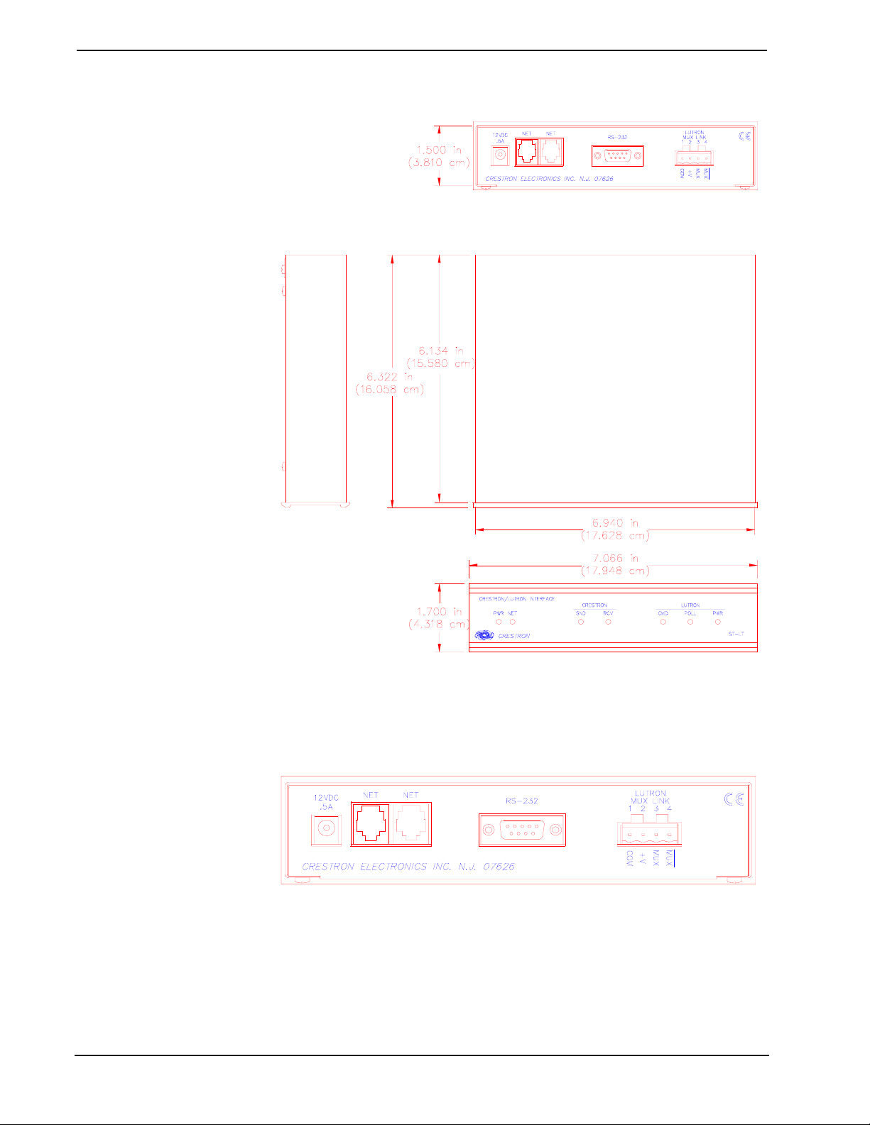
Physical Description
The ST-LT is housed in a black enclosure with silk-screened labels on the front and
rear panels. On the front of the unit there are seven LEDs for indicating the unit’s
current status. All connections are made on the back of the unit. Refer to the physical
views shown after this paragraph. There are four rubber feet on the base of the unit
for stability and to prevent slippage.
Operations Guide - Doc. 5694 Lutron Interface • 1
Page 6
CRESTRON
ST-LT Physical Views
ST-LT Ports
A number of ports are provided on the back of the ST-LT. Each has a silk-screened
label. Refer to illustration and descriptions below.
ST-LT Ports
12 VDC .5 A
This DC power socket connector is used to supply external power via the supplied
500 mA power pack (1000 mA power pack for the STI-LT). If the ST-LT is part of
the CRESNET II System, use of the supplied power pack is optional.
2 • Lutron Interface Operations Guide - Doc. 5694
Page 7
CRESTRON
NET
These two 6-pin, 6-position RJ11 modular jacks are used to connect the ST-LT
module to either the SmarTouch STS or CRESNET II remote control system. When
the module is part of the CRESNET II system, power is provided via the NET
connection; the supplied power pack need not be attached. Two NET ports are
available so that network units can be daisy-chained together. Review the latest
revision of the Network Modular Cable Requirements (Doc. 5682).
NOTE: Most 4-conductor phone cables are wired in a crisscross fashion and are not
compatible with CRESTRON equipment.
If the power pack is attached when the ST-LT is part of the CRESNET II system,
power is drawn from the power pack. The module does not load the network power,
but the network power remains chained for additional network devices that are
connected.
RS-232
This 9-pin (DB9) connector is a Lutron compatible RS-232 interface for connections
to a PC running Lutron configuration and control software. This connector is
equivalent to Lutron’s GRX-AV-RS232.
ST-LT Pinout (RS-232)
PIN DESCRIPTION
1
2
3
4
5
6
7
8
9
n/c
TXD
RXD
n/c
GND
n/c
CTS
RTS
n/c
A standard DB9 male to DB9 female straight-through cable may be used to connect
the RS-232 port of the ST-LT to a PC. This port is activated through the program
running on the control system. Refer to “Programming” on page 10 for more details.
LUTRON MUX LINK
This 4-pin connector connects to the Lutron Mux Link Network. The Lutron’s
network line (refer to the following table) is not compatible with the CRESTRON
network line; do not connect to each other.
Description of Lutron Network Lines
LUTRON DESCRIPTION
MUX*
MUX
+V
COM
DATA- Line
DATA+ Line
Voltage Line
Ground
Operations Guide - Doc. 5694 Lutron Interface • 3
Page 8
CRESTRON
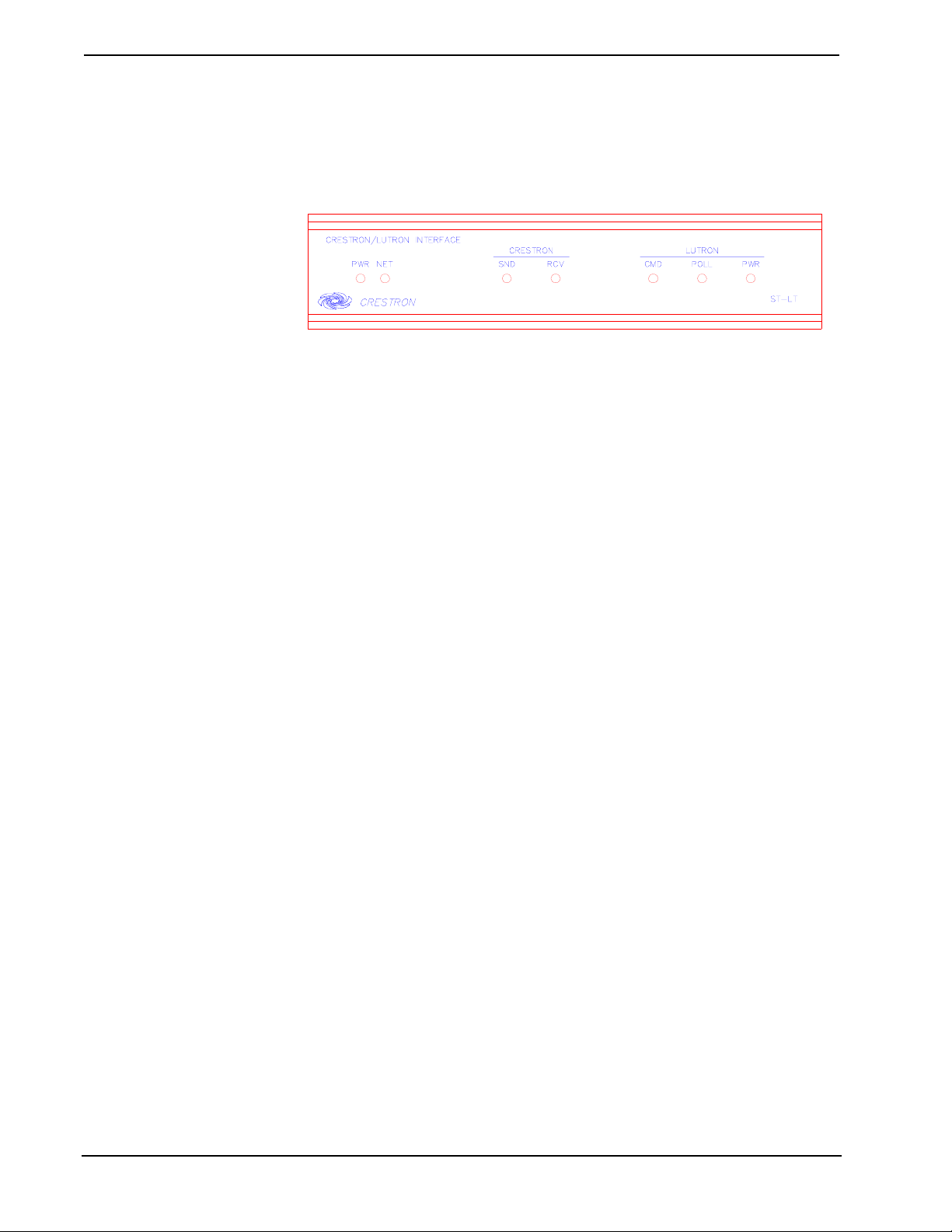
ST-LT Indicators
There are seven LED indicators located on the front panel of the ST-LT. Refer to
illustration and descriptions below.
ST-LT Indicators
PWR (Power)
This LED illuminates when 12 volts (from power packs) or 24 volts DC (from
network) is supplied to the ST-LT.
NET
This LED remains illuminated when communication between either the SmarTouch
STS or CRESNET II remote control system and the ST-LT is established.
Illumination indicates that the SIMPL program currently loaded has a network
device defined at the same ID as the ST-LT.
CRESTRON SND
This LED flashes when the ST-LT sends a command to the Lutron Mux Link
Network.
CRESTRON RCV
This LED flashes when the ST-LT receives a command from the Lutron Mux Link
Network.
LUTRON CMD
This LED illuminates when the Lutron Mux Link Network receives a command
from the CRESNET II System via the ST-LT. Once the command is completed, the
LED extinguishes.
LUTRON POLL
This LED illuminates when Lutron Mux Link polling occurs.
LUTRON PWR
This LED illuminates when voltage is supplied from the Lutron Mux Link Network.
4 • Lutron Interface Operations Guide - Doc. 5694
Page 9
CRESTRON
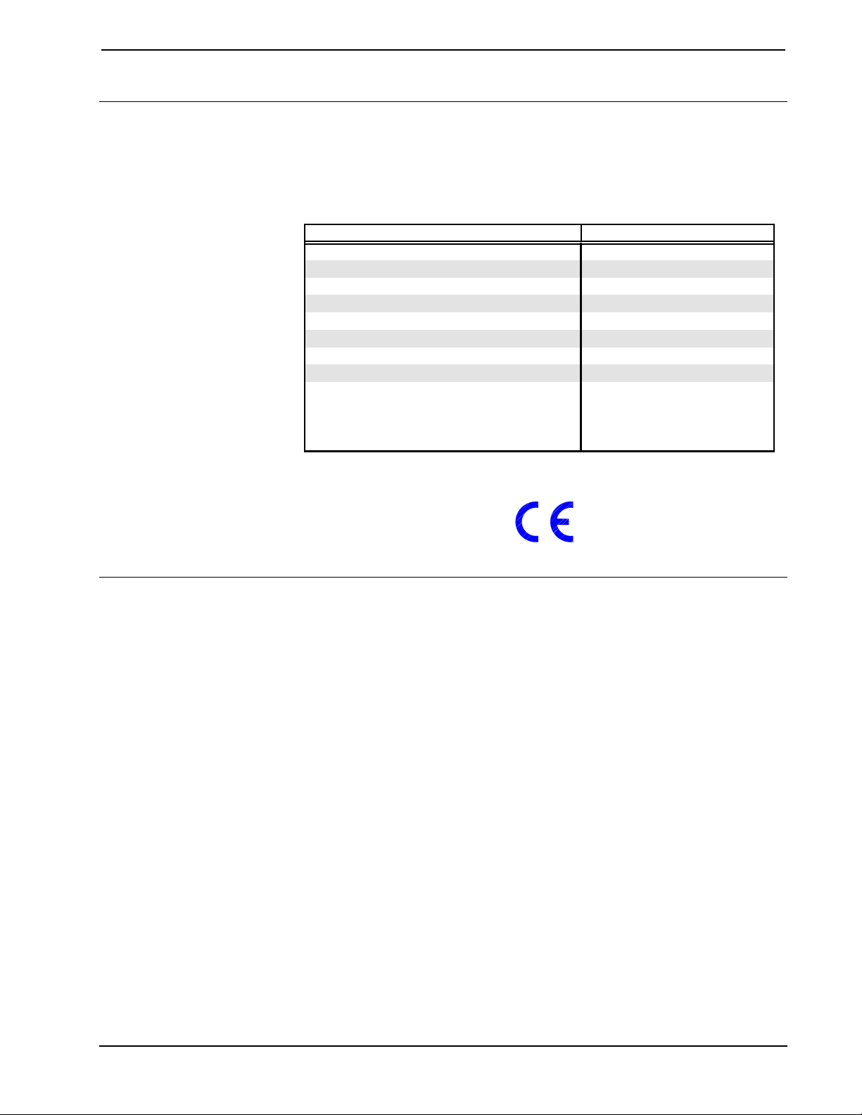
Leading Specifications
The table below provides a summary of leading specifications for the ST-LT
module. Dimensions and weight are approximations rounded to the nearest
thousandth unit.
Leading Specifications of the ST-LT
SPECIFICATION DETAILS
Power Requirements
Power Factor
CRESNET II Workshop
SIMPL Compiler
CRESNET II Operating System
SmarTouch Operating System
STS VisionTools
STS Database
Dimensions & Weight
TM
for Windows (STS/VTW)
12 or 24 VDC
2.5 Watts
Version 5.24 or later
3.18.04 or later
3.17.31 or later
Any
Version 10.7 or later
Version 10.7.100.02 or later
Height: 1.700 in (4.318 cm)
Width: 7.066 in (17.948 cm)
Depth: 6.322 in (16.058 cm)
Weight: 2.100 lb (0.953 kg)
Setup
As of the date of manufacture, the unit has been tested and found to comply with
specifications for CE marking.
Identity Code
Every equipment and user interface within the CRESNET II requires a unique
identity code (NET ID). These codes are recognized by a two-digit hexadecimal
number from 03 to FE. The NET ID of each unit must match an ID CODE specified
in the “NET.ID” statement of the CRESNET II SIMPL-I program in order for the
device to be addressed properly. The NET ID of each ST-LT has been factory set to
1C, but may be changed from the PC via STS/VTW software or the CRESNET II
Workshop.
Change NET ID via STS/VTW Software
Attach the ST-LT to SmarTouch STS or CRESNET II system (verify that the
STS/VTW software is running) and complete the following steps to change the NET
ID.
1. Disconnect all network devices from the CRESNET II network or
modular devices from the STS system, except for the one ST-LT that
needs to have its NET ID code changed.
2. Select ViewPort from the Tools pull-down menu to open the “Crestron
Performance Viewport” dialog box.
3. Select Set Network ID from the Options pull-down menu. The software
checks the baud rate and then opens the “Set Network ID” dialog box.
Operations Guide - Doc. 5694 Lutron Interface • 5
Page 10
CRESTRON
4. Notice the list of current network devices in the dialog box. Highlight
the ST-LT.
5. The factory set NET ID of the ST-LT (1C) appears in the dialog box.
Use the scroll arrow to assign the new NET ID.
6. When the newly assigned NET ID appears, select the Set ID button to
initiate the change.
7. The software responds with a successful message to confirm the new
NET ID.
8. To verify this procedure, select Report Network Devices from the
Options pull-down menu. Confirm that the ST-LT has the new NET ID
code.
9. Reconnect other network or modular devices that were disconnected in
step 1.
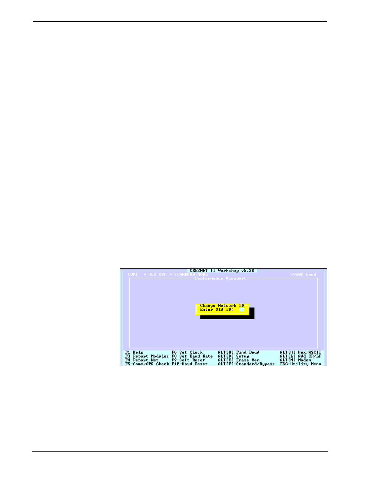
Change NET ID via CRESNET II Workshop (Workshop v5.20 or later and OPS version 3.16.11 or higher required)
Attach ST-LT to CRESNET II system (verify that the workshop is open and
running) and complete the following steps to change the NET ID.
1. Disconnect all network devices from the CRESNET II network or
modular devices from the STS system, except for the one ST-LT that
needs to have its NET ID code changed.
2. Highlight performance Viewport from the UTILITIES MENU of the
CRESNET II Workshop.
3. Depress the key combination ALT-I. The Workshop responds with the
screen shown below and requests the old NET ID code for the ST-LT
Changing the NET ID - ST-LT Workshop Screens (1 of 3)
4. Enter the old NET ID code (in two-digit hexadecimal format) and
depress ENTER. The Workshop responds with the screen shown after
this step and requests a new NET ID code for the ST-LT.
6 • Lutron Interface Operations Guide - Doc. 5694
Page 11

CRESTRON
Changing the NET ID - ST-LT Workshop Screens (2 of 3)
5. Enter a new NET ID code (in two-digit hexadecimal format) and
depress ENTER. The Workshop responds with the screen shown below
that displays a message stating the “New ID” command has been sent.
Changing the NET ID - ST-LT Workshop Screens (3 of 3)
6. To verify this procedure, depress F4 to perform a network poll.
Confirm that the ST-LT has the new NET ID code.
7. Reconnect other network or modular devices that were disconnected in
step 1.
Dip Switch Settings for GRAFIK Eye Use
An eight-position dip switch is mounted to the ST-LT PC board. The switch
positions (switches 6 and 7 ON) are factory set for typical use of the ST-LT within a
CRESNET II System or SmarTouch STS. However, in certain GRAFIK Eye
systems, the switch positions may need to be altered.
If it is determined that the switch settings must be changed, power down the ST-LT
and complete the following steps.
1. Turn the unit over and place it top-side down on a soft, clean surface.
2. Loosen and remove four screws and washers that secure the top cover
to the ST-LT.
3. Lift, turn the unit over, and place the unit down on its four rubber feet.
Operations Guide - Doc. 5694 Lutron Interface • 7
Page 12

CRESTRON
4. Slide the top cover toward the back panel while holding the ST-LT in
place until the cover is free.
5. Locate the dip switch and notice the orientation (#1 - #8); refer to
illustration below.
Location of Dip Switch on ST-LT PC Board
ST-LT PORTS
DETAIL OF
8-POSITION
DIP SWITCH
O
786
5
3
4
N
2
1
SW2
ST-LT LEDS
6. Refer to the table below for the dip switch settings for your particular
application. Move the appropriate switch to the ON position to enable
the desired function described in the table.
Dip Switch Functional Description for GRAFIK Eye Use
SWITCH FUNCTION DESCRIPTION
1 Zone Lock Retain
2 Scene Lock Retain
3 Sequence Retain
4 Sequence Type
5 Not Used
6 Raw Feedback
7 Scene Status
8 Not Used
Zone locked units will remain in zone lock after a
power outage.
Scene locked units will remain in scene lock after a
power outage.
Sequencing units will again sequence after a power
outage.
ON: Sequence scenes 5 - 16
OFF: Sequence scenes 1 - 4
Unit will inform RS232 link when any button is
pushed on a GRAFIK Eye main unit or accessory.
Unit will inform RS232 link when a new scene is
selected.
7. Replace the cover by sliding it over the unit and secure with four
screws and washers.
8. Apply power to the ST-LT.
8 • Lutron Interface Operations Guide - Doc. 5694
Page 13

CRESTRON
Preparation for Use
Refer to the two hookup diagrams below. The first diagram illustrates the
connections to SmarTouch STS. The second diagram shows connections to the
CRESNET II system. Other than making the power connection last, complete the
connections in any order, regardless of whether the ST-LT is part of SmarTouch
STS or the CRESNET II system.
NOTE: Refer to the latest revision of the CRESTRON Network Modular Cable
Requirements (Doc. 5682) when making connections to the port labeled NET.
SmarTouch STS Hookup Connections for ST-LT
USE 2 FOOT SUPPLIED CABLE (CA15717)
OR EQUIVALENT (EXTENDED LENGTH) TO
CONNECT ST-LT TO SMARTOUCH STS.
NOTE:
SMARTOUCH STS
(ST-CP)
POWER PACK
(500 mA)
(1000 mA
for STI-LT)
PC
DAISY CHAIN
TO ADDITIONAL
NETWORK DEVICES
CRESNET II System Hookup Connections for ST-LT
USE ST-CNB (SOLD SEPARATELY) TO
CONNECT ST-LT TO CRESNET II SYSTEM.
NOTE:
CRESNET II SYSTEM
(CNRACK OR CNRACK-D
OR CNMS)
PC
LUTRON
MUX LINK
NETWORK
LUTRON
MUX LINK
NETWORK
OPTIONAL
POWER PACK
(500 mA)
(1000 mA
for STI-LT)
DAISY CHAIN
TO ADDITIONAL
NETWORK DEVICES
Operations Guide - Doc. 5694 Lutron Interface • 9
Page 14

CRESTRON
Programming
Using STS/VTW Software
NOTE: The following description assumes that the reader has some knowledge of
STS/VTW software. If not, please refer to the SmarTouch Tutorial that is available
from the STS/VTW Help menu.
Use STS/VTW software (version 10.7 or higher and STS database version
10.7.100.02 or later) to include the ST-LT in lieu of a Lutron GRAFIK Eye device
into a SmarTouch system. Once included, a command sequence or macro must be
enabled via software. The macro prompts which MAIN-UNIT is controlled and
dictates which actions are to be followed. The procedural steps that follow this
paragraph provide the general course necessary to include the ST-LT into a
SmarTouch system and build and assign a macro.
1. Select Open and Smartouch System from the File menu to open a
specific SmarTouch system. The software displays the “SmarTouch
Pro Editor” dialog box (formally known as “SmarTouch System
Manager”).
Alternatively, the ST-LT can
be selected by choosing
Lighting, Lutron, and
GRAPHIK Eye via ST-LT in
the appropriate fields.
2. Double click on the next available open device (DEVICE #) in the
Devices section of the dialog box. The software displays the “Device
Selection and Configuration” dialog box.
3. Define the device by selecting the Crestron Database, Lighting (as the
type), Crestron (as the manufacturer), and ST-LT (as the Model). For
this sample, replace DEVICE # with ST-LT in the [Name:] field. By
default, a Net ID of 1C is assigned. The dialog box should appear as
shown below; click OK.
Device Selection and Configuration Dialog Box
4. Once the ST-LT has been added to the SmarTouch system,
functionality must be assigned to buttons residing on a lighting page.
10 • Lutron Interface Operations Guide - Doc. 5694
Page 15

CRESTRON
p
Select Open and Project from the File menu to open the touchpanel
project file. For this sample, the project has been named
LUTRON.PRJ.
This lighting page, shown
below, was taken from the
VTW Template subdirectory,
TST1500C.PRJ, page name
LIGHT-LUTRON-GEYERS232.
HINT: An alternate method
would be to address the
MAIN-UNIT # when the
button that opens the lighting
age is depressed. Buttons on
the lighting page can then be
assigned individual (SCENE
or ZONE) commands.
5. Open or create a lighting page with associated buttons. The STS
Wizard uses template projects, many of which offer typical lighting
pages. One such page is shown below. To use a page from the
template, copy it to the touchpanel project and customize as needed.
Refer to Copy and Paste from the STS/VTW Help menu for details.
Lighting Page Sample
6. While the lighting page is open, a macro must be defined to identify
the MAIN-UNIT # and assign specific SCENE or ZONE commands.
The MAIN-UNIT # assignment only needs to be sent once . If
controlling multiple MAIN-UNITS, it can also be included and sent
each time there is a SCENE or ZONE change. Select Create Macro
from the Control menu to open the “Macro Edit” dialog box.
7. Replace MACRO # in the [Name:] field with a relevant name such as
Zone1-Up. The dialog box should appear as shown below.
Macro Edit Dialog Box
Operations Guide - Doc. 5694 Lutron Interface • 11
Page 16

CRESTRON
The macro in this sample
shall address MAIN-UNIT-2
and select ZONE-1-UP.
8. A macro is created by adding the appropriate commands and delays as
required. Click the Insert Command button to open the “Device
Functions” dialog box.
8. Highlight the ST-LT in the Device area to display the associated
functions in the right-hand column.
9. Select MAIN-UNIT-2 as the desired function. The dialog box should
appear as shown below; click OK.
Device Functions Dialog Box
11. The software returns to the “Macro Edit” dialog box. Notice that the
first step of the macro addresses MAIN-UNIT-2. Click on Insert
Command, ZONE-1-UP from the Function area, and OK. Once the
macro is complete, select OK to close the “Macro Edit” dialog box.
12. Next, the function must be assigned to a specific button on the lighting
page. With the lighting page open, right-mouse click on the ZONE 1
UP button and select Function from the pop-up.
13. The software displays the “Function” dialog box for that given button.
Click on the [Macro:] field and select ZONE1-UP. The dialog box
should appear as shown below; click OK.
Function Dialog Box
14. Additional macros should be created and assigned for each button on
the lighting page that provides a function. Therefore, repeat steps 6
through 13 for the appropriate buttons.
12 • Lutron Interface Operations Guide - Doc. 5694
Page 17

CRESTRON
K
SIMPL
SIMPL is CRESTRON’s programming language designed for easy implementation
of the control system requirements. The best representation of SIMPL programming
is the block diagram. A basic ST-LT SIMPL program is shown and described below.
ST-LT SIMPL Program
CT-1500
NET.ID:03
1
2
3
4
UNIT1-SCENE2
UNIT7+8-SCENE16
UNIT3-ZONE1-
MV
0
TRIG
[TRIG*]
0.1s
UNIT3-ZONE1+
MV
TRIG
0
[TRIG*]
0.1s
STOP-DOWN-ALL
OUT :E
S-#
OUT
S-#
STOP-UP-ALL
ST-COM
:A21
:AG78
:D31
:B31
:C
NET.ID:04
BAUD=GRAFI
The sample ST-LT SIMPL program allows two scenes for the Grafik Eye; scene 2
on Main Unit 1 and scene 16 on Main Units 7 and 8. It also allows zone 3 to be
ramped up and down. The MV symbols are used to detect the release of the UP and
DOWN buttons which results in the transmission of the appropriate zone up/down
stop commands.
Workshop
The CRESNET II Workshop is designed to simplify the various operations needed
to program and run a CRESNET II control system. The series of screen displays
shown below are accessible from the “Define Network” option of the SIMPL-I
Menu in the CRESNET II Workshop. These screens are shown to clarify the means
of assigning signal names for the SIMPL program in the previous illustration.
ST-LT Workshop Screens (1 of 4)
The ST-LT definition supports a subset of the ST-COM definition; use A_IN,
A_OUT for serial string transmission as well as the regular “in” and “out” directions
for hard-coding serial data.
Operations Guide - Doc. 5694 Lutron Interface • 13
Page 18

CRESTRON
ST-LT Workshop Screens (2 of 4)
ST-LT Workshop Screens (3 of 4)
ST-LT Workshop Screens (4 of 4)
The ST-LT is defined as an “ST-COM, Port A”. Enter “GRAFIK” into the baud rate
field to allow the ST-LT to communicate with the Grafik Eye unit. The fields for
parity, data bits, and stop bits are not used and may be set to any value.
If Port B is defined to be 9600 N81, a RS-232 link to the Grafik Eye unit through the
RS-232 port on the back of the ST-LT is permitted. The RS-232 port is bidirectional;
data can be transmitted and received to/from the Grafik Eye. Typically, this port is
used for debugging only. A standard DB9 male/DB9 female straight-through cable is
used to go from this port to a PC.
14 • Lutron Interface Operations Guide - Doc. 5694
Page 19

CRESTRON
The data field contains the command protocol for the Grafik Eye system. A
description of commands, their operation, and examples are provided in the table
below.
Commands for GRX-AV-RS232 and GRX-AV-RS232/ATC
OPERATION CMD PARAMETERS EXAMPLES
Select Scene
Scene Lock
Request Scene Status
Sequence
Zone Lock
Zone Lower
Zone Lower Stop
Zone Raise
Zone Raise Stop
Set Time*
Report Time*
Select Schedule*
Report Schedule* RS
Report Sunrise/Sunset* RA
Super Sequence Start* QS
Super Sequence Pause* QP
Super Sequence Resume*
[scene][main units]
A
[+]or[-][main units]
SL
G NONE :G report scene status of all units on link
[+]or[-][main units]
SQ
[+]or[-][main units]
ZL
[main unit][zones]
D
E NONE :E stop ramping down all zones on all units
[main unit][zones]
B
C NONE :C stop ramping up all zones on all units
[hr][min][mth][day]
ST
con. [yr][dayofweek]
RT NONE :RT report current time and date of control
SS
QC NONE :QC resume super sequence at next event
[schedule]
NONE
NONE
NONE
NONE
:A21 select scene 2 on unit 1
:AG78 select scene 16 on units 7 & 8
:SL release all units from scene lock
:SL-6 release only unit 6 from lock
:SL+45 additionall lockout units 4 & 5
:SQ release all unitsfrom sequence mode
:SQ-3 release only unit 3 from sequencing
:SQ+68 add units 6 & 8 to sequencing
:ZL release all units from zone lock
:ZL-1 release only unit 1 from lock
:ZL+36 additionally lockout units 3 & 6
:D5 stop ramping down all zones on unit 5
:D3124 ramp down zones 1,2 & 4 on unit 3
:B5 stop ramping up all zones on unit 5
:B3124 ramp up zones 1,2 & 4 on unit 3
:ST 1 35 10 26 95 5 set time and date to 1:35am,
Thursday, October 26, 1995
response ~:rt
:SS1 start weekday schedule
:RS which schedule is currently running
response ~:rs
:RA report sunrise time and sunset time
response ~:ra
:QS start super sequence at first event
:QP stop super sequence at current event
hr min month day yr dayofweek
schedule
rise_hr rise_min set_hr set_min
NOTE: Command operations denoted with an asterisk (*) are for GRX-AV-RS2323/ATC only.
For a more comprehensive description of commands refer to “Appendix: GRAFIK Eye
Commands” on page 18.
Operations Guide - Doc. 5694 Lutron Interface • 15
Page 20

CRESTRON
Problem Solving
Troubleshooting
The table below provides corrective action for possible trouble situations. If further
assistance is required, please contact a CRESTRON technical support representative.
ST-LT Troubleshooting
TROUBLE
PWR LED
does not
illuminate.
NET LED
does not
illuminate. Loose network
LUTRON
PWR LED
does not
illuminate.
POSSIBLE
CAUSE(S)
ST-LT is not receiving
power.
Improper NET ID. Verify that ST-LT NET ID matches NET ID
connection.
Lutron Mux Link
Network is not
receiving power.
Confirm that power pack securely plugged
into outlet and that the connector is properly
attached to the ST-LT.
Verify that proper cables are securely
attached to ST-LT NET connectors (for
CRESNET II system only).
software program. Refer to "Identity Code".
Verify that cables attached to ST-LT NET
connectors are proper and secure.
Verify that the Lutron Mux Link Network
power supply is securely attached to the
network.
CORRECTIVE ACTION
Further Inquiries
If after reviewing this Operations Guide for the ST-LT, you can not locate specific
information, please take advantage of CRESTRON's award winning technical
support team in your area. Dial one of the following numbers.
• In the US and Canada, call Crestron’s corporate headquarters at
1-888-CRESTRON [1-888-273-7876] or 1-201-767-3400.
• In Europe, call Crestron International at +32-15-50-99-50.
• In Asia, call Crestron Asia at +852-2341-2016.
• In Latin America, call Crestron Latin America at +5255-5093-2160.
• In Australia, call Crestron Pacific at +613-9480-2999.
For local support from exclusive Crestron factory-trained personnel in New Zealand
call Amber Technologies at +649-410-8382.
Syntax
The following syntax codes for the ST-LT are provided for compatibility purposes
only.
NET.ID <03 to FE>: ST-COM
COMSPECA = GRAFIK \GRAFIK Eye Port
TXA$ = <signal name> \Serial signal defining data stream out to
\GRAFIK Eye
RXA$ = <signal name> \Serial signal in from GRAFIK Eye
COMSPECB = 9600,N,8,1 \GRAFIK Eye Port
16 • Lutron Interface Operations Guide - Doc. 5694
Page 21

CRESTRON
Return and Warranty Policies
Merchandise Returns / Repair Service
1. No merchandise may be returned for credit, exchange, or service without prior authorization
from CRESTRON. To obtain warranty service for CRESTRON products, contact the factory
and request an RMA (Return Merchandise Authorization) number. Enclose a note specifying
the nature of the problem, name and phone number of contact person, RMA number, and
return address.
2. Products may be returned for credit, exchange, or service with a CRESTRON Return
Merchandise Authorization (RMA) number. Authorized returns must be shipped freight
prepaid to CRESTRON, Cresskill, N.J., or its authorized subsidiaries, with RMA number
clearly marked on the outside of all cartons. Shipments arriving freight collect or without an
RMA number shall be subject to refusal. CRESTRON reserves the right in its sole and
absolute discretion to charge a 15% restocking fee, plus shipping costs, on any products
returned with an RMA.
3. Return freight charges following repair of items under warranty shall be paid by
CRESTRON, shipping by standard ground carrier. In the event repairs are found to be nonwarranty, return freight costs shall be paid by the purchaser.
CRESTRON Limited Warranty
CRESTRON ELECTRONICS, Inc. warrants its products to be free from manufacturing defects in
materials and workmanship under normal use for a period of three (3) years from the date of
purchase from CRESTRON, with the following exceptions: disk drives and any other moving or
rotating mechanical parts, pan/tilt heads and power supplies are covered for a period of one (1)
year; touchscreen display and overlay components are covered for 90 days; batteries and
incandescent lamps are not covered.
This warranty extends to products purchased directly from CRESTRON or an authorized
CRESTRON dealer. Purchasers should inquire of the dealer regarding the nature and extent of the
dealer's warranty, if any.
CRESTRON shall not be liable to honor the terms of this warranty if the product has been used in
any application other than that for which it was intended, or if it has been subjected to misuse,
accidental damage, modification, or improper installation procedures. Furthermore, this warranty
does not cover any product that has had the serial number altered, defaced, or removed.
This warranty shall be the sole and exclusive remedy to the original purchaser. In no event shall
CRESTRON be liable for incidental or consequential damages of any kind (property or economic
damages inclusive) arising from the sale or use of this equipment. CRESTRON is not liable for
any claim made by a third party or made by the purchaser for a third party.
CRESTRON shall, at its option, repair or replace any product found defective, without charge for
parts or labor. Repaired or replaced equipment and parts supplied under this warranty shall be
covered only by the unexpired portion of the warranty.
Except as expressly set forth in this warranty, CRESTRON makes no other warranties, expressed
or implied, nor authorizes any other party to offer any other party to offer any warranty, including
any implied warranties of merchantability or fitness for a particular purpose. Any implied
warranties that may be imposed by law are limited to the terms of this limited warranty. This
warranty statement supercedes all previous warranties.
Trademark Information
All brand names, product names, and trademarks are the sole property of their respective owners. Windows is a registered
trademark of Microsoft Corporation. Windows95/98/Me/XP and WindowsNT/2000 are trademarks of Microsoft
Corporation
Operations Guide - Doc. 5694 Lutron Interface • 17
Page 22

CRESTRON
r
r
Appendix: GRAFIK Eye Commands
NOTE: This entire appendix is a reprint of Lutron’s technical reference material.
Format for Commands
The RS-232 interface is commanded by ASCII strings in the following format.
: A 1 2 3 ... <CR>
Clea
Input
uffe
Notice that capital letters must be used for commands and there are no spaces
between characters. To execute more than one command, enter a space instead of the
carriage return and enter the next command. Any number of commands can be
entered at one time, as long as the input buffer is less than or equal to 60 characters.
The commands are executed in the order they are entered. When commands have
been received by the RS-232 interface, the number of commands executed is
reported by the unit to the RS-232 link. The format for this is a statement in the
following form.
<CR><LF>~3 OK<CR><LF>
If unrecognizable data is received, an error statement in the following form is
reported.
<CR><LF>~ERROR # 6 0 OK<CR><LF>
The first number indicates the type of error and the second number indicates the
number of commands executed before the error. When referring to GRAFIK Eye
Main Units as command parameters, GRAFIK Eye 1 refers to the GRAFIK Eye
Main Unit addressed as A1; GRAFIK Eye 2 refers to the GRAFIK Eye Main Unit
addressed as A2, and so on. Up to eight GRAFIK Eye Main Units can be on the
MUX link.
Command
Command
Parameters
Carriage
Return
GRX-AV-RS232 Command List
The following is a list of commands which can be used with both the GRX-AVRS232 and the GRX-AV-RS232/ATC Interface Controls.
(A) Select Scene
This command selects desired scenes on the specified GRAFIK Eye Main Unit(s).
The first parameter is the scene and the second is the GRAFIK Eye Main Unit(s)
which selects that scene. If an invalid GRAFIK Eye number is encountered, the
command only affects the GRAFIK Eye Main Units listed before the invalid entry.
For scene 10 enter an “A”; for scene 11, enter a “B”, and so on up to scene 16. Scene
numbers outside the range of 0-G return an error statement.
18 • Lutron Interface Operations Guide - Doc. 5694
Page 23

CRESTRON
Examples:
:A21<CR>
:AG45 A78<CR>
:A0123 A145 A38<CR>
Select scene 2 on GRAFIK Eye Main Unit 1.
Select scene 16 on GRAFIK Eye Main Units 4 and 5;
select scene 7 on GRAFIK Eye Main Unit 8.
Turn off GRAFIK Eye Main Units 1, 2 and 3; select
scene 1 on GRAFIK Eye Main Units 4 and 5; select
scene 3 on GRAFIK Eye Main Unit 8.
(SL) Scene Lock
When a GRAFIK Eye Main Unit is selected by this command, it is locked in the
current scene and does not allow lighting changes. To scene lock GRAFIK Eye Main
Units, enter a “+” for the first parameter; to release GRAFIK Eye Main Units from
scene lock, enter a “-”. For the second parameter, enter the GRAFIK Eye Main Units
that need to be selected or deselected. If the “+” or “-” is omitted, all GRAFIK Eye
Main Units are released from scene lock, except for those listed. Notice that all
GRAFIK Eye Main Units can be released manually from scene lock by switching
dip switch 2 from the ON to the OFF position. Also note that if another GRAFIK
Eye accessory is holding a Main Unit in scene lock, neither this command nor dip
switch 2 releases it.
Examples:
:SL<CR>
:SL2<CR>
:SL-3<CR>
:SL+68<CR>
:SL-5678 SL+1 <CR> Release GRAFIK Eye Main Units 5, 6, 7, and 8 from
Release all GRAFIK Eye Main Units from
lock
.
Scene lock
others.
Release GRAFIK Eye Main Unit 3 from
while not affecting the status of other GRAFIK Eye
Main Units.
Scene lock
addition to the units already selected).
scene lock
1, but do not change the status of 2, 3, and 4.
GRAFIK Eye Main Unit 2 and release all
GRAFIK Eye Main Units 6 and 8 (in
scene lock
and
GRAFIK Eye Main Unit
scene
scene lock
,
(G) Request Scene Status
This command returns the current scene of all eight GRAFIK Eye Main Units on the
MUX link.
Example:
:G<CR>
The response is “~:ss” followed by a string of eight ASCII characters, one for each
GRAFIK Eye Main Unit. Each character represents the current status of each
GRAFIK Eye Main Unit. The scene is indicated by its number. Scene 10 is indicated
by an ‘A’; scene 11 is indicated by a ‘B’, and so on up to scene 16. A ‘0’ is returned
if the GRAFIK Eye Main Unit is OFF and an ‘M’ is returned if the GRAFIK Eye
Main Unit is missing or not responding. An ‘R’ is returned if a master raise is being
sent and an ‘L’ is returned if a unit is sending a master lower.
Request scene status
.
Operations Guide - Doc. 5694 Lutron Interface • 19
Page 24

CRESTRON
g
Example of Response:
<CR><LF>~:ss2L0MAR95 1 OK<CR><LF>
Main Unit A1 is in scene 2
Main Unit A2 is sending a master
Main Unit A3 is OFF
Main Unit A4 is missin
Main Unit A5 is in scene 10
Main Unit A6 is sending a master
Main Unit A7 is in scene 9
Main Unit A8 is in scene 5
lower
raise
(SQ) Sequence
This command determines which GRAFIK Eye Main Units are sequenced (changed
from scene to scene with fade times set by GRAFIK Eye Main Units). Two
sequences can be selected, depending on the setting of dip switch 4. If dip switch 4
is OFF, the GRAFIK Eye Main Units selected by this command sequence through
scenes 1-4. If it is ON, they sequence through scenes 5-16. The command
parameters are the same as for scene lock. Notice that all GRAFIK Eye Main Units
can be taken manually out of sequence mode by switching dip switch 3 from the ON
to the OFF position. Also note that if another GRAFIK Eye accessory is sequencing
a Main Unit, neither this command nor dip switch 3 releases it.
Examples:
:SQ<CR>
:SQ2<CR>
:SQ+68<CR>
:SQ-3<CR>
:SQ-5678 SQ+1<CR>
Take all GRAFIK Eye Main Units out of sequence
mode .
Sequence GRAFIK Eye Main Unit 2 and take all
other GRAFIK Eye Main Units out of sequence
mode.
Sequence GRAFIK Eye Main Units 6 and 8 (in
addition to the units already selected).
Take GRAFIK Eye Main Unit 3 out of sequence
mode, while not affecting the status of other GRAFIK
Eye Main Units.
Take GRAFIK Eye Main Units 5, 6, 7, and 8 out of
sequence mode and sequence GRAFIK Eye Main
Unit 1, but do not change the status of 2, 3, and 4.
(ZL) Zone Lock
When a GRAFIK Eye Main Unit is selected by this command, the intensity of zone
levels preset in its memory cannot be altered. The level of the zone can be changed,
but preset memory is write-protected. The command parameters are the same as for
scene lock and sequence. Notice that all GRAFIK Eye Main Units can be released
manually from zone lock by switching dip switch 1 from the ON to the OFF
position. Also note that if another GRAFIK Eye accessory is holding a Main Unit in
zone lock, neither this command nor dip switch 1 releases it.
Examples:
:ZL<CR>
:ZL2<CR>
:ZL+68<CR>
:ZL-3<CR>
20 • Lutron Interface Operations Guide - Doc. 5694
Release all GRAFIK Eye Main Units from zone lock .
Zone lock GRAFIK Eye Main Unit 2 and release all
other GRAFIK Eye Main Units from zone lock .
Zone lock GRAFIK Eye Main Units 6 and 8 (in
addition to the units already selected).
Release GRAFIK Eye Main Unit 3 from zone lock ,
while not affecting the status of other GRAFIK Eye
Main Units.
Page 25

CRESTRON
(D) Zone Lower
This command causes the zones of the selected GRAFIK Eye Main Units to
gradually decrease in intensity. The first parameter is the GRAFIK Eye Main Unit
and the second is the zone(s) affected. Any zone numbers not listed are unaffected.
If the command is given for a GRAFIK Eye Main Unit and no zones are listed,
zones that are currently ramping down on that Main Unit stop. Invalid GRAFIK Eye
numbers return an error statement.
Examples:
:D11357<CR>
:D781 D32<CR>
:D5 D52 D18<CR>
:D1 D2 D3<CR>
Ramp down zones 1, 3, 5, and 7 of GRAFIK Eye
Main Unit 1.
Ramp down zones 8 and 1 of GRAFIK Eye Main Unit
7 and zone 2 of GRAFIK Eye Main Unit 3.
Stop all zones on GRAFIK Eye Main Unit 5 that are
currently ramping down; ramp down zone 2 of
GRAFIK Eye Main Unit 5 and zone 8 of GRAFIK Eye
Main Unit 1.
Stop ramping down all zones on GRAFIK Eye Main
Units 1, 2, and 3.
(E) Zone Lower Stop
This command cancels all zone lower commands. It is used as a short cut for sending
the D command with no zones and all GRAFIK Eye Main Units.
Example:
:E<CR>
Stop all zones on all GRAFIK Eye Main Units
that are ramping down.
(B) Zone Raise
This command causes the zone(s) listed on the given GRAFIK Eye Main Unit to
gradually increase in intensity and has the same parameters as zone lower. Zone
numbers not listed are unaffected. If the command is given for a GRAFIK Eye Main
Unit and no zones are listed, any zones on the GRAFIK Eye Main Unit that are
currently ramping up are stopped. Invalid GRAFIK Eye numbers return an error
statement.
Examples:
:B11357<CR>
:B781 B23<CR>
:B1 B2 B3<CR>
:B5 B52 B18<CR>
Ramp up zones 1, 3, 5, and 7 of GRAFIK Eye Main
Unit 1.
Ramp up zones 8 and 1 of GRAFIK Eye Main Unit 7
and zone 3 of GRAFIK Eye Main Unit 2.
Stop all zones on GRAFIK Eye Main Units 1, 2, and
3 that are currently ramping up.
Stop all zones on GRAFIK Eye Main Unit 5 that are
currently ramping up; ramp up zone 2 of GRAFIK
Eye Main Unit 5 and zone 8 of GRAFIK Eye Main
Unit 1.
Zone Raise Stop
This command cancels all zone raise commands. It is used as a short cut for sending
the B command listing no zones and all Main Units.
Operations Guide - Doc. 5694 Lutron Interface • 21
Page 26

CRESTRON
Examples:
:C<CR>
:C E<CR>
Stop all zones on all GRAFIK Eye Main Units that
are ramping up.
Stop all zones that are being raised or lowered.
GRX-AV-RS232/ATC Command List
The following set of commands can be used only with the GRX-AV-RS232/ATC.
(ST) Set Time
This command sets the internal timeclock to the given time and date. The seconds
are reset to 00 when the command is issued. Notice that the timeclock can be set
directly through Lutron’s GRAFIK Eye Timeclock software. There are six command
parameters, with a space between each.
Parameter 1 Hour 0-23 (24 hour format)
Parameter 2 Minute 0-59
Parameter 3 Month 1-12
Parameter 4 Date 1-31
Parameter 5 Year 0-99
Parameter 6 Day of week 1-7
Examples:
:ST 2 14 7 30 71 6<CR>
:ST 17 4 10 31 95 3<CR>
Set time to 2:14 AM on July 30, 1971; the day of
week is set to Friday.
Set time to 5:04 PM on October 31, 1995; the day of
week is set to Tuesday.
(RT) Report Time
This command reports the current time and date of the internal timeclock. If this
command is entered on a GRX-AV-RS232 unit, an error condition is issued.
Example:
:RT<CR>
Report time
.
The response is “:rt” and then a string of numbers indicating the time and date in the
same order that it would be entered using the set time command.
Example of Responses:
<CR><LF>~:rt 2 14 7 30 71 6 1 OK<CR><LF>
<CR><LF>~:rt 17 4 10 31 95 3 1 OK<CR><LF>
The time is 2:14 AM on July 30,
1971; the day of week is Friday.
The time is 5:04 PM on October
31, 1995; the day of week is
Tuesday.
(SS) Select Schedule
This command determines which schedule the GRX-AV-RS232/ATC is running.
The GRX-AV-RS232/ATC executes the next event that was to occur in the schedule
selected. The schedules themselves can only be altered through Lutron’s GRAFIK
Eye Timeclock software. The execution of a schedule can be temporarily suspended
by turning dip switch 8 to the OFF position. There is only one parameter for this
command, a number which selects the schedule.
22 • Lutron Interface Operations Guide - Doc. 5694
Page 27

CRESTRON
0 = no schedule active
1 = "weekday" schedule
2 = "weekend" schedule
3 = "special 1" schedule
4 = "special 2" schedule
Any other value causes no schedule to be run.
Examples:
:SS 4<CR>
:SS 0<CR>
Start special schedule 4.
Stop timeclock from executing events.
(RS) Report Schedule
This command tells the unit to report the schedule that it is currently running. If this
command is used on a GRX-AV-RS232 unit, an error condition is issued.
Example:
:RS<CR>
Report schedule
The response is “:rs” followed by a number indicating the schedule that is running.
0 = no schedule active
1 = "weekday" schedule
2 = "weekend" schedule
3 = "special 1" schedule
4 = "special 2" schedule
Example of Responses:
.
<CR><LF>~:rs 0 1 OK<CR><LF>
<CR><LF>~:rs 3 1 OK<CR><LF>
No schedule is running.
Special schedule 3 is running.
(RA) Report Sunrise/Sunset Times
This command tells the GRX-AV-RS232/ATC to report the time that the sun rises
and sets today, according to the unit’s internal astronomical timeclock. If this
command is used on a GRX-AV-RS232 unit, an error condition is issued.
Example:
:RA<CR>
Report sunrise/sunset times
.
The response is “:ra” followed by the sunrise time (hours then minutes) and the
sunset time (hours then minutes).
Example of Response:
<CR><LF>~:ra 5 34 17 21 1 OK<CR><LF>
The sunrise is at 5:34 AM; the
sunset is at 17:21 (5:21 PM)
(QS) Super Sequence Start
A super sequence is a command to the GRX-AV-RS232/ATC from a PC through
Lutron’s GRAFIK Eye Timeclock software (part number GRXTC-WIN). It provides
GRAFIK Eye Main Units with a user-selected set of scenes through which to
sequence. This command initiates the preprogrammed super sequence starting from
step 1. If a super sequence is not loaded into the unit, an error condition is issued. If
the super sequence is running when this command is issued, it jumps immediately to
step 1 and continues from that point.
Operations Guide - Doc. 5694 Lutron Interface • 23
Page 28

CRESTRON
Example:
super sequence
:QS<CR>
Start
.
(QP) Super Sequence Pause
This command stops the preprogrammed super sequence that is running at its current
step. If a super sequence is not running, the command does nothing. If a super
sequence has not been loaded using the GRAFIK Eye Timeclock software, an error
statement is reported. The sequence can be restarted from this point by a super
sequence resume command.
Example:
super sequence
:QP<CR>
Stop
at the current step.
(QC) Super Sequence Resume
This command restarts a stopped super sequence by immediately selecting the next
step. If a super sequence is not loaded, an error statement is reported.
Example:
:QC<CR>
Continue
super sequence
from the current step.
24 • Lutron Interface Operations Guide - Doc. 5694
Page 29

CRESTRON
This page intentionally left blank.
Operations Guide - Doc. 5694 Lutron Interface • 25
Page 30

CRESTRON
This page intentionally left blank.
26 • Lutron Interface Operations Guide - Doc. 5694
Page 31

CRESTRON
This page intentionally left blank.
Operations Guide - Doc. 5694 Lutron Interface • 27
Page 32

 Loading...