

Page 1

Crestron SIMPL™ Windows®
Symbol Guide
Page 2

This document was prepared and written by the Technical Documentation department at:
Crestron Electronics, Inc.
15 Volvo Drive
Rockleigh, NJ 07647
1-888-CRESTRON
All brand names, product names and trademarks are the property of their respective owners.
©2002 Crestron Electronics, Inc.
Page 3

Crestron SIMPL™ Windows® Software
Contents
Symbols 1
Introduction ...............................................................................................................................1
Device Symbols......................................................................................................................... 2
Cresnet Control Modules ................................................................................................... 2
Cresnet Audio Modules....................................................................................... 2
Cresnet Camera Controllers ..............................................................................11
Cresnet I/O & Other Modules ...........................................................................13
Cresnet Power Control Modules .......................................................................17
Cresnet Sensing Modules .................................................................................. 18
Cresnet Video Modules.....................................................................................19
Cresnet Remote Processing...............................................................................23
Ethernet Control Modules ................................................................................................ 29
Ethernet Modules (Crestron) ............................................................................. 29
Ethernet Modules (Generic) .............................................................................. 36
Ethernet Remote Processing..............................................................................42
Lighting............................................................................................................................ 43
Lighting (CLX-Series) ......................................................................................43
Lighting (Other) ................................................................................................45
Lighting (X-Series Compatible)........................................................................46
Plug-in Control Cards....................................................................................................... 46
Cards (2-Series Y Bus)......................................................................................46
Cards (2-Series Z Bus) ...................................................................................... 47
Cards (X-Series)................................................................................................ 47
Cards (DPA)...................................................................................................... 52
Built-in Control Cards...................................................................................................... 52
2-Series Built-in Cards......................................................................................52
X-Series Built-in Cards ..................................................................................... 55
CNXRMC/CNXRMCLV.................................................................................. 58
CN-TVAV/CEN-TVAV ...................................................................................61
Touchpanels .....................................................................................................................62
Cresnet Touchpanels .........................................................................................62
TPS Touchpanels ..............................................................................................62
Wireless One-Way Touchpanels ....................................................................... 63
Wireless Two-Way Touchpanels ......................................................................64
Poll Manager ..................................................................................................... 64
Touchpanel Sleep/Wake Manager..................................................................... 65
Wired Keypads................................................................................................................. 65
CNPI-16 ............................................................................................................65
CNPI-48 ............................................................................................................66
CNWM-10A......................................................................................................66
CNWM-29A......................................................................................................67
CNWM-8 ..........................................................................................................67
CNWMBG-10A ................................................................................................ 68
CNWMBG2-34A .............................................................................................. 69
CNWM-LT9......................................................................................................69
CNWM-LU12 ...................................................................................................70
CNWP-12F........................................................................................................71
Symbol Guide – DOC. 6120 Crestron SIMPL
™
Windows® • i
Page 4

Software Crestron SIMPL™ Windows
CNWP-12N.......................................................................................................72
CNWP-32.......................................................................................................... 72
CNWP-64.......................................................................................................... 73
CNWPBG2-32 ..................................................................................................74
CNWPBG2-64 ..................................................................................................74
CNX-B2 ............................................................................................................75
CNX-B4 ............................................................................................................76
CNX-B6 ............................................................................................................77
CNX-B8 ............................................................................................................79
CNX-B12 ..........................................................................................................80
CNX-BF12/CNX-BN12....................................................................................81
Serial Drivers ...................................................................................................................82
Wireless Receivers ........................................................................................................... 83
Wireless Receivers (IR) ....................................................................................83
Wireless Receivers (RF)....................................................................................83
Wireless Remotes............................................................................................................. 84
Wireless Remotes (IR) ...................................................................................... 84
Wireless Remotes (RF) .....................................................................................87
TPS Series Touchpanels................................................................................................... 90
TPS Standard Joins............................................................................................90
TPS-XGA Reserved Joins.................................................................................90
Product Reserved Joins ...................................................................................104
RF Reserved Joins........................................................................................... 106
Discontinued ..................................................................................................................106
Cresnet Control Modules (Discontinued)........................................................ 106
Plug-in Control Cards (Discontinued)............................................................. 107
Wired Keypads (Discontinued) ....................................................................... 114
Local Control Panels (Discontinued) ..............................................................116
Wireless Remotes (Discontinued) ................................................................... 117
Wireless Receivers (Discontinued) .................................................................119
Logic Symbols....................................................................................................................... 120
Analog Operations.......................................................................................................... 120
Analog 2's Offset Converter............................................................................ 120
Analog Buffer..................................................................................................120
Analog DivMod ..............................................................................................121
Analog Equate.................................................................................................121
Analog Flip .....................................................................................................122
Analog Initialize..............................................................................................123
Analog Integral................................................................................................123
Analog Min/Max Scaler .................................................................................. 124
Analog Preset ..................................................................................................125
Analog Ramp ..................................................................................................125
Analog Rate Limiter........................................................................................ 126
Analog Scaler .................................................................................................. 126
Analog Scaler without Zero Pass ....................................................................127
Analog Scaling Buffer..................................................................................... 127
Analog Scaling Buffer about 50%................................................................... 128
Analog Step.....................................................................................................128
Analog Sum..................................................................................................... 128
Analog to Digital.............................................................................................129
Analog to Floating Point .................................................................................129
Analog to Indirect Text ...................................................................................130
Analog Value Sample......................................................................................130
Analog Variable Preset....................................................................................131
Decade............................................................................................................. 132
Digital Sum .....................................................................................................132
Digital to Analog............................................................................................. 132
Digital to Scaled Analog .................................................................................133
Floating Point to Analog .................................................................................133
®
ii • Crestron SIMPL
™
Windows® Symbol Guide – DOC. 6120
Page 5

Crestron SIMPL™ Windows® Software
Multiple Analog Preset....................................................................................134
Numeric Keypad .............................................................................................134
Text Append.................................................................................................... 135
Conditional..................................................................................................................... 136
Analog Compare .............................................................................................136
Analog Comparison (Full Set) ........................................................................137
AND................................................................................................................137
Binary Decoder ...............................................................................................138
Buffer ..............................................................................................................139
Exclusive NOR................................................................................................139
Exclusive OR ..................................................................................................140
NAND ............................................................................................................. 141
Negative Transition Gate ................................................................................141
NOR ................................................................................................................142
NOT ................................................................................................................142
Multiple NOT.................................................................................................. 143
OR ................................................................................................................... 143
Transition Gate................................................................................................144
Truth Table...................................................................................................... 144
Counters ......................................................................................................................... 145
Binary Counter ................................................................................................ 145
Ring Counter ................................................................................................... 146
Ring Counter with Seed ..................................................................................146
Debugging...................................................................................................................... 147
Analog Debugger ............................................................................................147
Digital/Analog/Serial Force ............................................................................147
Message to Computer Port ..............................................................................148
Serial Binary to Hex........................................................................................148
Serial Debugger (ASCII)................................................................................. 148
Serial Debugger (Hex) ....................................................................................148
Memory.......................................................................................................................... 149
Analog Non-Volatile Ramp.............................................................................149
Analog RAM...................................................................................................149
Analog RAM from Database........................................................................... 150
D Flip Flop ...................................................................................................... 151
Digital RAM....................................................................................................151
FIFO Queue..................................................................................................... 152
Interlock ..........................................................................................................153
JK Flip Flop ....................................................................................................154
Memory Interlock............................................................................................154
Serial Memory Search.....................................................................................155
Serial Queue.................................................................................................... 155
Serial RAM .....................................................................................................156
Serial RAM from Database ............................................................................. 157
Set/Reset Latch................................................................................................157
Toggle .............................................................................................................158
Interlock-Toggle.............................................................................................. 158
Serial ..............................................................................................................................159
Analog to Serial...............................................................................................159
ASCII Keypad.................................................................................................161
ASCII Serial Decoder......................................................................................162
Duple Encoder................................................................................................. 162
Duple Decoder ................................................................................................163
Serial/Analog One-Shot ..................................................................................164
Serial Buffer....................................................................................................164
Serial Concatenation .......................................................................................165
Serial Demultiplexor .......................................................................................165
Serial Demultiplexor (Special)........................................................................166
Serial Gather....................................................................................................167
Symbol Guide – DOC. 6120 Crestron SIMPL
™
Windows® • iii
Page 6

Software Crestron SIMPL™ Windows
Serial I/O ......................................................................................................... 167
Make String Permanent...................................................................................168
Mouse Simulator ............................................................................................. 169
Serial Memory Dialer...................................................................................... 169
Serial Multiplexor (Special) ............................................................................ 170
Serial Substring ............................................................................................... 171
Serial Pacer......................................................................................................172
Serial Send ......................................................................................................173
Serial to Analog...............................................................................................173
Telephone Dialing Keypad.............................................................................. 175
Telephone Dialing Keypad w/o Backspace.....................................................175
Sequencing Operations................................................................................................... 176
Button Presser .................................................................................................176
Stepper ............................................................................................................176
Time/Date....................................................................................................................... 176
Clock Driver.................................................................................................... 176
Extended Clock Driver.................................................................................... 177
Set System Clock ............................................................................................178
Astronomical Clock.........................................................................................178
Time Offset .....................................................................................................180
Serialize Date ..................................................................................................180
Past..................................................................................................................181
When ............................................................................................................... 182
Timers ............................................................................................................................ 182
Delay ............................................................................................................... 182
Debounce ........................................................................................................183
One Shot.......................................................................................................... 183
Multiple One Shots..........................................................................................184
Oscillator.........................................................................................................184
Pulse Stretcher................................................................................................. 185
Retriggerable One Shot ................................................................................... 185
Variable Delay ................................................................................................186
Variable Oscillator ..........................................................................................186
Logic Wave Delay........................................................................................... 187
Logic Wave Pulse ...........................................................................................187
Lighting.......................................................................................................................... 188
Set Lighting Level Cutoff................................................................................188
Signal Routing................................................................................................................ 188
Crosspoint Symbols.........................................................................................188
System Control............................................................................................................... 193
Intersystem Communications..........................................................................193
Intersystem Communications w/Status Req....................................................197
Hard Reset....................................................................................................... 198
Soft Reset ........................................................................................................ 198
Message to CPU..............................................................................................198
Console............................................................................................................199
Software License Agreement................................................................................................. 200
Return and Warranty Policies................................................................................................ 202
Merchandise Returns / Repair Service ........................................................................... 202
CRESTRON Limited Warranty .....................................................................................202
®
iv • Crestron SIMPL
™
Windows® Symbol Guide – DOC. 6120
Page 7

Crestron SIMPL™ Windows® Software
Symbols
Introduction
The intent of this Symbol Guide is to assist SIMPL™ Windows® users become
familiar with the functional details of the device and logic symbols used in SIMPL
programs.
The information in this guide was previously contained in the latest revision of the
SIMPL™ Windows® Installation & Operations Guide (Doc. 5728). As Crestron
engineers continually develop and improve the SIMPL Windows program, more
and more symbols are added. The number of symbols is now such that they require
this separate volume to simplify the process of locating desired information and
keeping the guide current.
As new symbols are added to the SIMPL program, they will be included in the
program’s Help file. Subsequently, they will be included in periodic updates of this
guide.
NOTE: Many of the topics in this guide include one or more “See also” references
to other topics that provide more detail on the subject being discussed. The
references are hot-linked to the topics either through the topic name or through a
page number location. Simply click on the link to jump directly to the topic.
Symbol Guide – DOC. 6120 Crestron SIMPL
™
Windows® • 1
Page 8

Software Crestron SIMPL™ Windows
Device Symbols
Cresnet Control Modules
Cresnet Audio Modules
CNAMPX-2x60
CNAMPX Models
The CNAMPX-2x60 is a 2-channel, 60 watts per channel audio amplifier, typically
used with the CNX-BIPAD8 and Crestron's room solution boxes for audio
distribution via CAT5.
The CNAMPX-12x60 is a 12-channel, 60 watts per channel amplifier, typically
used with the CNX-PAD8A in audio distribution systems.
The CNAMPX-7x200 is a 7-channel digital surround sound amplifier delivering
200 watts per channel into 8 ohms, or 300 watts per channel into 4 ohms.
®
The CNAMPX-7x40S120 is an 8-channel digital surround sound amplifier with 7
channels at 40 watts per channel, plus one subwoofer channel at 120 watts.
Signals
• Digital inputs: <Main_Power>, <Enable_Temp_Rpt>, <Temp_Format>
• Digital output: <OverRide_F>
• Analog output: <Temp(x10)>0
Description
The <Main_Power> input activates the main operating power to the CNAMPX
circuitry for as long as <Main_Power> remains high. When the signal goes low,
main power shuts off.
The <OverRide_F> output goes high whenever the override button on the back of
the CNAMPX unit is pressed. This button manually turns on the unit's main power
as well as all channels.
The <Temp(x10)> output reports the temperature inside the CNAMPX enclosure
and updates that value every two seconds whenever the <Enable_Temp_Rpt> input
is high. The temperature is displayed in the format specified by the
<Temp_Format> input. If this signal is high, the temperature will be displayed in
degrees Celsius; if low, degrees Fahrenheit.
See also CNX-BIPAD8 on page 3, CNX-PAD8A on page 4
CNAMPX-16x60
2 • Crestron SIMPL
Signals
• Digital inputs: <Main_Power>, <Rm1_En> through <Rm8_En>
• Digital output: <OverRide_F>
The <Main_Power> input activates the main operating power to the CNAMPX
circuitry when high. When the signal goes low, main power shuts off. After startup,
the <Rm_En> signals activate the audio outputs of the corresponding room for as
™
Windows® Symbol Guide – DOC. 6120
Page 9

Crestron SIMPL™ Windows® Software
long as the input remains high. When the input goes low, the room amplifier is
deactivated.
The <OverRide_F> output goes high whenever the override button on the back of
the CNAMPX unit is pressed. This button manually turns on the unit's main power
as well as all channels.
• Digital input: <Enable_Temp_Rpt>, <Temp_Format>
• Analog output: <Temp(x10)>
The <Temp(x10)> output assumes the value of the temperature inside the
CNAMPX enclosure and updates that value every two seconds whenever the
<Enable_Temp_Rpt> input is high. The temperature is displayed in the format
specified by the <Temp_Format> input. If this signal is high, the temperature will
be displayed in degrees Celsius; if low, degrees Fahrenheit.
• Analog input: <Rm_To_Monitor>
• Analog outputs: <LeftSigLevel> and <RghtSigLevel>
The <Rm_To_Monitor> input works with the <SigLevel> outputs to sample and
display audio levels for a given room. For example, to display the audio levels for
room seven, <Rm_To_Monitor> must be initialized to seven. The <SigLevel>
outputs will then periodically sample the room's audio levels.
NOTE: The <Rm_To_Monitor> and <SigLevel> signals are intended for
diagnostic purposes only, since <SigLevel> is updated intermittently and thus is not
suitable for continual "real-time" display of audio levels. The default value for
<Rm_To_Monitor> is zero, which means no room is monitored.
• Digital outputs: <Rm1_Amp_Fault> through <Rm8_Amp_Fault> and
<Rm1_Wire_Fault> through <Rm8_Wire_Fault>
The <Amp_Fault> outputs go high whenever there is an over-current or over
temperature fault in the corresponding amplifier. The <Wire_Fault> outputs go high
whenever there is a fault in the wires (or cables) of an amplifier.
When a fault occurs, all audio to the amplifier is cut and the CNAMPX unit will
attempt to reset after a short period. Of course, if the reset fails the problem must be
resolved manually before audio can be restored.
Description
The CNAMPX-16x60 is a 16-channel, 60 watts per channel audio amplifier,
typically used with the CNX-PAD8A in audio distribution systems.
See also CNX-PAD8A on page 4
CNX-BIPAD8
Signals
• Analog inputs: <src for rm1> through <src for rm8>
• Digital inputs: <mute1> through <mute8> and <room-1-on> through
<room-8-on>
The <src for rm> analogs select the audio source for the specified room. For
example, to distribute audio from input 3 to room 2, <src for rm2> must be set to 3
(typically via an Analog Initialize symbol). If <src for rm> equals 0, then no audio
will be sent.
The following table gives the valid range of values for the <src for rm> analogs:
Symbol Guide – DOC. 6120 Crestron SIMPL
™
Windows® • 3
Page 10

Software Crestron SIMPL™ Windows
Input Valid <src for rm> values
RCA 0 - 16
CAT5 0, 17 - 24
A room will continue to receive audio for as long as the corresponding <room-on>
input is high. The <mute> inputs cut sound to a room for as long as <mute>
remains high.
• Digital inputs: <loudness1> through <loudness8>, <mono-mode-1>
through <mono-mode-8>
• Analog inputs: <volume1> through <volume8>, <min vol1> through
<min vol8>, <max vol1> through <max vol8>
The <loudness> input activates the loudness function that is commonly available
on stereo amplifiers. Similarly, <volume> controls the audio level for each room.
Asserting a <mono-mode> input will change the room's audio setting from stereo
to mono.
The <min vol> and <max vol> inputs represent scaling factors. That is, if <min
vol> equals 20% and the corresponding <max vol> equals 80%, then the distributed
output will be scaled accordingly.
®
• Analog inputs: <balance1> through <balance8>, <bass1> through
<bass8>, <treble1> through <treble8>, and <comp-src1> through
<comp-src24>
The <balance>, <bass> and <treble> inputs specify levels for these settings
relative to the 50% mark. That is, a <balance> input with a value of 50% indicates
that audio is distributed evenly between the left and right speakers. Likewise, 50%
indicates a neutral level for <treble> and <bass>.
The <comp-src> inputs are also measured relative to 50%. These signals represent
source gain compensations that allow for normalization of audio levels for different
sources. For example, the volume range of a VCR can be made equal to that of a
CD player.
NOTE: The <balance>, <bass>, <treble> and <comp-src> signals each have a
default value of 0%, which will lead to undesirable results if these signals are
undefined. Thus it is necessary to use an Analog Initialize symbol to set these
values to 50% in applications where these settings will not be controlled via SIMPL
logic.
Description
The CNX-BIPAD8 is an audio switcher that selects audio sources, and then
distributes the audio to up to eight room amplifiers.
The CNX-BIPAD8 provides 16 RCA left/right input pairs (numbered 1-16) and 8
RCA outputs. In addition, the CNX-BIPAD8 provides 8 bi-directional RJ45 ports
that enable CAT5 cabling to Crestron's CNX-RMCLV room solution boxes. The
CAT5 connections are numbered 17-24.
4 • Crestron SIMPL
CNX-PAD8/PAD8A
Signals
• Digital inputs: <mute1> through <mute8> and <room-1-on> through
<room-8-on>
• Analog inputs: <src for rm1> through <src for rm8>
™
Windows® Symbol Guide – DOC. 6120
Page 11

Crestron SIMPL™ Windows® Software
The <src for rm> analogs select the audio source for the specified room. For
example, to distribute audio from input 3 to room 2, <src for rm2> must be set to 3
(typically via an Analog Initialize symbol). If <src for rm> equals 0, then no audio
will be sent.
The valid range of values for the <src for rm> analogs is 0 through 16.
A room will continue to receive audio for as long as the corresponding <room-on>
input is high. The <mute> inputs cut sound to a room for as long as <mute>
remains high.
• Digital inputs: <loudness1> through <loudness8>
• Analog inputs: <volume1> through <volume8>, <min vol1> through
<min vol8>, <max vol1> through <max vol8>
The <loudness> input activates the loudness function that is commonly available
on stereo amplifiers. Similarly, <volume> controls the audio level for each room.
The <min vol> and <max vol> inputs represent scaling factors. That is, if <min
vol> equals 20% and the corresponding <max vol> equals 80%, then the distributed
output will be scaled accordingly.
• Analog inputs: <balance1> through <balance8>, <bass1> through
<bass8>, <treble1> through <treble8>, and <comp-src1> through
<comp-src8>
The <balance>, <bass> and <treble> inputs specify levels for these settings
relative to the 50% mark. That is, a <balance> input with a value of 50% indicates
that audio is distributed evenly between the left and right speakers. Likewise, 50%
indicates a neutral level for <treble> and <bass>.
The <comp-src> inputs are also measured relative to 50%. These signals represent
source gain compensations that allow for normalization of audio levels for different
sources. For example, the volume range of a VCR can be made equal to that of a
CD player.
NOTE: The <balance>, <bass>, <treble> and <comp-src> signals each have a
default value of 0%, which will lead to undesirable results if these signals are
undefined. Thus it is necessary to use an Analog Initialize symbol to set these
values to 50%, in applications where these settings will not be controlled via
SIMPL logic.
Description
The CNX-PAD8A is an audio switcher that selects audio sources, and then
distributes the audio to up to eight room amplifiers. It provides 8 sets of 4 RCA
inputs (numbered 1-8), and 8 RCA outputs. (The PAD8A is an upgrade to the
PAD8; both units have the same symbol detail.)
STI-TUNE
Signals
• Digital inputs: <Up>, <Dn>, <Func>, <AM>, <FM>, <WX> and <TV>
• Digital outputs: <Up-B>, <Dn-B>, <Func-B>, <AM-F>, <FM-F>, <WX-
F> and <TV-F>
The <Up> and <Dn> inputs advance or reverse the radio or TV station setting with
each rising edge of the signal. If either of the <Up> or <Dn> inputs remains high
Symbol Guide – DOC. 6120 Crestron SIMPL
™
Windows® • 5
Page 12

Software Crestron SIMPL™ Windows
for a period of time (as the result of a prolonged button press) the station settings
will continue automatically changing for as long as the signal remains high.
The <AM>, <FM>, <WX> (weather) and <TV> inputs set the ST-TUNE unit to
the corresponding band on the rising edge of the signal. Alternatively, the <Func>
input will cause the ST-TUNE to cycle through the AM, FM, WX, and TV bands
(in that order) with each rising edge of <Func>.
The interlocked <B> (button) and <F> outputs provide the corresponding feedback
for each band.
• Digital inputs: <Mode>, <Pre>, <Tune>, <Srch>, <Sense-High> and
<Sense-Low>
• Digital outputs: <Mode-B>, <Pre-F>, <Tune-F>, <Srch-F>
The <Pre> (preset), <Tune> and <Srch> inputs set the ST-TUNE unit to the
corresponding mode on the rising edge of the signal. The <Pre> mode allows preset
radio or TV stations to be selected on the rising edge of <Up> or <Dn>. In <Tune>
mode, <Up> and <Dn> will increment or decrement settings by one unit.
In <Srch> mode, the setting jumps to the next available station on the rising edge of
<Up> or <Dn>. To improve the search function, the <Sense-High> and <Sense-
Low> inputs set the sensitivity of the ST-TUNE unit. <Sense-High> enables the
ST-TUNE to pick up weaker stations.
®
The <Mode> input will cause the ST-TUNE to cycle through the preset, tune, and
search modes (in that order) with each rising edge of the signal.
The interlocked <F> signals provide the corresponding feedback for each mode.
• Digital inputs: <Mono>, <Mono-On> and <Mono-Off>
• Digital outputs: <Mono-B>, <Mono-On-F>, <Mono-Off-F> and
<Stereo-Detect>
The <Mono-On> and <Mono-Off> signals set the ST-TUNE to FM stereo or mono
on the rising edge of the signal. Alternatively, the <Mono> input toggles between
FM stereo and mono with each rising edge of the signal. The <Stereo-Detect>
signal is high whenever the current FM station is being received in stereo.
The interlocking <B> and <F> signals provide the corresponding feedback for each
mode.
• Digital input: <Disable-Lcl-Btns>
When this input is high, the local functionality of the front panel buttons is disabled.
• Analog inputs: <AM-Station>, <FM-Station>, <WX-Station> and <TVStation>
• Analog outputs: <AM-Station-F>, <FM-Station-F>, <WX-Station-F>,
<TV-Station-F> and <Sig-Strength>
The <AM-Station> input sets the AM frequency of the ST-TUNE. Valid AM
values increment by ten only and range from 530d through 1710d.
6 • Crestron SIMPL
The <FM-Station> input sets the FM frequency of the ST-TUNE. Valid FM values
increment by five only and range from 8950d through 10790d, with an implied
decimal point two digits from the end. Thus, to specify FM station 102.7, <FM-
Station> must be set to 10270d.
The <WX> input sets the weather station frequency of the ST-TUNE. Valid
weather radio values increment by one only and range from 16240d through
™
Windows® Symbol Guide – DOC. 6120
Page 13

Crestron SIMPL™ Windows® Software
16255d, with an implied decimal point two digits from the end. Thus, to specify
weather station 162.43, <WX> must be set to 16243d.
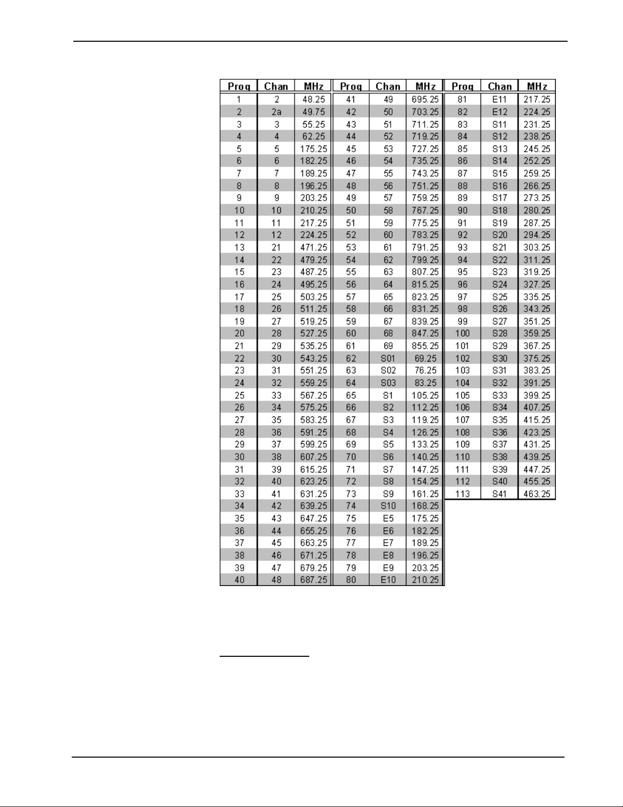
The <TV-Station> input sets the TV channel of the ST-TUNE. Valid values for TV
channels differ depending on the mode of the ST-TUNE. Channel numbers
increment by one.
The interlocked <F> outputs correspond to the current frequency of each band.
The <Sig-Strength> output is a stepped signal that indicates the strength of the FM
station frequency. The steps are decimal 0, 8191, 16382, 24573, 32764, 40955,
49146, 57337 or hexadecimal 0, 1FFF, 3FFE, 5FFD, 7FFC, 9FFB, BFFA,
DFF9. This signal applies only to FM frequencies.
NOTE: The <Srch> function described earlier works best when <Sig-Strength>
reads 24573d (5FFD hex) or above for low sensitivity (<Sense-Low>), or 40955
(9FFB hex) or above for high sensitivity (<Sense-High>).
The following table lists program numbers, channels, and corresponding
frequencies for international TV reception:
Symbol Guide – DOC. 6120 Crestron SIMPL
™
Windows® • 7
Page 14
Software Crestron SIMPL™ Windows
®
8 • Crestron SIMPL
Description
The STI-TUNE is the international version of Crestron's AM/FM/weather radio and
television tuner.
ST-TUNE (USA)
Signals
• Digital inputs: <Up>, <Dn>, <Func>, <AM>, <FM>, <WX> and <TV>
• Digital outputs: <Up-B>, <Dn-B>, <Func-B>, <AM-F>, <FM-F>, <WX-
F> and <TV-F>
™
Windows® Symbol Guide – DOC. 6120
Page 15

Crestron SIMPL™ Windows® Software
The <AM>, <FM>, <WX> (weather) and <TV> inputs set the ST-TUNE to the
corresponding band on the rising edge of the signal. Alternatively, the <Func>
input will cause the ST-TUNE to cycle through the AM, FM, WX, and TV bands
(in that order) with each rising edge of <Func>.
The <Up> and <Dn> inputs advance or reverse the radio or TV channel with each
rising edge of the signal. If either of the <Up> or <Dn> inputs remains high for a
period of time (as the result of a prolonged button press) the channel will continue
to change automatically for as long as the signal remains high.
The interlocked <B> (button) and <F> outputs provide the corresponding feedback
for each band.
• Digital inputs: <Mode>, <Pre>, <Tune>, <Srch>, <Sense-High> and
<Sense-Low>
• Digital outputs: <Mode-B>, <Pre-F>, <Tune-F>, <Srch-F>
The <Pre> (preset), <Tune> and <Srch> inputs set the ST-TUNE unit to the
corresponding mode on the rising edge of the signal. The <Pre> mode allows preset
radio or TV stations to be selected on the rising edge of <Up> or <Dn>. In <Tune>
mode, <Up> and <Dn> will increment or decrement settings by one unit.
In <Srch> mode, the setting jumps to the next available station on the rising edge of
<Up> or <Dn>. To improve the search function, the <Sense-High> and <Sense-
Low> inputs set the sensitivity of the ST-TUNE. <Sense-High> enables the STTUNE to pick up weaker stations.
The <Mode> input will cause the ST-TUNE to cycle through the preset, tune, and
search modes (in that order) with each rising edge of the signal.
The interlocked <F> signals provide the corresponding feedback for each mode.
• Digital inputs: <Mono>, <Mono-On> and <Mono-Off>
• Digital outputs: <Mono-B>, <Mono-On-F>, <Mono-Off-F> and <Stereo-
Detect>
The <Mono-Off> and <Mono-On> signals set the ST-TUNE to FM stereo or mono
on the rising edge of the signal. Alternatively, the <Mono> input toggles between
FM stereo and mono with each rising edge of the signal. The <Stereo-Detect>
signal is high whenever the current FM station is being received in stereo.
The interlocking <B> and <F> signals provide the corresponding feedback for each
mode.
• Digital inputs: <SAP-On> and <SAP-Off>
• Digital outputs: <SAP-On-F> and <SAP-Off-F>
The <SAP> inputs turn television SAP (Second Audio Program for foreign
language) reception on or off on the rising edge of the signal, with the interlocked
<F> signals providing the corresponding feedback.
• Digital input: <Disable-Lcl-Btns>
When this input is high, the local functionality of the front panel buttons is disabled.
• Digital inputs: <Off-Air>, <STD>, <IRC> and <HRC>
These are four modes for United States TV reception. In each mode, the channels
map to different frequencies. The mode changes on the rising edge of the next
frequency change.
• Analog inputs: <AM-Station>, <FM-Station>, <WX-Station> and <TVStation>
Symbol Guide – DOC. 6120 Crestron SIMPL
™
Windows® • 9
Page 16

Software Crestron SIMPL™ Windows
• Analog outputs: <AM-Station-F>, <FM-Station-F>, <WX-Station-F>,
<TV-Station-F> and <Sig-Strength>
The <AM-Station> input sets the AM frequency of the ST-TUNE. Valid AM
values increment by ten only and range from 530d through 1710d.
The <FM-Station> input sets the FM frequency of the ST-TUNE. Valid FM values
increment by five only and range from 8950d through 10790d, with an implied
decimal point two digits from the end. Thus, to specify FM station 102.7, <FM-
Station> must be set to 10270d.
The <WX> input sets the weather station frequency of the ST-TUNE. Valid
weather radio values increment by one only and range from 16240d through
16255d, with an implied decimal point two digits from the end. Thus, to specify
weather station 162.43, <WX> must be set to 16243d.
The <TV-Station> input sets the TV channel of the ST-TUNE. Valid values for TV
channels differ depending on the mode of the ST-TUNE. Channel numbers
increment by one.
The interlocked <F> outputs correspond to the current frequency of each band.
The <Sig-Strength> output is a stepped signal that indicates the strength of the FM
station frequency. The steps are decimal 0, 8191, 16382, 24573, 32764, 40955,
49146, 57337 or hexadecimal 0, 1FFF, 3FFE, 5FFD, 7FFC, 9FFB, BFFA,
DFF9. This signal applies only to FM frequencies.
®
NOTE: The <Srch> function described earlier works best when <Sig-Strength>
reads 24573d (5FFD hex) or above for low sensitivity (<Sense-Low>), or 40955
(9FFB hex) or above for high sensitivity (<Sense-High>).
Description
The ST-TUNE is an AM/FM/weather radio and television tuner.
ST-VC
Signals
• Four digital inputs: <mutea> through <mutec>, and <muteall>
• Nine analog inputs: <volA> through <volC>, <trebA> through <trebC>,
and <bassA> through <bassC>
Description
The ST-VC is a three-channel audio attenuator with settings for volume, tone
(bass/treble) and muting. Each channel (A through C) can have discrete ramp times,
scaling factors, preset levels, and so forth. Alternatively, multiple channels can have
the same settings to support stereo applications.
Each channel also has a corresponding muting relay with 104 dB attenuation. That
is, when any of the <muteA> through <muteC> inputs goes high, the muting circuit
provides a 104 dB drop from the current volume level. When a <mute> input goes
low, the volume setting returns to its previous level.
10 • Crestron SIMPL
The <muteall> input mutes all channels for as long as <muteall> remains high.
When <muteall> goes low, all channels return to their previous settings.
™
Windows® Symbol Guide – DOC. 6120
Page 17

Crestron SIMPL™ Windows® Software
Cresnet Camera Controllers
CNXFZ
Speed Key Name: cami2
Signals
• Serial input: <tx$>
• Digital inputs: <RTS>, <Iris>, <BREAK> and <Mode Set>
• Analog inputs: <foc_set>, <zoom_set>, <foc_rate>, <zoom_rate>,
<iris_rate> and <iris_set>
• Serial output: <rx$>
• Analog outputs: <foc_pos> and <zoom_pos>
Description
The CNXFZ controls the focus, zoom and iris (aperture) settings of a video camera
lens, in either position or rate mode. In position mode, the <set> inputs specify the
exact focus, zoom and iris settings. Whenever a <set> input changes value, the
camera will adjust to the new setting at maximum speed.
In rate mode, the <rate> inputs adjust these parameters at speeds relative to the
50% mark. That is, whenever a <rate> input equals 50% the corresponding setting
will hold steady and the camera lens will remain fixed. If a <rate> input goes above
or below 50%, the lens will adjust at a proportional speed until <rate> once again
equals 50% (or the lens has reached its limit). This means that in most applications
<rate> values of 25% and 75% represent half-speed, while values of 0% and 100%
represent the maximum speed of the lens.
NOTE: The position and rate modes can override each other; the "controlling"
mode is determined by whichever <set> or <rate> input last changes.
The <pos> outputs represent the current values for each setting (regardless of
whether the lens is in position or rate mode). These values can be stored and used to
define analog presets.
The <Iris> input opens or closes iris control contacts. This signal is similar to a
relay contact, and on most lenses can be used to toggle between automatic
(programmed) and manual control of the iris.
The <Mode Set> input is used only with Canon KTS or Fujinon MD, BMD series
lenses, which have an input that allows switching between rate and position modes.
Serial Data
Some cameras have serial COM ports that enable serial communication. For these
applications, <tx$> and <rx$> transmit data to and from the camera in whatever
protocol is specified for the camera in Configuration Manager. (This protocol will
be described in the manufacturer's documentation.)
The <RTS> (request to send) input is a hardware handshaking signal, and is
enabled only if the Hardware Handshake setting in Configuration Manager is set
to None. The <BREAK> signal is required by some devices, and interrupts serial
transmission by driving the transmit pin of the associated COM port low.
See also CPC-CAMI on page 12
Symbol Guide – DOC. 6120 Crestron SIMPL
™
Windows® • 11
Page 18

Software Crestron SIMPL™ Windows
CPC-2000
Signals
• Eight analog outputs: <pan_joy>, <tilt_joy>, <zoom_joy>, <foc_joy>,
<pan_spd>, <tilt_spd>, <zoom_spd> and <foc_spd>
Description
The CPC-2000A is a joystick-camera controller that consists of a touch screen with
dual joysticks and adjustable speed knobs. The outputs of the symbol must be
routed through an Analog Scaling Buffer about 50% symbol to drive the inputs of a
CPC-CAMI.
The <joy> outputs specify the pan (horizontal) and tilt (vertical) position of the
camera, as well as the focus and zoom settings. The <spd> outputs specify the
speed of the camera movement.
See also Analog Scaling Buffer about 50%, CPC-CAMI on page 12
CPC-CAMI
Signals
• Serial input: <tx$>
®
• Digital inputs: <RTS>, <Iris>, <BREAK>, <Mode Set>
• Analog inputs: <tilt_set>, <pan_set>, <foc_set>, <zoom_set> and
<iris_set>
• Analog inputs: <tilt_rate>, <pan_rate>, <foc_rate>, <zoom_rate>,
<iris_rate> and <speed_limit>
• Serial output: <rx$>
• Analog outputs: <tilt_pos>, <pan_pos>, <foc_pos> and <zoom_pos>
Description
The CPC-CAMI enables control of a video camera, in either position or rate mode.
In position mode, the <set> inputs specify the exact pan (horizontal) and tilt
(vertical) position of the camera, as well as the exact focus, zoom and iris (aperture)
settings. Whenever a <set> input changes value, the camera will adjust to the new
setting at maximum speed.
In rate mode, the <rate> inputs adjust these parameters at speeds relative to the 50%
mark. That is, whenever a <rate> input equals 50% the corresponding setting will
hold steady and the camera (or lens) will not move. If a <rate> input goes above or
below 50%, the camera will move at a proportional speed until <rate> once again
equals 50% (or the camera has reached its limit). This means that in most
applications <rate> values of 25% and 75% represent half-speed, while values of
0% and 100% represent the camera's maximum speed.
The <speed_limit> input permits the scaling of the pan/tilt speed. Speed limit does
not affect lens action.
12 • Crestron SIMPL
The position and rate modes can override each other; the "controlling" mode is
determined by whichever <set> or <rate> input last changes.
The <pos> outputs represent the current values for each setting (regardless of
whether the camera is in rate or position mode). These values can be stored and
used to define analog presets.
™
Windows® Symbol Guide – DOC. 6120
Page 19

Crestron SIMPL™ Windows® Software
The <Iris> input opens or closes iris control contacts. This signal is similar to a
relay contact, and on most lenses can be used to toggle between automatic
(programmed) and manual control of the iris.
The <Mode Set> input is used only with Canon KTS or Fujinon MD, BMD series
lenses, which have an input that allows switching between rate mode and position
mode.
Serial Data
Some cameras have serial COM ports that enable serial communication. For these
applications, <tx$> and <rx$> transmit data to and from the camera in whatever
protocol is specified for the camera in Configuration Manager. (This protocol will
be described in the manufacturer's documentation.)
The <RTS> (request to send) input is a hardware handshaking signal, and is
enabled only if the Hardware Handshake setting in Configuration Manager is set
to None. The <BREAK> signal is required by some devices, and interrupts serial
transmission by driving the transmit pin of the associated COM port low.
Cresnet I/O & Other Modules
BB/DA-1550CW
Signals
• One digital input: <unlatch>
• Five digital outputs: <unlatched>, <PanelPresent>, <Charging>,
<ChargeDone> and <ChargeFault>
Description
The BB/DA-1550CW is a docking assembly for the STX-1550CW compact color
touchpanel. On the rising edge of <unlatch>, the back box that supports the
touchpanel disengages for five seconds. (If the touchpanel is not physically
removed from the back box within that time, it will reattach to the docking
assembly.) The <unlatched> output is high whenever the back box is unlatched.
The <PanelPresent> output is high whenever the touchpanel is docked, and low
when the touchpanel is not docked.
The <Charging> output is high whenever the touchpanel is docked and charging.
The <ChargeDone> output is high whenever the touchpanel is docked and fully
charged.
The <ChargeFault> output goes high whenever there is a charge fault, i.e., a
problem with the hardware, contacts, or network voltage.
Symbol Guide – DOC. 6120 Crestron SIMPL
™
Windows® • 13
Page 20
Software Crestron SIMPL™ Windows
CNMK
Signals
• Two serial inputs: <data> and <keyout>
Description
The CNMK is a mouse/keyboard wedge, so called because it "wedges" between the
mouse or keyboard and the computer console. In this way, it allows the control
system to send commands to the PC, which the PC accepts as if it were coming
from the mouse or keyboard. The CNMK is typically used to facilitate boardroom
or classroom presentations. Both the <data> and <keyout> serial inputs are issued
from the control system to the PC.
The <data> input controls mouse functions and is usually driven by the CNWM
(wireless mouse) remote controller. This controller has customizable buttons for
right and left clicks, as well as a pressure sensitive thumb pad that is used to
position the cursor.
The <keyout> input controls the keyboard. Here the buttons on the CNWM can be
programmed to trigger keyboard functions.
The PC interface is designed to allow maximum flexibility in defining certain
keyboard operations. This is accomplished by having the keyboard return scan
codes rather than ASCII codes. Each key generates a "make" scan code when
pressed and a "break" scan code when released. The computer system then
interprets the scan codes to determine what operation to perform.
®
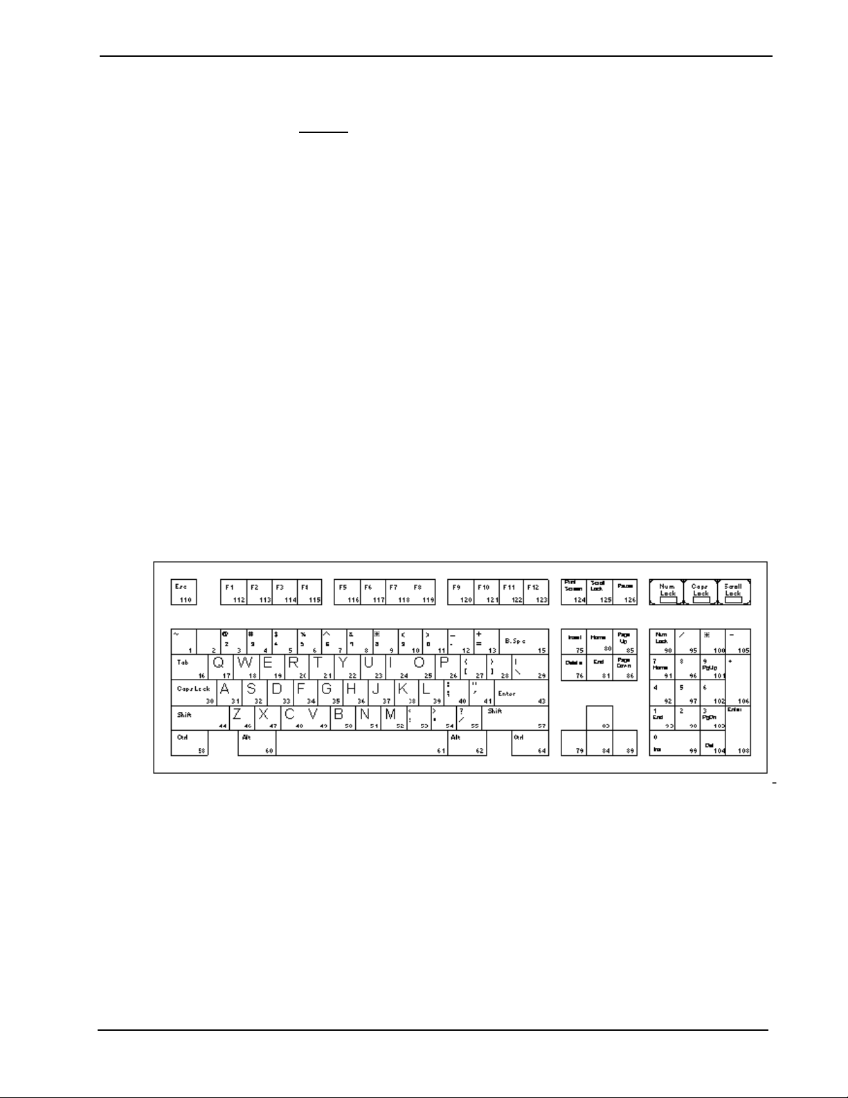
As shown below, each key on the keyboard is assigned a "Find" number that
corresponds to the Make and Break scan codes.
The following table lists the scan codes that apply to each key. For example, the "S"
key corresponds to the number 32. Thus, the Make scan code for this key is \x1B
and the Break scan code is \xF0\x1B.
14 • Crestron SIMPL
™
Windows® Symbol Guide – DOC. 6120
Page 21

Crestron SIMPL™ Windows® Software
See also CNWM on page 88, Mouse Simulator
Symbol Guide – DOC. 6120 Crestron SIMPL
™
Windows® • 15
Page 22

Software Crestron SIMPL™ Windows
CNSC-1A
Signals
• Five digital inputs: <pwr>, <fwd>, <rev>, <foc+> and <foc->
• Six digital outputs: <i1> through <i5> and <(AC) i6>
Description
The CNSC-1A is a slide projector interface. The <pwr> input sends main power to
the projector, while the <fwd> and <rev> inputs advance and reverse the projector's
slide mechanism. The two <foc> inputs adjust the focus settings.
The CNSC-1A also accepts five input closures. The <(AC) i6> input goes high
whenever the AC OUT switch on the front of the unit is pressed.
CNTV
Signals
• One serial input: <TX$>
• One serial output: <RX$>
Description
®
The CNTV is used in SchoolNet or stand-alone applications to control TVs and
other devices. The serial protocol that the CNTV requires differs depending on the
application. This protocol must be custom-programmed into the firmware by
Crestron.
ST-COM
The ST-COM provides two serial COM ports (A and B) that enable RS-232, RS424, and RS-485 communication.
Each port has a built-in serial driver with communication settings that must be
specified in Configuration Manager. These settings define the protocol that a
controlled serial device expects, and include the speed of data transmission (baud
rate), error checking (parity), and the number of data bits and stop bits. In addition,
a device might require hardware or software handshaking, which controls the flow
of data between two devices. The exact protocol will be described in the
manufacturer's documentation.
The Crestron database includes numerous serial devices, with default logic and preconfigured communication settings, that are compatible with the ports on the ST-
COM. These devices are identified in Configuration Manager by a
Simply drag the serial device to one of the ports on the ST-COM and click Yes
when prompted to replace the built-in serial driver for that port. In most cases, the
default logic should be loaded as well.
The ST-COM symbol detail requires no programming.
icon.
16 • Crestron SIMPL
To program a serial driver expand the ST-COM by clicking the plus sign in
Program View. Then drag the desired serial driver to Detail View.
See also Serial Drivers
™
Windows® Symbol Guide – DOC. 6120
Page 23

Crestron SIMPL™ Windows® Software
ST-LT
ST-LT is an interface to Lutron's GRAFIK EYE™ system. It provides two serial
COM ports (A and B) with built-in serial drivers. Port A (Lutron Port) connects
directly into the Lutron Mux Link, whereas Port B (9600 Port) is an RS-232 port
(set to a baud rate of 9600) for interfacing to a PC running Lutron control software.
The ST-LT symbol detail requires no programming.
To program a serial driver expand the ST-COM by clicking the plus sign in
Program View. Then drag the desired serial driver to Detail View.
See also Serial Drivers
ST-IO
Signals
• Eight digital inputs: <relay1> through <relay8>
• Four digital outputs: <i1> through <i4>
Description
The ST-IO provides eight isolated relays for controlling low voltage contact closure
devices such as drapes, screens and lifts. It also provides four local digital outputs.
When a <relay> signal goes high, the corresponding relay closes for as long as the
signal remains high. When the signal goes low, the relay opens. If a signal is
undefined, the relay is open.
The four local <i> outputs can function in either closure or voltage mode. In closure
mode (the default setting), an <i> signal goes high whenever the interface detects
the presence of a switch or relay closure to ground. In voltage mode, the <i> signal
goes high when it detects the presence of an active voltage (voltages > 2.5V = logic
1, and voltages < 1.5V = logic low).
Cresnet Power Control Modules
CNECI-4A
Signals
• Four digital inputs: <relay1> through <relay4>
• Eight digital outputs: <i1> through <i8>
Description
The CNECI-4A is a wall-mounted interface for controlling low voltage contact
closure devices such as drapes, screens and lifts. It provides four isolate relays,
typically driven by a CT-3000 touchpanel, and eight local digital outputs.
When a <relay> signal goes high, the corresponding relay closes for as long as the
signal remains high. When the signal goes low, the relay opens. If a signal is
undefined, the relay is open.
The eight <i> outputs can function in either closure or voltage mode. In closure
mode (the default setting), an <i> signal goes high whenever the interface detects
the presence of a switch or relay closure to ground. In voltage mode, the <i> signal
goes high when it detects the presence of an active voltage (voltages > 2.5V = logic
1, and voltages < 1.5V = logic low).
Symbol Guide – DOC. 6120 Crestron SIMPL
™
Windows® • 17
Page 24

Software Crestron SIMPL™ Windows
ST-PC
Signals
• Two digital inputs: <pwrA> and <pwrB>
• Two digital outputs: <pressA> and <pressB>
Description
The ST-PC incorporates two independent AC sockets into one unit. The <pwr>
inputs supply power to a device; the <press> outputs go high whenever the
corresponding push button on the ST-PC is pressed.
Cresnet Sensing Modules
®
CNTS-N
Signal
Description
The CNTS-N detects and measures ambient room temperature. Typically, the
temperature reading is transmitted to a touchpanel via an Analog Scaler symbol.
The various gauge objects available in VT Pro-e can then display the value in a
number of formats.
• One analog output: <temp>
ST-CS
Signals
• Four digital outputs: <Full Sense 1>, <Full Sense 2>, <Partial Sense 1>
and <Partial Sense 2>
Description
The ST-CS incorporates two independent current sensors in one unit. The <Full
Sense> outputs go high whenever the average current drawn by a monitored device
exceeds the upper threshold that is specified for that device.
The <Partial Sense> outputs go high when the current drawn by the device exceeds
an intermediate threshold.
ST-VS
18 • Crestron SIMPL
Signals
• Digital outputs: <sense1> through <sense4>
Description
The ST-VS detects the presence of up to four discrete base band video signals.
Whenever a video signal is detected from a monitored device, such as a VCR or
television tuner, the corresponding <sense> output goes high. This signal can then
trigger a relay to lower a screen, for example, or turn lights on or off in a room.
™
Windows® Symbol Guide – DOC. 6120
Page 25
Crestron SIMPL™ Windows® Software
Cresnet Video Modules
CNX-PVID8x3
Signals
• 3 levels of 8 analog inputs: <Src-For-Out-1-Level-N> through <Src-For-
Out-8-Level-N>
• 3 levels of 16 digital outputs: <Sense-In-1-Level-N> through <Sense-In-
16-Level-N>
Description
The CNX-PVID8x3 is a video matrix switcher that selects video sources and
distributes the video to up to 8 outputs. It provides 3 levels, or tiers, of 16 RCA
inputs and 3 levels of 8 RCA outputs. It also provides 8 RJ45 connectors that enable
CAT5 cabling to Crestron's CNXRMC and CNXRMCLV room solution boxes.
The <Src-For-Out-M-Level-N> analogs select the video source for an output as
follows: the signal is set (typically via an Analog Initialize symbol) to a value that
corresponds to the video source. This value can range from 1-32, depending on the
hardware configuration. If a signal is set to 0, no video is sent. <Out-M> specifies
the output (1-8), while <Level-N> gives the level (1-3).
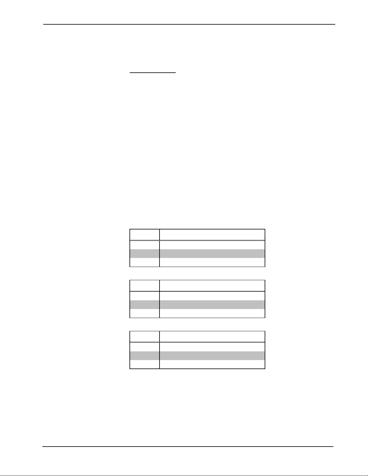
The following tables give the valid range of analog values for three different
hardware configurations.
Standard Configuration (maximum 16 sources)
Level Allowable range of analog values
1 0 - 16
2 0 - 16
3 0 - 16
J13 Configuration (Levels 1 and 3 are jumpered together - maximum 32 sources)
Level Allowable range of analog values
1 0 - 32 (17-32 represent inputs on Level 3)
2 0 - 16
3 unused
J13S Configuration (Level 3 is split - maximum 24 sources)
Level Allowable range of analog values
1 0 - 24 (17-24 represent inputs on Level 3)
2 0 - 16
3 0, 9 - 16
Example 1 (Standard Configuration): A component video source is connected to
input 3 (Levels 1, 2, and 3). To distribute video to output 5, the following analogs
must be set to 3:
<Src-For-Out-5-Level-1> = 3
<Src-For-Out-5-Level-2> = 3
<Src-For-Out-5-Level-3> = 3
Symbol Guide – DOC. 6120 Crestron SIMPL
™
Windows® • 19
Page 26

Software Crestron SIMPL™ Windows
Example 2 (Standard Configuration): A composite video source is connected to
input 15 (Level 1). To distribute video to outputs 2, 5, and 7, the following analogs
must be set to 15:
<Src-For-Out-2-Level-1> = 15
<Src-For-Out-5-Level-1> = 15
<Src-For-Out-7-Level-1> = 15
Example 3 (Standard Configuration): An S video source is connected to input 12
(Levels 1 and 2). To distribute video to outputs 1 and 4, the following analogs must
be set to 12:
<Src-For-Out-1-Level-1> = 12
<Src-For-Out-1-Level-2> = 12
<Src-For-Out-4-Level-1> = 12
<Src-For-Out-4-Level-2> = 12
Example 4 (J13 Configuration): A composite video source is connected to input
27. To distribute video to outputs 2 and 3, the following analogs must be set to 27
(16 + 11):
<Src-For-Out-2-Level-1> = 27
<Src-For-Out-3-Level-1> = 27
®
The CNX-PVID provides 16 built-in video sensors that can be used for
synchronization or diagnostics. The <Sense-In> outputs will go high whenever the
presence of a video signal is detected at the corresponding input and level.
CNXPVID8x4
Signals
• 4 levels of 8 analog inputs: <Src-For-Out-1-Level-N> through <Src-For-
Out-8-Level-N>
• 4 levels of 16 digital outputs: <Sense-In-1-Level-N> through <Sense-In-
16-Level-N>
Description
The CNX-PVID8x4 is a video matrix switcher that selects video sources and
distributes the video to up to 8 outputs. It provides all the functionality of the CNXPVID8x3, with the additional capability of distributing digital audio.
The CNX-PVID8x4 provides 4 levels, or tiers, of 16 RCA inputs and 4 levels of 8
RCA outputs. It also provides 8 RJ45 connectors that enable CAT5 cabling to
Crestron's CNXRMC and CNXRMCLV room solution boxes.
The <Src-For-Out-M-Level-N> analogs select the video source for an output as
follows: the signal is set (typically via an Analog Initialize symbol) to a value that
corresponds to the video source. This value can range from 1-32, depending on the
hardware configuration. If a signal is set to 0, no video is sent. <Out-M> specifies
the output (1-8), while <Level-N> gives the level (1-4).
20 • Crestron SIMPL
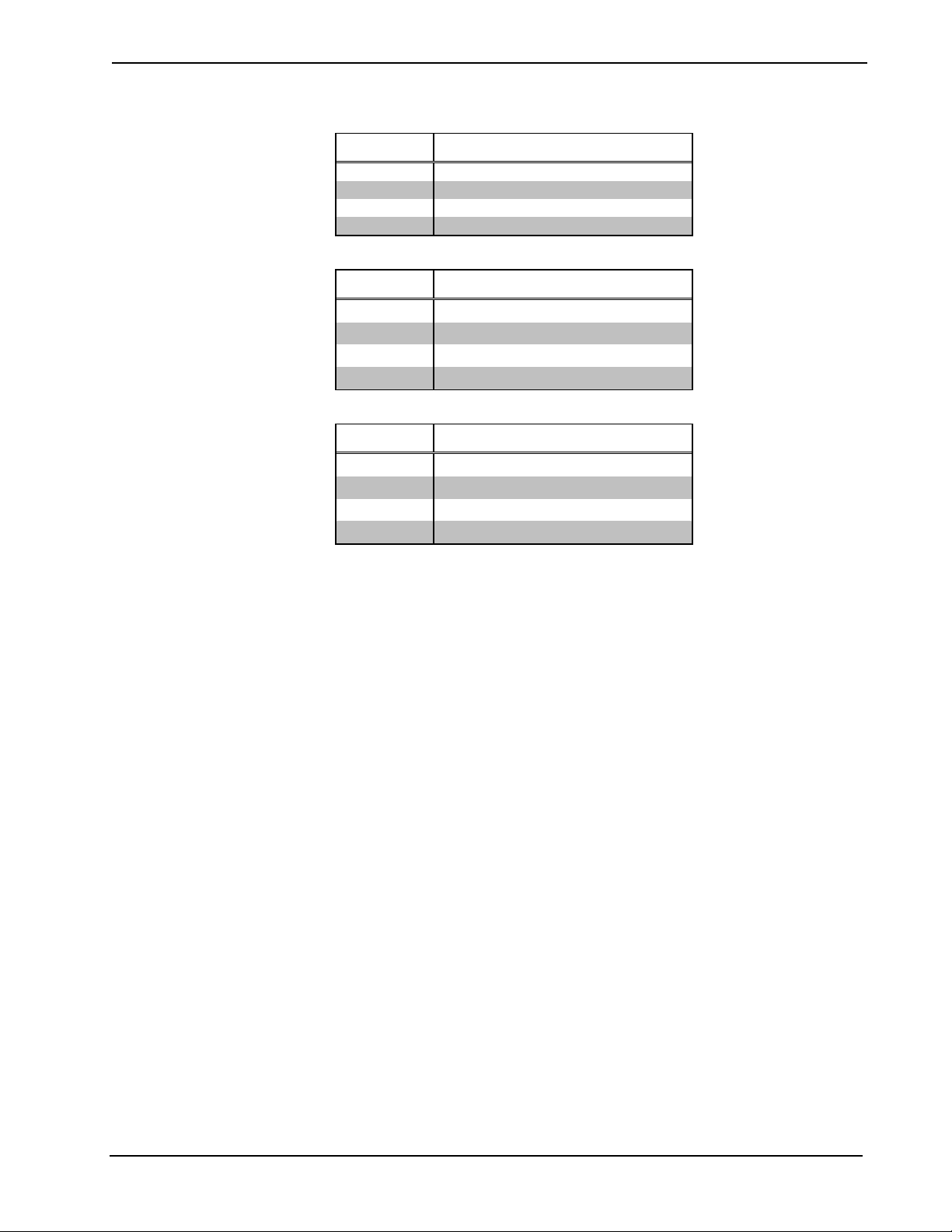
The following tables give the valid range of analog values for three different
hardware configurations.
™
Windows® Symbol Guide – DOC. 6120
Page 27
Crestron SIMPL™ Windows® Software
Standard Configuration (maximum 16 sources)
Level Allowable range of analog values
1 0 - 16
2 0 - 16
3 0 - 16
4 0 - 16
J13 Configuration (Levels 1 and 3 are jumpered together - maximum 32 sources)
Level Allowable range of analog values
1 0 - 32 (17-32 represent inputs on Level 3)
2 0 - 16
3 unused
4 0 - 16
J13S Configuration (Level 3 is split - maximum 24 sources)
Level Allowable range of analog values
1 0 - 24 (17-24 represent inputs on Level 3)
2 0 - 16
3 0, 9 - 16
4 0 - 16
Example 1 (Standard Configuration): A component video source with digital
audio is connected to input 3 (Levels 1, 2, 3 and 4). To distribute video and digital
audio to output 5, the following analogs must be set to 3:
<Src-For-Out-5-Level-1> = 3
<Src-For-Out-5-Level-2> = 3
<Src-For-Out-5-Level-3> = 3
<Src-For-Out-5-Level-4> = 3
Example 2 (Standard Configuration): A composite video source with no digital
audio is connected to input 15 (Level 1). To distribute video to output 2, the
following analogs must be set to 15:
<Src-For-Out-2-Level-1> = 15
Example 3 (Standard Configuration): An S video source with digital audio is
connected to input 12 (Levels 1, 2 and 4). To distribute video and digital audio to
output 1, the following analogs must be set to 12:
<Src-For-Out-1-Level-1> = 12
<Src-For-Out-1-Level-2> = 12
<Src-For-Out-1-Level-4> = 12
Example 4 (J13 Configuration): A composite video source with digital audio is
connected to input 27. To distribute video and digital audio to output 3, the
following analogs must be set to the corresponding values:
<Src-For-Out-3-Level-1> = 27
<Src-For-Out-2-Level-4> = 11
The CNX-PVID provides 16 built-in video sensors that can be used for
synchronization or diagnostics. The <Sense-In> outputs will go high whenever the
presence of a video signal is detected at the corresponding input and level.
Symbol Guide – DOC. 6120 Crestron SIMPL
™
Windows® • 21
Page 28

Software Crestron SIMPL™ Windows
CNX-RMC
The CNX-RMC room solution box is typically used in video distribution
applications with the CNX-PVID8. The CNX-RMC receives video and digital
audio via CAT5 cabling and then distributes these inputs to local outputs. It also
provides a current sensor, 4 infrared (IR) ports and 1 RS-232 port for controlling
local devices.
The CNX-RMC symbol detail requires no programming.
To program a control card or device driver, expand the CNX-RMC by clicking the
plus sign in Program Manager, then drag the device to Detail View.
CNX-RMCLV
The CNX-RMCLV room solution box contains an 8x8 video matrix switcher, and is
typically used with the CNX-PVID8 in video distribution applications.
The CNX-RMCLV receives video and digital audio from the CNX-PVID8 via
CAT5 cabling. It can also receive analog audio via CAT5 from a CNX-BIPAD8.
And it can receive video/digital audio and analog audio from local sources via
standard RCA connections. The built-in Audio/Video Matrix Control module
distributes these inputs to local outputs.
®
The CNX-RMCLV also provides 4 current sensors, 4 infrared (IR) ports and 1 RS232 port for controlling local devices. Finally, it provides outputs for directing
video and digital audio back to the head end.
The CNX-RMCLV symbol detail requires no programming.
To program a control card or device driver, expand the CNX-RMCLV by clicking
the plus sign in Program Manager, then drag the device to Detail View.
CNXVGA
Description
The CNXVGA enables the display of RGB video on Crestron VT-3500(L)
touchpanels.
The CNXVGA accepts RGB video in most standard formats (VGA, SVGA, MAC,
etc.) and outputs either composite or S video.
Signals
• Digital inputs: <RGB>, <Video> and <out_disable>
• Digital outputs: <RGB_on>, <Video_on>
The <RGB> and <Video> inputs select the video format of the source, on the rising
edge of the signal, with the <on> outputs providing the corresponding feedback.
The <out_disable> signal cuts off the video output for as long as the signal is high.
• Digital inputs: <in_adj> and <out_adj>
22 • Crestron SIMPL
• Digital inputs: <up>, <down>, <left>, <right>, <width+>, <width->,
<height+>, <height-> and <save_settings>
• Digital inputs: <in_recenter> and <out_recenter>
The <in_adj> input enables the user to position and size the RGB image on the
touch screen. The <out_adj> input is used to define the viewing area for
applications where the target device is not a VT-3500(L) touchpanel. When either
of these inputs is high, the positional inputs (<up>, <down>, <left>, <right>,
™
Windows® Symbol Guide – DOC. 6120
Page 29

Crestron SIMPL™ Windows® Software
<width> and <height>) will adjust the display in single steps with each rising edge
of the input.
Once the desired dimensions are obtained, a rising edge of the <save_settings>
input will store the parameters into a preset memory location. (This location is
specified by the <preset#> output, discussed later.)
During adjustment of the dimensions, the <in_recenter> input re-synchronizes the
CNXVGA with the input signal, should the image move out of the viewing area.
The input triggers a "best guess" adjustment based on the detected incoming signal.
The <out_recenter> input simply restores the <out_adj> factory settings for the
VT-3500.
• Digital input: <autodetect_off>
By default, the CNXVGA is set to auto detect all incoming signals. In the case of a
stand-alone application this is needed to sense the incoming signal and adjust to its
parameters on the fly. If an application requires discrete preset selections, the
<autodetect_off> input should be set to 1.
• Digital inputs: <preset_1> through <preset_25>, and <clear_preset>
• Digital output: <preset_empty>
To use discrete preset selections, the <autodetect_off> input must be low. The
<clear_preset> input can be used to erase all of the settings in the selected preset
memory. The <preset_empty> output goes high whenever the presets have been
cleared.
• Analog outputs: <preset#>, <vfreq> and <hfreq>
The <preset#> output gives the value of the currently selected preset memory
location, while the <freq> outputs report the values of the current horizontal and
vertical input frequencies.
Cresnet Remote Processing
CN-TVAV
The CN-TVAV controls devices such as TVs, VCRs, DVD players, and switchers
in one of three processing modes: local, remote, or mixed.
In local processing mode, the CN-TVAV operates as an independent control system,
uploaded with a SIMPL Windows logic program to control network devices.
In remote processing mode, the CN-TVAV operates in a master/slave arrangement
whereby the unit is controlled by another control system, typically a CNMSX-Pro.
Here the CN-TVAV is a peripheral device within the program of the host control
system. Thus all the functionality of the unit is accessed via the host control system,
with no programming in the CN-TVAV itself. Remote processing makes five slots
available on the CN-TVAV.
Mixed processing mode, as the name suggests, combines local processing and
remote processing. That is, some functionality is programmed into the unit whereas
other commands come from a host control system. For example, the Versiports
might be used to control equipment via the program in the CN-TVAV, while the IR
Port might be accessed by the host control system (with no IR driver in the CNTVAV). Mixed processing makes three slots available on the CN-TVAV.
The CN-TVAV symbol detail requires no programming.
To program a built-in card or device driver expand the CN-TVAV by clicking the
plus sign in Program View. Then drag the device to Detail View.
Symbol Guide – DOC. 6120 Crestron SIMPL
™
Windows® • 23
Page 30

Software Crestron SIMPL™ Windows
CN-ISC
Signals
• Digital inputs: <dig-o1> through <dig-o999>
• Analog inputs: <an_o1> through <an_o254>
• Serial inputs: <serial-o1> through <serial-o127>
• Digital outputs: <dig-i1> through <dig-i999>
• Analog outputs: <an_i1> through <an_i254>
• Serial outputs: <serial-i1> through <serial-i127>
Description
The CN-ISC symbol is an Intersystem Communications (ISC) symbol that enables
communication between a CN-TVAV and another control system.
Processing Modes
The CN-TVAV controls devices such as TVs, VCRs, DVD players, and switchers
in one of three processing modes: local, remote, or mixed. The CN-ISC symbol is
available when the CN-TVAV operates in either local or mixed processing mode; it
is not needed when the unit operates in remote processing mode.
®
In local processing mode, the CN-TVAV operates as an independent control
system, uploaded with a SIMPL Windows logic program to control network
devices. Depending on the application, the CN-TVAV may or may not have to
communicate with another control system. If it does need to communicate with
another control system, then 16 discrete symbols (channels) are available on slot 05
of the unit.
In remote processing mode, the CN-TVAV operates in a master/slave arrangement
whereby the unit is controlled by another control system, typically a CNMSX-Pro.
Here the CN-TVAV is a peripheral device within the program of the host control
system. Thus all the functionality of the unit is accessed via the host control system,
with no programming in the CN-TVAV itself. As described previously, the CN-ISC
symbol is not needed in remote processing mode, since in this instance the CENTVAV is simply another controlled network device.
Mixed processing mode, as the name suggests, combines local processing and
remote processing. That is, some functionality is programmed into the unit whereas
other commands come from a host control system. For example, the Versiports
might be used to control equipment via the program in the CN-TVAV, while the IR
Port might be accessed by the host control system (with no IR driver in the CNTVAV). In these applications, the host must communicate with the CN-TVAV via
the CN-ISC symbol that is built into slot 05 of the device. The 16 channels will be
visible in Program Manager.
Symbol Description
An ISC symbol can have practically any number and combination of digital, analog,
and serial inputs and outputs. Whenever any of its inputs changes value, the symbol
transmits this information across the network. On the receiving end, the data comes
into a second ISC symbol, which drives its outputs to the corresponding values.
24 • Crestron SIMPL
The inputs of an ISC symbol are mapped to the outputs of another ISC symbol as
follows: all signals are internally numbered by position, starting at 0. Thus the index
of the first defined signal is 0, the index of the second is 1, the third, 2, and so forth.
Since signals are mapped by index, it is not necessary for input/output "pairs" to
™
Windows® Symbol Guide – DOC. 6120
Page 31

Crestron SIMPL™ Windows® Software
have the same signal name. That is, an input signal at index 25 will always be
mapped to an output signal at index 25, regardless of what the signal names are.
See also Intersystem, Ethernet Intersystem Communication on page 35, Virtual
Communication Port on page 41
TVAVIO
The TVAVIO is built into the CN-TVAV and CEN-TVAV. It provides a power
sensor and four Versiports, each of which can function as a digital input, digital
output or analog input. Each Versiport has a corresponding pull-up resistor.
Signals
• Power Sensor: <PowerSense>
Versiports
Digital output mode
• Digitals: <o1> through <o4>
Digital input mode
• Digitals: <i1> through <i4>
Analog input mode
• Analogs: <i1> through <i4>
• One parameter: <backlash>
All Versiport modes
• For each Versiport, one corresponding pull-up resistor: <pu-disable1>
through <pu-disable4>
Description
The following diagram shows the internal configuration of a Versiport.
+5V
2K
pullup1
o1
S1-A
S1-B
VersiPort 1
Used for analog input.
Can be either a voltage
A
source or resistive load.
Digital Output Mode
When a Versiport is operating in digital output mode, the output pin will be shorted
to ground on the rising edge of the corresponding <o> signal (switch S1-B in the
above diagram will be closed). When <o> goes low, the output pin is driven to a
value of +5V (switch S1-B is open).
This behavior can be modified by driving the corresponding <pu-disable> signal
high, although this is not recommended since it will cause the output pin to float
when <o> goes low.
Symbol Guide – DOC. 6120 Crestron SIMPL
™
Windows® • 25
Page 32

Software Crestron SIMPL™ Windows
Example 1 (recommended): <pu-disable1> is driven low or left undefined. When
<o1> goes low, Versiport 1 is at +5V. When <o1> goes high, Versiport 1 is shorted
to ground.
Example 2 (not recommended): <pu-disable1> is driven high. When <o1> goes
low, Versiport 1 is floating. When <o1> goes high, Versiport 1 is shorted to ground.
Digital Input Mode
When a Versiport is operating in digital input mode, the corresponding <i> signal
will go high whenever the TVAVIO detects that the Versiport is shorted to ground
(threshold < +2.5V). Note that here, as with digital output mode, the corresponding
pull-up resistor should be enabled. That is, <pu-disable> should be given the signal
name 0 or left undefined; otherwise the input will always read as logic low.
Example: When Versiport 3 is shorted to ground, <i3> will go high. When
Versiport 3 is not shorted to ground, <i3> will go low (so long as <pu-disable3>
equals 0 or is undefined).
Analog Input Mode
In analog input mode, the Versiport is typically tied to a resistive load (such as a
humidity sensor) or a voltage source (both can be represented by box "A" in the
diagram).
®
When a resistive load is tied to a Versiport, the corresponding pull-up resistor must
be enabled (again, this means that <pu-disable> should be given the signal name 0
or left undefined). This creates a voltage divider and provides a varying voltage
level (based on the current resistance of the sensor) for the TVAVIO to read.
Example: A resistive humidity sensor is tied to Versiport 1 (and <pu-disable1> is
low or undefined). <ain1> will assume the corresponding analog value.
When a voltage source is tied to a Versiport, the corresponding pull-up resistor
should be disabled (the only case where the default setting should be overridden).
This allows the TVAVIO to read the value of the voltage source directly.
Example: A voltage source is tied to Versiport 1 and <pu-disable1> is given the
signal name 1. <ain1> will assume the corresponding analog value (ranging from 0
to 65535, or 0 to +10V on the input pin).
The TVAVIO does not propagate all changes in the analog values of its Versiports,
since this can lead to undesirable results if the input source is not clean or has jitter.
Rather, the <backlash> parameter specifies a hysteresis value, such that if the
current level changes direction, the new value will not be reported until it changes
by <backlash>. (If no <backlash> parameter is specified the default value is 1%.)
Example: A voltage source is placed on Versiport 1 and <backlash> equals 1%.
The input voltage drops to 4.0 volts from some higher voltage. <i1> will assume a
value of 4. If the voltage should then rise, the value of <i1> will not change until
the voltage level reaches 4.1 volts.
26 • Crestron SIMPL
™
Windows® Symbol Guide – DOC. 6120
Page 33

Crestron SIMPL™ Windows® Software
AV2 Remote Processing
The AV2, like all 2-Series control systems, operates in one of two processing
modes: local or remote.
In local processing mode, the AV2 operates as an independent control system,
uploaded with a SIMPL Windows logic program to control network devices.
In remote processing mode, the AV2 operates in a master/slave arrangement
whereby the unit is controlled by another control system such as a PRO2. Here the
AV2 is a peripheral device within the program of the host control system. Thus all
the functionality of the unit is accessed via the host control system, with no
programming in the AV2 itself. Remote processing makes three slots available on
the AV2.
The AV2 symbol detail requires no programming.
To program a built-in card or device driver, expand the AV2 by clicking the plus
sign in Program View. Then drag the device from a slot to Detail View.
CP2 Remote Processing
The CP2, like all 2-Series control systems, operates in one of two processing
modes: local or remote.
In local processing mode, the CP2 operates as an independent control system,
uploaded with a SIMPL Windows logic program to control network devices.
In remote processing mode, the CP2 operates in a master/slave arrangement
whereby the unit is controlled by another control system such as a PRO2. Here the
CP22 is a peripheral device within the program of the host control system. Thus all
the functionality of the unit is accessed via the host control system, with no
programming in the CP22 itself. Remote processing makes three slots available on
the CP2.
The CP2 symbol detail requires no programming.
To program a built-in card or device driver, expand the CP2 by clicking the plus
sign in Program View. Then drag the device from a slot to Detail View.
CNX-DVP4
The CNX-DVP4, like all 2-Series control systems, operates in one of two
processing modes: local or remote.
In local processing mode, the DVP4 operates as an independent control system,
uploaded with a SIMPL Windows logic program to control network devices.
In remote processing mode, the DVP4 operates in a master/slave arrangement
whereby the unit is controlled by another control system such as a PRO2. Here the
DVP4 is a peripheral device within the program of the host control system. Thus all
the functionality of the unit is accessed via the host control system, with no
programming in the DVP4 itself. Remote processing makes two slots available on
the DVP4.
The DVP4 symbol detail requires no programming.
To program a built-in card or device driver, expand the DVP4 by clicking the plus
sign in Program View. Then drag the device from a slot to Detail View.
Symbol Guide – DOC. 6120 Crestron SIMPL
™
Windows® • 27
Page 34

Software Crestron SIMPL™ Windows
PAC2 Remote Processing
The PAC2, like all 2-Series control systems, operates in one of two processing
modes: local or remote.
In local processing mode, the PAC2 operates as an independent control system,
uploaded with a SIMPL Windows logic program to control network devices.
In remote processing mode, the PAC2 operates in a master/slave arrangement
whereby the unit is controlled by another control system such as a PRO2. Here the
PAC2 is a peripheral device within the program of the host control system. Thus all
the functionality of the unit is accessed via the host control system, with no
programming in the PAC2 itself. Remote processing makes three slots available on
the PAC2.
The PAC2 symbol detail requires no programming.
To program a built-in card or device driver, expand the PAC2 by clicking the plus
sign in Program View. Then drag the device from a slot to Detail View.
PRO2 Remote Processing
The PRO2, like all 2-Series control systems, operates in one of two processing
modes: local or remote.
®
In local processing mode, the PRO2 operates as an independent control system,
uploaded with a SIMPL Windows logic program to control network devices.
In remote processing mode, the PRO2 operates in a master/slave arrangement
whereby the unit is controlled by a control system such as another PRO2. Here the
PRO2 is a peripheral device within the program of the host control system. Thus all
the functionality of the unit is accessed via the host control system, with no
programming in the PRO2 itself. Remote processing makes three slots available on
the PRO2.
The PRO2 symbol detail requires no programming.
To program a built-in card or device driver, expand the PRO2 by clicking the plus
sign in Program View. Then drag the device from a slot to Detail View.
RACK2 Remote Processing
The RACK2, like all 2-Series control systems, operates in one of two processing
modes: local or remote.
In local processing mode, the RACK2 operates as an independent control system,
uploaded with a SIMPL Windows logic program to control network devices.
In remote processing mode, the RACK2 operates in a master/slave arrangement
whereby the unit is controlled by another control system such as a PRO2. Here the
RACK2 is a peripheral device within the program of the host control system. Thus
all the functionality of the unit is accessed via the host control system, with no
programming in the RACK2 itself. Remote processing makes three slots available
on the RACK2.
28 • Crestron SIMPL
The RACK2 symbol detail requires no programming.
To program a built-in card or device driver, expand the RACK2 by clicking the plus
sign in Program View. Then drag the device from a slot to Detail View.
™
Windows® Symbol Guide – DOC. 6120
Page 35

Crestron SIMPL™ Windows® Software
Ethernet Control Modules
Ethernet Modules (Crestron)
CEN-CN
The CEN-CN provides two Cresnet ports (represented by slot 05) that enable
communication with all Cresnet devices, and one LAN port that connects to the
control system via Ethernet. In this way, the CEN-CN provides Ethernet
connectivity between local Cresnet devices and a remotely located control system.
The CEN-CN symbol detail requires no programming.
To program a Cresnet device, expand the CEN-CN by clicking the plus sign in
Program View. Then expand the Remote Cresnet Device symbol, which also
requires no programming, and drag the device to Detail View.
CEN-COM
The CEN-COM provides two serial COM ports (A and B) that enable RS-232 or
RS-422 communication, and one LAN port that connects to the control system via
Ethernet.
Each COM port has a built-in serial driver with communication settings that must
be specified in Configuration Manager. These settings define the protocol that a
controlled serial device expects, and include the speed of data transmission (baud
rate), error checking (parity), and the number of data bits and stop bits. In addition,
a device might require hardware or software handshaking, which controls the flow
of data between two devices. The exact protocol will be described in the
manufacturer's documentation.
The Crestron database includes numerous serial devices, with default logic and preconfigured communication settings that are compatible with the ports on the COM
card. These devices are identified in Configuration Manager by a
drag the serial device to one of the ports on the COM card and click Yes when
prompted to replace the built-in serial driver for that port. If desired, the default
logic can be loaded as well.
The CEN-COM symbol detail requires no programming.
To program a serial driver expand the CEN-COM by clicking the plus sign in
Program View. Then drag the desired serial driver to Detail View.
See also Serial Drivers
icon. Simply
CEN-IO
The CEN-IO provides eight relays and eight Versiports. Each Versiport has a
corresponding pull-up resistor, and can function as a digital input, a digital output or
an analog input.
Relays
• Eight relays: <relay1> through <relay8>
• For each relay, one corresponding feedback signal: <relay1-f> through
<relay8-f>
Symbol Guide – DOC. 6120 Crestron SIMPL
™
Windows® • 29
Page 36

Software Crestron SIMPL™ Windows
Versiports
Digital output mode
• Digitals: <o1> through <o8>
• For each digital, one corresponding feedback signal: <o1-f> through <o8-
f>
Digital input mode
• Digitals: <i1> through <i8>
Analog input mode
• Analogs: <ain1> through <ain8>
• For each analog, one corresponding minimum change value:
<MinChange1> through <MinChange8>
• For each minimum change value, one corresponding feedback signal:
<MinChange1-f> through <MinChange8-f>
All Versiport modes
• For each Versiport, one corresponding pull-up resistor: <pullup1-dis>
through <pullup8-dis>
®
• For each resistor, one corresponding feedback signal: <pullup1-dis-f>
through <pullup8-dis-f>
Description
The CEN-IO provides 8 isolated relays for controlling low-voltage contact closure
devices such as drapes, screens and lifts.
When a <relay> signal goes high, the corresponding relay closes for as long as the
signal remains high. When the signal goes low, the relay opens. If a signal is
undefined, the relay is open.
The following diagram shows the internal configuration of a Versiport.
+5V
2K
pullup1
o1
S1-A
S1-B
VersiPort 1
Used for analog input.
Can be either a voltage
A
source or resistive load.
30 • Crestron SIMPL
Digital Output Mode
When a Versiport is operating in digital output mode, the output pin will be shorted
to ground on the rising edge of the corresponding <o> signal (switch S1-B in the
above diagram will be closed). When <o> goes low, the output pin is driven to a
value of +5V (switch S1-B is open).
™
Windows® Symbol Guide – DOC. 6120
Page 37

Crestron SIMPL™ Windows® Software
This behavior can be modified by driving the corresponding <pullup1-dis> signal
high, although this is not recommended since it will cause the output pin to float
when <o> goes low.
Example 1 (recommended): <pullup1-dis> is driven low or left undefined. When
<o1> goes low, Versiport 1 is at +5V. When <o1> goes high, Versiport 1 is shorted
to ground.
Example 2 (not recommended): <pullup1-dis> is driven high. When <o1> goes
low, Versiport 1 is floating. When <o1> goes high, Versiport 1 is shorted to ground.
Each signal <o1> through <o8> has corresponding feedback <o1-f> through <o8-f>
that is driven by the CEN-IO. Feedback is provided because the CEN-IO can accept
commands from multiple control systems.
Digital Input Mode
When a Versiport is operating in digital input mode, the corresponding <i> signal
will go high whenever the CEN-IO detects that the Versiport is shorted to ground
(threshold < +2.5V). Note that here, as with digital output mode, the corresponding
pull-up resistor should be enabled. That is, <pullup-dis> should be given the signal
name 0 or left undefined; otherwise the input will always read as logic low.
Example: When Versiport 3 is shorted to ground, <i3> will go high. When
Versiport 3 is not shorted to ground, <i3> will go low (so long as <pullup3-dis>
equals 0 or is undefined).
Analog Input Mode
In analog input mode, the Versiport is typically tied to a resistive load (such as a
humidity sensor) or a voltage source (both can be represented by box "A" in the
diagram).
When a resistive load is tied to a Versiport, the corresponding pull-up resistor must
be enabled (again, this means that <pu-disable> should be given the signal name 0
or left undefined). This creates a voltage divider and provides a varying voltage
level (based on the current resistance of the sensor) for the CEN-IO to read.
Example: A resistive humidity sensor is tied to Versiport 1 (and <pu-disable1> is
low or undefined). <ain1> will assume the corresponding analog value.
When a voltage source is tied to a Versiport, the corresponding pull-up resistor
should be disabled (the only case where the default setting should be overridden).
This allows the CEN-IO to read the value of the voltage source directly.
Example: A voltage source is tied to Versiport 1 and <pu-disable1> is given the
signal name 1. <ain1> will assume the corresponding analog value (ranging from 0
to 65535, or 0 to +10V on the input pin).
The CEN-IO does not propagate all changes in the analog values of its Versiports,
since this can lead to undesirable results if the input source is not clean or has jitter.
Rather, the <MinChange> signals should be used to specify a "minimum change"
value. This means that the CEN-IO will not propagate the new value until it
changes by <MinChange>.
Example: A voltage source is placed on Versiport 1 and <MinChange1> is set to
10 via an Analog Initialize symbol. The value of <ain1> will not be propagated
until it changes by at least 10. If the current value is 500, then a new value will not
be reported until it changes to 510 or 490.
Each signal <MinChange1> through <MinChange8> has corresponding feedback
<MinChange1-f> through <MinChange8-f> that is driven by the CEN-IO.
Feedback is provided because the CEN-IO can accept commands from multiple
control systems.
Symbol Guide – DOC. 6120 Crestron SIMPL
™
Windows® • 31
Page 38

Software Crestron SIMPL™ Windows
CEN-ISC (16 Channels)
Signals
• Digital inputs: <dig-o1> through <dig-o999>
• Analog inputs: <an_o1> through <an_o254>
• Serial inputs: <serial-o1> through <serial-o127>
• Digital outputs: <dig-i1> through <dig-i999>
• Analog outputs: <an_i1> through <an_i254>
• Serial outputs: <serial-i1> through <serial-i127>
Description
The CEN-ISC symbol is an Ethernet Intersystem Communications (ISC) symbol
that enables Ethernet communication between a CEN-TVAV and another control
system.
Processing Modes
The CEN-TVAV controls devices such as TVs, VCRs, DVD players, and switchers
in one of three processing modes: local, remote, or mixed. The CEN-ISC symbol is
available when the CEN-TVAV operates in either local or mixed processing mode;
it is not needed when the unit operates in remote processing mode.
®
In local processing mode, the CEN-TVAV operates as an independent control
system, uploaded with a SIMPL Windows logic program to control network
devices. Depending on the application, the CEN-TVAV may or may not have to
communicate with another control system. If it does need to communicate with
another control system, then the CEN-ISC(L) symbol, located in the Ethernet
Control Modules folder of Configuration Manager, must be dragged to slot 07 of
the CEN-TVAV. This will make 16 discrete symbols (channels) available for
programming.
In remote processing mode, the CEN-TVAV operates in a master/slave arrangement
whereby the unit is controlled by another control system, typically a CNMSX-Pro.
Here the CEN-TVAV is a peripheral device within the program of the host control
system. Thus all the functionality of the unit is accessed via the host control system,
with no programming in the CEN-TVAV itself. As described previously, the CENISC symbol is not needed in remote processing mode, since in this instance the
CEN-TVAV is simply another controlled network device.
Mixed processing mode, as the name suggests, combines local processing and
remote processing. That is, some functionality is programmed into the unit whereas
other commands come from a host control system. For example, the Versiports
might be used to control equipment via the program in the CEN-TVAV, while the
IR Port might be accessed by the host control system (with no IR driver in the
CEN-TVAV). In these applications the host must communicate with the CENTVAV via the CEN-ISC(R) symbol that is built into slot 07 of the device. The 16
channels will be visible in Program Manager.
Symbol Description
32 • Crestron SIMPL
An Ethernet ISC symbol can have practically any number and combination of
digital, analog, and serial inputs and outputs. Whenever any of its inputs changes
value, the symbol encodes this information into a packet and transmits the packet
via Ethernet. On the receiving end, the packet comes into a second Ethernet ISC
symbol, which decodes the data and drives its outputs to the corresponding values.
™
Windows® Symbol Guide – DOC. 6120
Page 39

Crestron SIMPL™ Windows® Software
The inputs of an Ethernet ISC symbol are mapped to the outputs of another Ethernet
ISC symbol as follows: all signals are internally numbered by position, starting at 0.
Thus the index of the first defined signal is 0, the index of the second is 1, the third,
2, and so forth. Since signals are mapped by index, it is not necessary for
input/output "pairs" to have the same signal name. That is, an input signal at index
25 will always be mapped to an output signal at index 25, regardless of what the
signal names are.
See also Intersystem Communications, Ethernet Intersystem Communication on
page 35, Virtual Communication Port on page 41
CEN-OEM (e-Server)
Signals
• Digital inputs: <dig-o1> through <dig-o999>
• Analog inputs: <an_o1> through <an_o254>
• Serial inputs: <serial-i1> through <serial-i127>
• Digital outputs: <dig-i1> through <dig-i999>
• Analog outputs: <an_i1> through <an_i254>
• Serial outputs: <serial-o1> through <serial-o127>
Description
The e-Server symbol enables Ethernet communication between the control system
and the Crestron CEN-OEM, a device that provides Ethernet capabilities to Cresnet
devices. As with the ActiveCNX Interface and e-control PC Interface symbols, the
control system does not differentiate between this symbol and a touchpanel symbol.
Thus the signals on the output side of the symbol can be mapped to device
commands that have been programmed into the CEN-OEM unit, with the signals on
the input side providing the corresponding feedback.
TPS Cresnet Interface
TPS Ethernet Interface
TPS RS-232 Interface
Signals
• Digital inputs: <fb1> through <fb4000>
• Digital outputs: <press1> through <press4000>
• Analog inputs: <an_fb1> through <an_fb4000>
• Analog outputs: <an_act1> through <an_act4000>
• Serial inputs: <text-o1> through <text-o999>
• Serial outputs: <text-i1> through <text-i127>
Description
The TPS Cresnet/RS-232/Ethernet Interface symbols enable direct program access
to Crestron's entire bank of join numbers for TPS touchpanels. These join numbers
include the "standard" or general purpose join numbers 1 through 15999, as well as
all reserved join numbers, which begin at 17000.
Symbol Guide – DOC. 6120 Crestron SIMPL
™
Windows® • 33
Page 40

Software Crestron SIMPL™ Windows
Reserved join numbers trigger pre-defined functions that are specific (local) to a
touchpanel. For example, reserved join number 17203 corresponds to a panel's self
test function; when a button with that join number is pressed, the panel performs a
self test.
Previously, reserved join numbers have been accessible only when assigning a
button's properties in VT Pro-e, while the general purpose join numbers above 4000
have not been available at all in standard programming.
The TPS Interface symbol detail looks like a regular touchpanel symbol. It can
access join numbers through a mechanism called Join Number Remapping (JNR),
which brings join numbers with very high values to within the range of a standard
touchpanel symbol; or in this case, the TPS Interface symbol. Through JNR, one
touchpanel can activate the local functions of other touchpanels, send device
commands (without logic) to control systems, and receive feedback from remote
locations. JNR provides the additional capability of managing IP IDs in Ethernet
applications where a touchpanel communicates with multiple control systems that
have been uploaded with the same program.
To use the JNR feature, a TPS touchpanel must be brought into SIMPL Windows as
the "control system" in Configuration Manager. This TPS control system provides
slots for TPS Screen Interface symbols that group join numbers according to
function. This is shown in the following table:
®
TPS
Slot
01 TPS_1-4000 1 - 4000 (Standard)
02 TPS_4001-8000 4001 - 8000 (Standard)
03 TPS_8001-12000 8001 - 12000 (Standard)
04 TPS_12001-15999 12001 - 15999 (Standard)
05 TPS_XGA_RES 17000 - 17041 (XGA Reserved)
06 TPS_VIDEO_RES 17100 - 17122 (Video Reserved)
07 TPS_SYSTEM_RES 17200 - 17287, 32768 - 32770 (System Reserved)
08 TPS_AUDIO_RES 17300 - 17324 (Audio Reserved)
09 TPS_ETHERNET_RES 17400 - 17402 (Ethernet Reserved)
10 TPS_RS-232_RES 17600 - 17623 (RS-232 Setup Reserved)
11 TPS_PRODUCT_RES 17700 - 17701 (Product Reserved)
12 TPS_TOUCHOUT_RES 17818 - 17835 (Mouse Reserved)
13 TPS_RF_RES 17500 - 17508 (RF Reserved)
TPS Screen
Interface Symbol
Join Number Range (Function)
The TPS "control system" also provides the three TPS Interface symbols described
here, corresponding to the three communication ports on the touchpanel:
• The TPS Cresnet Interface symbol, found in the Network Modules folder
in Program View, is used for Cresnet connections.
34 • Crestron SIMPL
• The TPS Ethernet Interface symbol (also called TPS Device for Ethernet
Panels), found in the Ethernet folder of the Device Library, is used for
Ethernet connections.
• The TPS RS-232 Interface symbol is found in slot 20 of the TPS control
system and is used for RS-232. Note that the RS-232 port is not a
dedicated port. That is, it can be configured for various communication
modes. Thus is it necessary to set the port explicitly to Control Mode for
™
Windows® Symbol Guide – DOC. 6120
Page 41

Crestron SIMPL™ Windows® Software
use in RS-232 applications (go to the touchpanel Setup Menu, press RS-
232, then press RS-232 Port for Control).
The TPS Interface symbol works in combination with the Screen Interface symbols
described in the above table as follows:
1. The <press> outputs of the TPS Interface symbol are connected to the desired
inputs of the Screen Interface symbol.
2. The outputs of the Screen Interface symbol can be connected to the <fb> inputs
of the TPS Interface symbol.
In this way, the TPS Interface differs from a standard touchpanel symbol, in that the
<fb> signals must not be tied to their corresponding <press> outputs.
Example 1: To enable the sound of a (remote) touchpanel key click via Cresnet,
connect a <pressN> output of the TPS Cresnet Interface symbol to the <Beep_On>
input of the Audio Reserved Joins symbol. Connect the <Beep_On_fb> output of
the Audio Reserved Joins symbol to the <fbN> input of the TPS Cresnet Interface
symbol.
Example 2: To control the self-test function of a (remote) touchpanel via Ethernet,
connect the <pressN> output on the TPS Ethernet Interface symbol to the
<Selftest> input of the System Reserved Joins symbol. Connect the
<Selftest_Running> output of the System Reserved Joins symbol to the <fbN>
input of the TPS Ethernet Interface symbol.
Example 3: To specify the level of brightness for (remote) touchpanel video via RS232, connect the <an_actN> output of the TPS RS-232 Interface symbol to the
<Brightness> input of the Video Reserved Joins symbol. (An Analog Initialize
symbol would be used to set the brightness level.) Connect the <Brightness_fb>
output of the Video Reserved Joins symbol to the <an_fbN> input of the TPS RS232 Interface symbol for a real-time reading of the current level.
Ethernet Intersystem Communication
Signals
• Digital inputs: <dig-o1> through <dig-o999>
• Analog inputs: <an_o1> through <an_o254>
• Serial inputs: <serial-i1> through <serial-i127>
• Digital outputs: <dig-i1> through <dig-i999>
• Analog outputs: <an_i1> through <an_i254>
• Serial outputs: <serial-o1> through <serial-o127>
Description
Intersystem Communication (ISC) symbols enable data to be passed back and forth
between two or more control systems. The original implementation of the ISC
symbol allows communication via a serial connection, such as modem or RS-422.
Crestron developed the Ethernet ISC symbol to enable communication via Ethernet
as well.
An Ethernet ISC symbol can have practically any number and combination of
digital, analog, and serial inputs and outputs. Whenever any of its inputs changes
value, the symbol encodes this information into a packet and transmits the packet
via Ethernet. On the receiving end, the packet comes into a second Ethernet ISC
symbol, which decodes the data and drives its outputs to the corresponding values.
Symbol Guide – DOC. 6120 Crestron SIMPL
™
Windows® • 35
Page 42

Software Crestron SIMPL™ Windows
The inputs of an Ethernet ISC symbol are mapped to the outputs of another Ethernet
ISC symbol as follows: all signals are internally numbered by position, starting at 0.
Thus the index of the first defined signal is 0, the index of the second is 1, the third,
2, and so forth. Since signals are mapped by index, it is not necessary for
input/output "pairs" to have the same signal name. That is, an input signal at index
25 will always be mapped to an output signal at index 25, regardless of what the
signal names are.
To ensure proper routing of the Ethernet packets from one control system to the
other, the IP IDs of both Ethernet ISC symbols must be the same. In addition, each
symbol must be assigned the IP address of the target control system. That is, in
System A, an Ethernet ISC symbol with IP ID 07 would be assigned the IP address
of System B. The Ethernet ISC symbol in System B would likewise have IP ID 07,
and be assigned the IP address of System A. Note that there can be as many
Ethernet ISC symbols in a control system as there are valid IP IDs (maximum of
251), and thus many communication channels can be established between control
systems.
Note: An alternative method for communicating via Ethernet between control
systems is to use the original ISC symbol in conjunction with a Virtual
Communication Port symbol. This method is recommended for applications that
require the use of initialization commands or <Offset> parameters.
®
See also Intersystem Communications, Virtual Communication Port on page 41
Ethernet Modules (Generic)
ActiveCNX Interface
Signals
• Digital inputs: <dig-o1> through <dig-o999>
• Analog inputs: <an_o1> through <an_o254>
• Serial inputs: <serial-o1> through <serial-o127>
• Digital outputs: <dig-i1> through <dig-i999>
• Analog outputs: <an_i1> through <an_i254>
• Serial outputs: <serial-i1> through <serial-i127>
Description
The ActiveCNX Interface symbol enables Ethernet communication between the
control system and a PC-based program running ActiveX controls. It is equivalent
to an e-Control PC Interface symbol, except that the latter symbol more typically
connects to a Web browser running Java applets. In this way, the PC becomes a
custom interface that can control network devices and display feedback. In fact, the
control system does not differentiate between these symbols and touchpanel
symbols.
36 • Crestron SIMPL
The signals on the output side of the symbol correspond to events, such as key
presses, button clicks, or mouse movements, that generate a response from the
computer program, with the signals on the input side providing the corresponding
feedback.
NOTE: In applications that incorporate the CNX (software) Gateway, the
ActiveCNX Interface symbol must be assigned the IP address of that gateway. In
™
Windows® Symbol Guide – DOC. 6120
Page 43

Crestron SIMPL™ Windows® Software
applications that use the hardware gateway that is built into the CNXENET+ card,
the IP address should explicitly be set to 0.0.0.0.
See also e-Control PC Interface on page 37, e-Server on page 33
e-Control PC Interface
Signals
• Digital inputs: <fb1> through <fb999>
• Digital outputs: <press1> through <press999>
• Analog inputs: <an_fb1> through <an_fb254>
• Analog outputs: <an_act1> through <an_act254>
• Serial inputs: <text-o1> through <text-o127>
• Serial outputs: <text-i1> through <text-i127>
Description
The e-Control PC Interface symbol enables Ethernet communication between the
control system and a PC, usually a Web browser running Java applets. It is
equivalent to an ActiveCNX Interface symbol, except that the latter symbol more
typically connects to a program running ActiveX controls. In this way, the Web
browser becomes a custom interface that can control network devices and display
feedback. In fact, the control system does not differentiate between these symbols
and touchpanel symbols.
The signals on the output side of the symbol correspond to events, such as key
presses, button clicks, or mouse movements, that generate a response from the
computer program, with the signals on the input side providing the corresponding
feedback.
NOTE: In applications that incorporate the CNX (software) Gateway, the PC
Interface symbol must be assigned the IP address of that gateway. In applications
that use the hardware gateway that is built into the CNXENET+ card, the IP address
should explicitly be set to 0.0.0.0.
See also ActiveCNX Interface on page 36, e-Server on page 33
e-Datalog Interface
Signal
• One serial input: <DataToLog>
Description
The e-Datalog Interface symbol transmits strings from the control system to an eDatalog software program on a PC. The data is transmitted over Ethernet; each
string can be up to 255 characters long.
The <DataToLog> input is normally driven by the <tx$> output of a Serial I/O
symbol. In the serial output form, the Serial I/O symbol transmits a string whenever
that string's corresponding input signal goes high. For example, the Serial I/O symbol
can transmit the string "System_On" whenever the control system powers on.
The e-Datalog software provides 2 text fields for displaying the logging
information: the Event field, and the Details field. To write to both fields, use "||"
(two vertical line characters) as a delimiter between the two fields. The portion of
Symbol Guide – DOC. 6120 Crestron SIMPL
™
Windows® • 37
Page 44

Software Crestron SIMPL™ Windows
the string before the "||" will be recorded in the Event field. The portion after the "||"
will be recorded in the Details field. If the "||" delimiter is not used, the string will
be recorded in the Event field only.
For example, to write "Source Selection" and "VCR Selected" to the two fields, the
string should be formatted as follows: Source Selection||VCR Selected.
e-Outlook Interface
Signals
• One digital input: <DataRequest>
• Three digital outputs: <Init>, <DisplayStrings> and <ConnectionStatus>
• Six serial outputs: <Times>, <Names>, <Actions>, <Descriptions>,
<Contacts> and <Categories>
Description
The e-Outlook Interface symbol connects the control system to a PC running
Crestron's e-Outlook software.
e-Outlook is an e-Control Power Application that extends the functionality of
Microsoft Outlook, allowing users to access their Outlook calendars and agendas
via Crestron touchpanels.
®
The e-Outlook Interface symbol works together with the User module, e-Outlook.umc,
which interprets the Microsoft Outlook commands. The e-Outlook module is added to
the User Modules directory when the e-Outlook package is installed.
All of the signals on the e-Outlook Interface symbol should be connected to the
corresponding signals on the e-Outlook module. For further information about the
module, select it and press F1.
e-PowerPoint Interface
The e-PowerPoint Interface symbol connects the control system to a PC running
Crestron's e-PowerPoint software.
The e-PowerPoint software package allows Crestron control systems and
touchpanels to start, control and run a Microsoft PowerPoint presentation that
resides on an Ethernet-accessible PC. Speaker's notes associated with individual
PowerPoint slides can be shown on Crestron touchpanels alongside presentation
control buttons.
The digital inputs of the e-PowerPoint Interface symbol should be connected to
button presses on the touchpanel displaying the PowerPoint presentation. The
outputs should be routed as feedback to the touchpanel.
38 • Crestron SIMPL
™
Windows® Symbol Guide – DOC. 6120
Page 45

Crestron SIMPL™ Windows® Software
Signal Description
Digital input: <FirstSlide>
Digital input: <PreviousSlide>
Digital input: <NextSlide>
Digital input: <LastSlide>
Digital input: <NotesPageFirst>
Digital input: <NotesPagePrevious>
Digital input: <NotesPageNext>
Digital input: <NotesPageLast>
Digital input: <SlidesPageFirst>
Digital input:
<SlidesPagePrevious>
Digital input: <SlidesPageNext>
Digital input: <SlidesPageLast>
Digital inputs: <Shortcut1> through
<Shortcut10>
Digital input: <EndPresentation>
Digital input: <EndPowerpoint> Close PowerPoint.
Digital inputs: <Slide1> through
<Slide10>
Digital input: <SlideSelectEnter>
Analog input: <NotesPageLines>
Analog input: <NotesPageChars>
Analog input: <SlidesPageLines>
Analog input: <SlidesPageChars>
Analog input: <SlideSelector>
Analog output: <CurrentSlide> Indicates the current slide number (as an analog value).
Analog output: <TotalSlides>
Serial output: <PresentationName> File name of the current presentation.
Serial output: <SlideName> Name of the current slide.
Serial output: <Slide#> Indicates the current slide number (as a string).
Serial output: <TotalSlides>
Serial outputs: <NotesLine1>
through <NotesLine10>
Display the indicated slide (first, previous, next or last)
in the presentation, on the rising edge of the signal.
Display the indicated page (first, previous, next or last)
of speaker's notes, on the rising edge of the signal. The
number of lines to be displayed is given by the
<NotesPageLines> input.
Display the indicated page (first, previous, next or last)
of slide names, on the rising edge of the signal. The
number of lines to be displayed is given by the
<SlidesPageLines> input.
Open the indicated pre-defined presentation on the
rising edge of the signal.
Stop the presentation. (To open a new presentation
select a shortcut or start the presentation from the PC.)
Display the indicated slide, as numbered on the
scrolling list of slide names.
On the rising edge of this input, display the slide that is
specified by <SlideSelector>.
Specifies the maximum number of lines of speaker's
notes to send to the control system for scrolling display.
Valid values range from 1 through 10.
Specifies the maximum number of characters per line of
speaker's notes. Valid values range from 1 through 250.
Specifies the maximum number of lines of slide names
to send to the control system for scrolling display. Valid
values range from 1 through 10.
Specifies the maximum number of characters per slide
name. Valid values range from 1 through 50.
Specifies the number of the slide to be displayed on the
rising edge of <SlideSelectEnter>.
Indicates the total number of slides in the current
presentation (as an analog value).
Indicates the total number of slides in the current
presentation (as a string).
The lines of speaker's notes that are displayed in the
scrolling list. The total number of lines shown at one
time is given by <NotesPageLines>, while the
maximum number of characters per line is given by
<NotesPageChars>.
Symbol Guide – DOC. 6120 Crestron SIMPL
™
Windows® • 39
Page 46

Software Crestron SIMPL™ Windows
Signal Description
Serial outputs: <SlidesLine1>
through <SlidesLine10>
Serial outputs: <Shortcut1> through
<Shortcut10>
TCP/IP Client
Signals/Parameter
• One digital input: <Connect>
• One serial input: <TX$>
• One digital output: <Connect-F>
• One analog output: <status>
• One serial output: <RX$>
The names of slides that are displayed in the scrolling
list. The total number of names shown at one time is
given by <SlidesPageLines>, while the maximum
number of characters per line is given by
<SlidesPageChars>.
The name of the current pre-defined presentation.
®
• One parameter: <Port>
Description
The TCP/IP Client symbol enables TCP/IP communication between the control
system and any device that has a TCP/IP port. The symbol must be assigned the IP
address of the device, while the port number of the device must be entered in the
<Port> parameter of the symbol. Both the IP address and port number should be
found in the manufacturer's documentation.
NOTE: The TCP/IP Client symbol is not compatible with the CEN-TVAV control
system, or with the Crestron CNXENET card.
The symbol initiates the connection on the rising edge of <Connect>; when
communication is established, <Connect-F> goes high. Serial data can then be
transmitted and received via <TX$> (transmit) and <RX$> (receive) for as long as
<Connect-F> remains high.
The <status> output is used for diagnostics and reports the connection status. The
valid values are shown in the following table:
Analog Value Connection Status
0 Not connected
1 Waiting for connection
2 Connected
3 Connection failed
4 Connection broken remotely
5 Connection broken locally
40 • Crestron SIMPL
The TCP/IP Client symbol differs from the TCP/IP Server symbol in that the latter
symbol can only listen for a connection from a device, whereas the TCP/IP Client
symbol can initiate the connection.
See also TCP/IP Server on page 41
™
Windows® Symbol Guide – DOC. 6120
Page 47

Crestron SIMPL™ Windows® Software
TCP/IP Server
Signals
• One optional digital input: <enable>
• One serial input: <TX$>
• One digital output: <Connect-F>
• One analog output: <status>
• One serial output: <RX$>
• One parameter: <Port>
Description
The TCP/IP Server symbol enables TCP/IP communication between any device
with a TCP/IP port and the control system. It differs from the TCP/IP Client symbol
in that the latter symbol can initiate a connection with a device, whereas the TCP/IP
Server symbol can only listen for a connection.
NOTE: The symbol must be assigned the IP address of the device, while the port
number of the device must be entered in the <Port> parameter of the symbol. Both
the IP address and port should be provided by the manufacturer's documentation.
The TCP/IP Server symbol is not compatible with the CEN-TVAV control system,
or with the Crestron CNXENET card.
When the device establishes communication with the symbol, the <Connect-F>
output goes high. Serial data can then be transferred via <TX$> (transmit) and
<RX$> (receive) for as long as <Connect-F> remains high.
The <status> output is used for diagnostics and reports the connection status. The
valid values are shown in the following table:
Analog Value Connection Status
0 Not connected
1 Waiting for connection
2 Connected
3 Connection failed
4 Connection broken remotely
5 Connection broken locally
The optional <enable> input has a default value of 1. If <enable> is defined and
goes low, no connection can be established (and <status> will equal 0).
See also TCP/IP Client on page 40
Virtual Communication Port
Signals
• Serial inputs: <tx1$> through <tx127$>
• For each input, one corresponding serial output: <rx1$> through
<rx127$>
Symbol Guide – DOC. 6120 Crestron SIMPL
™
Windows® • 41
Page 48

Software Crestron SIMPL™ Windows
Description
The Virtual Communication Port symbol extends the capabilities of the Intersystem
Communication (ISC) symbol by enabling Ethernet communication between two or
more control systems. (The original implementation of the ISC symbol allows only
serial communication.)
An ISC symbol can have practically any number and combination of digital, analog
and serial inputs and outputs. Whenever any of its inputs changes value, the ISC
symbol encodes this information into a string and transmits the string through its
<tx$> (transmit) output.
The <tx$> output of the ISC symbol is connected to one of the <tx$> inputs of the
Virtual COM Port symbol, which transmits the data via Ethernet. On the receiving
end, the data comes into the <rx$> (receive) input of a second ISC symbol (via one
of the <rx$> outputs of another Virtual COM Port). This second ISC symbol
decodes the data and drives its outputs to the corresponding values.
To ensure proper routing of the Ethernet packets from one control system to the
other, the IP IDs of both Virtual COM Port symbols must be the same. In addition,
each symbol must be assigned the IP address of the target control system. That is,
in System 1, a Virtual COM Port symbol with IP ID 07 would be assigned the IP
address of System 2. The Virtual COM Port symbol in System 2 would likewise
have IP ID 07, and be assigned the IP address of System 1. Note that there can be as
many Virtual COM Port symbols in a control system as there are valid IP IDs
(maximum of 251), and thus many communication channels can be established
between two or more control systems.
®
See also Intersystem Communications, Ethernet Intersystem Communication on
page 35
Ethernet Remote Processing
CEN-TVAV
The CEN-TVAV controls devices such as TVs, VCRs, DVD players, and switchers
in one of three processing modes: local, remote, or mixed.
In local processing mode, the CEN-TVAV operates as an independent control
system, uploaded with a SIMPL Windows logic program to control network
devices.
In remote processing mode, the CEN-TVAV operates in a master/slave arrangement
whereby the unit is controlled by another control system, typically a CNMSX-Pro
or PRO2. Here the CEN-TVAV is a peripheral device within the program of the
host control system. Thus all the functionality of the unit is accessed via the host
control system, with no programming in the CEN-TVAV itself. Remote processing
makes six slots available on the CEN-TVAV.
Mixed processing mode, as the name suggests, combines local processing and
remote processing. That is, some functionality is programmed into the unit whereas
other commands come from a host control system. For example, the Versiports
might be used to control equipment via the program in the CEN-TVAV, while the
IR Port might be accessed by the host control system (with no IR driver in the
CEN-TVAV). Mixed processing makes four slots available on the CEN-TVAV.
42 • Crestron SIMPL
The CEN-TVAV symbol detail requires no programming.
To program a built-in card or device driver, expand the CEN-TVAV by clicking the
plus sign in Program View. Then drag the device from a slot to Detail View.
™
Windows® Symbol Guide – DOC. 6120
Page 49

Crestron SIMPL™ Windows® Software
CP2E Remote Processing
The CP2E, like all 2-Series control systems, operates in one of two processing
modes: local or remote.
In local processing mode, the CP2E operates as an independent control system,
uploaded with a SIMPL Windows logic program to control network devices.
In remote processing mode, the CP2E operates in a master/slave arrangement
whereby the unit is controlled by another control system such as a PRO2. Here the
CP2E is a peripheral device within the program of the host control system. Thus all
the functionality of the unit is accessed via the host control system, with no
programming in the CP2E itself. Remote processing makes three slots available on
the CP2E.
The CP2E symbol detail requires no programming.
To program a built-in card or device driver, expand the CP2E by clicking the plus
sign in Program View. Then drag the device from a slot to Detail View.
Lighting
Lighting (CLX-Series)
CLX Dimming Modules
CLX Dimming Modules are available only with 2-Series processors.
Modules
CLX-1DIM8: 1 circuit 8 zone dimmer
CLX-1DIM4: 1 circuit 4 zone dimmer
CLX-2DIM2: 2 circuit 2 zone dimmer
CLX-1DELV4: 1 circuit 4 zone electronic low voltage dimmer
CLX-1FLVC4: 1 circuit 4 zone low voltage fluorescent dimmer
Signals
• Analog inputs: <dim1> through <dimX>, <Override1> through
<OverrideX>
• For each <dim> input, one corresponding parameter: <curve_type>
• One analog output: <Error>
• One digital output: <In-Override>
Description
The CLX-Series dimmable lighting modules control lighting levels in 2-Series
applications. Each <dim> input sets the lighting level. The <Override> inputs set
the lighting levels in the event that the module goes into Override mode. If this
happens, then the <In-Override> output will go high.
The <curve_type> parameter sets the type of lighting. To set the type of lighting,
double-click the parameter and select the lighting type from the drop-down list.
The <Error> output can be set to values that will display an error condition
according to a pre-defined code. Typically, it will be routed to a bargraph on a
touchpanel.
Symbol Guide – DOC. 6120 Crestron SIMPL
™
Windows® • 43
Page 50

Software Crestron SIMPL™ Windows
CLX-1FAN4 (1 circuit, 4 fan control)
The CLX-1FAN4 is available only with 2-Series processors.
Signals
• 4 groups of 5 digital inputs: <Fan-Off>, <Fan-Spd1> through <Fan-
Spd4>
• One analog output: <Error>
Description
The CLX-1FAN4 module controls up to four fans. The rising edge of an input will
turn off the fan or set it to one of four preset speeds.
The <Error> output can be set to values that will display an error condition
according to a pre-defined code. Typically, it will be routed to a bargraph on a
touchpanel.
CLX-1MC4 (1 circuit, 4 motor control)
The CLX-1MC4 is available only with 2 Series processors.
Signals
®
• 4 groups of 4 digital inputs: <Open>, <Close>, <Jog-Open> and <Jog-
Close>
• One analog output: <Error>
• For each digital input, three corresponding parameters: <Max-Time>,
<Jog-Time> and <Lockout-Time>
Description
The CLX-1MC4 module controls up to four motors, typically motors that control
lighting equipment.
Each motor is controlled by four digital inputs. A rising edge of <Open> or
<Close> will set the motor to open or close. The motor will continue in this mode
for as long as the input remains high, until it sets off a limit switch, or until <Max-
Time> expires.
The <Jog-Open> and <Jog-Close> inputs open and close the motor in fine
increments. Each rising edge of the input will increment or decrement the
movement of the motor for <Jog-Time> seconds. This value can range from .01
seconds to a maximum 2.55 seconds.
The <Lockout-Time> parameter sets the minimum time that the motor must
remain in one power state. Thus if a particular motor requires 3 seconds to properly
turn itself on or off, set <Lockout-Time> to 3s. This will force the motor to remain
off after the last open or close command, and prevent the end user from potentially
confusing the motor.
The <Error> output can be set to values that will display an error condition
according to a pre-defined code. Typically, it will be routed to a bargraph on a
touchpanel.
44 • Crestron SIMPL
CLX-4HSW4 (4 circuit, 4 zone high inrush current switches)
The CLX-4HSW4 is available only with 2-Series processors.
Signals
• 4 digital inputs: <SW1> through <SW4>
™
Windows® Symbol Guide – DOC. 6120
Page 51

Crestron SIMPL™ Windows® Software
• 4 digital outputs: <Override1> through <Override4>
• One digital output: <In-Override>
• One analog output: <Error>
Description
The CLX-4HSW4 module provides four "high inrush current" switches. When the
corresponding input is high, the switch is closed; and when the input goes low the
switch is open.
The <Override> inputs set the state of each switch in the event the module goes
into Override mode. The <In-Override> output will go high if the module is in
Override mode.
The <Error> output can be set to values that will display an error condition
according to a pre-defined code. Typically, it will be routed to a bargraph on a
touchpanel.
Lighting (Other)
CLI/CNL Lighting Modules
Signals
• Analog inputs: <A1> through <AN>
• For each analog, one parameter: <curve_type>
• Optional digitals: <input1> through <inputX>
• In 2-Series processors only, one analog input that corresponds to each <A>
input: <cutoff1> through <cutoffN>
Description
The CLI and CNL Series lighting modules control dimmable lighting in X-Series
and 2-Series applications. Each <A> analog sets the lighting level and corresponds
to a circuit, or channel. Thus if a module provides four channels there will be four
<A> inputs, <A1> through <A4>.
Furthermore, each <A> input has a corresponding <curve_type> parameter that
identifies the type of lighting for that channel, i.e., incandescent, neon, fluorescent,
and so forth. To specify a <curve_type> double-click the parameter and choose an
entry from the drop-down list.
Some <curve_type> selections have the suffix "c", denoting that a cutoff level can
be specified for that channel. In 2-Series processors, the cutoff level is set by the
<cutoff> analog. In X-Series processors, the cutoff value is set via the Set Lighting
Level Cutoff symbol.
The cutoff value marks a minimum threshold, such that if <A> dips below the
cutoff value then the lighting level will immediately cut to 0%. The level will
remain at 0% until <A> exceeds the cutoff value.
Most lighting modules also provide standard digital inputs that are typically
connected to switches for local control.
See also Set Lighting Level Cutoff
Symbol Guide – DOC. 6120 Crestron SIMPL
™
Windows® • 45
Page 52

Software Crestron SIMPL™ Windows
Lighting (X-Series Compatible)
CNX Dimmable Lighting
Signals
• Analogs: <channel1> through <channel12>
• Digitals: <o1> through <o8>
Description
The CNX Dimmable Lighting module provides 12 <channel> analogs that set
lighting levels in dimmable lighting applications.
It also provides 8 standard digital inputs that can be used for switches.
Plug-in Control Cards
Cards (2-Series Y Bus)
®
C2COM-3
The C2COM-3 provides three serial COM ports (A through C) that enable RS-232,
RS-424, and RS-485 communication.
Each port has a built-in serial driver with communication settings that must be
specified in Configuration Manager. These settings define the protocol that a
controlled serial device expects, and include the speed of data transmission (baud
rate), error checking (parity), and the number of data bits and stop bits. In addition,
a device might require hardware or software handshaking, which controls the flow
of data between two devices. The exact protocol will be described in the
manufacturer's documentation.
The Crestron database includes numerous serial devices, with default logic and preconfigured communication settings that are compatible with the ports on the COM
card. These devices are identified in Configuration Manager by a
drag the serial device to one of the ports on the COM card and click Yes when
prompted to replace the built-in serial driver for that port. In most cases, the default
logic should be loaded as well.
The C2COM-3 symbol detail requires no programming.
To program a serial driver expand the C2COM-3 card by clicking the plus sign in
Program View. Then drag the desired serial driver to Detail View.
See also Serial Drivers
icon. Simply
C2-IR8
46 • Crestron SIMPL
The C2I-IR8 (built-in card) and the C2-IR8 (plug-in card) provide eight serial
output ports (A through H) that enable serial communication in a variety of formats,
including infrared, one-way RS-232, and manufacturer-specific formats such as
Sony Control-S. (This data format is similar to IR, but is carried out over a wire and
there is no carrier frequency.) Of course, different devices may require additional
receiving equipment, cables, and adapters.
To control an IR device, simply drag the appropriate device driver from the
Crestron or User IR Database in Configuration Manager to a C2-IR8 port.
™
Windows® Symbol Guide – DOC. 6120
Page 53

Crestron SIMPL™ Windows® Software
For an RS-232 device, drag the C2IR 1-way serial driver from the Serial Drivers
folder of Configuration Manager to a C2I-IR8 port. Then specify the required
communication settings. These settings define the protocol that a controlled serial
device expects, and include the speed of data transmission (baud rate), error
checking (parity), and the number of data bits and stop bits. The exact protocol will
be described in the manufacturer's documentation. Note that the C2-IR8 serial
driver, being one way, does not provide hardware or software handshaking.
The C2-IR8 symbol detail requires no programming.
To program an IR device or serial driver, expand the C2-IR8 card by clicking the
plus sign in Program View. Then drag the device to Detail View.
See also Serial Drivers
Cards (2-Series Z Bus)
C2ENET-1/C2ENET-2
Crestron's C2ENET cards connect the 2-Series control system to the Ethernet
network, allowing the control system to control up to 254 devices over Ethernet.
The C2ENET card symbol detail requires no programming.
To program an Ethernet device, expand the C2ENET card by clicking the plus sign
in Program Manager. Then drag the device to Detail View.
Cards (X-Series)
CNXAO-8
Signals
• Analogs: <ao1> through <ao8>
Description
The CNXAO-8 provides eight analog outputs for controlling devices such as
camera pan-tilt heads, lighting control systems, or voltage-controlled attenuators
(VCAs).
The voltage span of each output is set at the factory to +/-5VDC and can be
manually adjusted to a maximum of +/-12VDC.
CNXCOM-2
The CNXCOM-2 card provides two serial COM ports (A and B) that enable RS232, RS-424 or RS-485 communication.
Each port has a built-in serial driver with communication settings that must be
specified in Configuration Manager. These settings define the protocol that a
controlled serial device expects, and include the speed of data transmission (baud
rate), error checking (parity), and the number of data bits and stop bits. In addition,
a device might require hardware or software handshaking, which controls the flow
of data between two devices. The exact protocol will be described in the
manufacturer's documentation.
The Crestron database includes numerous serial devices, with default logic and preconfigured communication settings, that are compatible with the ports on the COM
card. These devices are identified in Configuration Manager by a
drag the serial device to one of the ports on the COM card and click Yes when
Symbol Guide – DOC. 6120 Crestron SIMPL
icon. Simply
™
Windows® • 47
Page 54

Software Crestron SIMPL™ Windows
prompted to replace the built-in serial driver for that port. If desired, the default
logic can be loaded as well.
The CNXCOM-2 symbol detail requires no programming.
To program a serial driver expand the CNXCOM-2 card by clicking the plus sign in
Program View. Then drag the desired serial driver to Detail View.
See also Serial Drivers
CNXIR-8
The CNXIR-8 provides eight serial output ports (A through H) that enable serial
communication in a variety of formats, including infrared, one-way RS-232, and
manufacturer-specific formats such as Sony Control-S. (This data format is similar
to IR, but is carried out over a wire and there is no carrier frequency.) Of course,
different devices may require additional receiving equipment, cables, and adapters.
To control an IR device, simply drag the appropriate device driver from the
Crestron or User IR Database in Configuration Manager to a CNXIR-8 port.
For an RS-232 device, drag the CNXIR/TVAVIR serial driver from the Serial
Drivers folder of Configuration Manager to a CNXIR-8 port. Then specify the
required communication settings. These settings define the protocol that a
controlled serial device expects, and include the speed of data transmission (baud
rate), error checking (parity), and the number of data bits and stop bits. The exact
protocol will be described in the manufacturer's documentation. Note that the
CNXIR serial driver, being one way, does not provide hardware or software
handshaking.
®
The CNXIR-8 symbol detail requires no programming.
To program an IR device or serial driver, expand the CNXIR-8 card by clicking the
plus sign in Program View. Then drag the device to Detail View.
See also Serial Drivers
CNXIO-16
The CNXIO-16 provides two banks of 8 Versiports. Each Versiport can function as
a digital output, a digital input, or an analog input. Each Versiport has a
corresponding pull-up resistor.
Versiports
Digital output mode
• Digitals: <outA1> through <outA8> and <outB1> through <outB8>
Digital input mode
• Digitals: <inA1> through <inA8> and <inB1> through <inB8>
Analog input mode
• Analogs: <inA1> through <inA8> and <inB1> through <inB8>
• One parameter: <backlash>
All Versiport modes
• For each Versiport, one corresponding pull-up resistor: <pu-disableA1>
through <pu-disableA8> and <pu-disableB1> through <pu-disableB8>
48 • Crestron SIMPL
™
Windows® Symbol Guide – DOC. 6120
Page 55

Crestron SIMPL™ Windows® Software
Description
The following diagram shows the internal configuration of a Versiport.
+5V
2K
pullup1
o1
S1-A
S1-B
VersiPort 1
Used for analog input.
Can be either a voltage
A
source or resistive load.
Digital Output Mode
When a Versiport is operating in digital output mode, the output pin will be shorted
to ground on the rising edge of the corresponding <out> signal (switch S1-B in the
above diagram will be closed). When <out> goes low, the output pin is driven to a
value of +5V (switch S1-B is open).
This behavior can be modified by driving the corresponding <pu-disable> signal
high, although this is not recommended since it will cause the output pin to float
when <out> goes low.
Example 1 (recommended): <pu-disableB1> is driven low or left undefined. When
<outB1> goes low, Versiport 9 is at +5V. When <outB1> goes high, Versiport 9 is
shorted to ground.
Example 2 (not recommended): <pu-disableB1> is driven high. When <outB1>
goes low, Versiport 9 is floating. When <outB1> goes high, Versiport 9 is shorted
to ground.
Digital Input Mode
When a Versiport is operating in digital input mode, the corresponding <in> signal
will go high whenever the CNXIO detects that the Versiport is shorted to ground
(threshold < +2.5V). Note that here, as with digital output mode, the corresponding
pull-up resistor should be enabled. That is, <pu-disable> should be given the signal
name 0 or left undefined; otherwise the input will always read as logic low.
Example: When Versiport 3 is shorted to ground, <inA3> will go high. When
Versiport 3 is not shorted to ground, <inA3> will go low (so long as <pu-
disableA3> equals 0 or is undefined).
Analog Input Mode
In analog input mode, the Versiport is typically tied to a resistive load (such as a
humidity sensor) or a voltage source (both can be represented by box "A" in the
diagram).
When a resistive load is tied to a Versiport, the corresponding pull-up resistor must
be enabled (again, this means that <pu-disable> should be given the signal name 0
or left undefined). This creates a voltage divider and provides a varying voltage
level (based on the current resistance of the sensor) for the CNXIO to read.
Example: A resistive humidity sensor is tied to Versiport 3 (and <pu-disableA3>
is low or undefined). <inA3> will assume the corresponding analog value.
Symbol Guide – DOC. 6120 Crestron SIMPL
™
Windows® • 49
Page 56

Software Crestron SIMPL™ Windows
When a voltage source is tied to a Versiport, the corresponding pull-up resistor
should be disabled (the only case where the default setting should be overridden).
This allows the CNXIO to read the value of the voltage source directly.
Example: A voltage source is tied to Versiport 1 and <pu-disableA1> is given the
signal name 1. <inA1> will assume the corresponding analog value (ranging from 0
to 65535, or 0 to +10V on the input pin).
The CNXIO does not propagate all changes in the analog values of its Versiports,
since this can lead to undesirable results if the input source is not clean or has jitter.
Rather, the <backlash> parameter specifies a hysteresis value, such that if the
current level changes direction, the new value will not be reported until it changes
by <backlash>. (If no <backlash> parameter is specified the default value is 1%.)
Example: A voltage source is placed on Versiport 1 and <backlash> equals 1%.
The input voltage drops to 4.0 volts from some higher voltage. <i1> will assume a
value of 4. If the voltage should then rise, the value of <i1> will not change until
the voltage level reaches 4.1 volts.
CNXMIDI
The CNXMIDI card enables serial communication using the MIDI standard. It
provides one port with a built-in MIDI serial driver, and is used with devices such
as audio mixers and some lighting equipment.
®
The CNXMIDI symbol detail requires no programming.
To program the MIDI serial driver, expand the CNXMIDI card by clicking the plus
sign. Then drag the serial driver to Detail View.
See also Serial Drivers
CNXRY-8
Signals
• Eight relays: <A1> through <A8>
Description
The CNXRY-8 provides eight isolated relays for controlling low voltage contact
closure devices such as drapes, screens and lifts.
When a signal goes high, the corresponding relay closes for as long as the signal
remains high. When the signal goes low, the relay opens. If a signal is undefined,
the relay is open.
CNXRY-16
Signals
• Sixteen relays: <A1> through <A8> and <B1> through <B8>
Description
The CNXRY-16 provides 2 banks of 8 relays for controlling low voltage contact
closure devices such as drapes, screens and lifts.
50 • Crestron SIMPL
When a signal goes high, the corresponding relay closes for as long as the signal
remains high. When the signal goes low, the relay opens. If a signal is undefined,
the relay is open.
™
Windows® Symbol Guide – DOC. 6120
Page 57

Crestron SIMPL™ Windows® Software
CNXVTC-3
Signals
• Four digital inputs: <mutea> through <mutec>, and <muteall>
• Nine analog inputs: <volA> through <volC>, <trebA> through <trebC>,
and <bassA> through <bassC>
Description
The CNXVTC-3 is a three-channel audio attenuator with settings for volume, tone
(bass/treble) and muting. Each channel (A through C) can have discrete ramp times,
scaling factors, preset levels, and so forth. Alternatively, multiple channels can have
the same settings to support stereo applications.
Each channel also has a corresponding muting relay with 104 dB attenuation. That
is, when any of the <muteA> through <muteC> inputs goes high, the muting circuit
provides a 104 dB drop from the current volume level. When a <mute> input goes
low, the volume setting returns to its previous level.
The <muteall> input mutes all channels for as long as <muteall> remains high.
When <muteall> goes low, all channels return to their previous settings.
CNXTA
The CNXTA card is Crestron's telephone interface to X-Series and 2-Series control
systems, enabling access to the control system through standard telephone lines. It
dials and detects standard telephone signals (Dual-Tone Multifrequency, or DTMF),
stores and recalls voice messages for prompts and responses, and recognizes callwaiting and caller ID.
The CNXTA operates in one of two modes, Phone or Audio.
Signals
Phone Mode
• Digital inputs: <DTMF_0> through <DTMF_9>, <DTMF_*>,
<DTMF_#>, <DTMF_A> through <DTMF_D>, <Phone_En>,
<Off_Hook>, <On_Hook>, <Dial>
• Serial Input: <Dialer>
• Digital outputs: <DTMF_0_Detect> through <DTMF_9_Detect>,
<DTMF_*_Detect>, <DTMF_#_Detect>, <DTMF_A_Detect> through
<DTMF_D_Detect>, <Phone_F>, <Off_Hook_F>, <Ring_in>,
<Ring_out>, <Dial_tone>, <Busy>
Audio (Line) Mode
• Digital inputs: <Line_En>, <Audio_patch_on>, <Audio_patch_off>,
<Off_hook>, <On_Hook>, <Play>, <Record>, <Stop>, <Mute>, <Delete>
• Analog inputs: <Message#>, <Play_Volume>
• Digital outputs: <Audio_patch_on_F>, <Off_hook_F>, <Play_F>,
<Record_F>
• Analog outputs: <Play_Volume>
Description
The <Phone_En> input puts the CNXTA into Phone mode on the rising edge of the
signal. The <Phone_F> feedback signal goes high whenever the CNXTA is in
phone mode.
Symbol Guide – DOC. 6120 Crestron SIMPL
™
Windows® • 51
Page 58

Software Crestron SIMPL™ Windows
Once the CNXTA is in phone mode, a rising edge of any of the <DTMF> inputs
stores the corresponding number or letter in an internal buffer. When the <Off_Hook>
input goes high, the number will be dialed on the rising edge of <Dial>.
The <On_Hook> signal is high whenever the telephone line is free. Here the
<DTMF> outputs will go high when an incoming number is detected on that line.
Cards (DPA)
CNXENET/CNXENET+
Crestron's CNXENET cards connect the X-Series control system to the Ethernet
network, allowing the control system to control up to 254 devices over Ethernet.
The CNXENET card symbol detail requires no programming.
To program an Ethernet device, expand the CNXENET card by clicking the plus
sign in Program Manager. Then drag the device to Detail View.
Built-in Control Cards
2-Series Built-in Cards
®
C2I-IO8
The C2I-IO8 provides eight Versiports, each of which can function as a digital
input, a digital output or an analog input. Each Versiport has a corresponding pullup resistor.
Versiports
Digital output mode
• Digitals: <o1> through <o8>
Digital input mode
• Digitals: <i1> through <i8>
Analog input mode
• Analogs: <i1> through <i8>
• For each analog, one corresponding minimum change value:
<MinChange1> through <MinChange8>
All Versiport modes
• For each Versiport, one corresponding pull-up resistor: <pu-disable1>
through <pu-disable8>
52 • Crestron SIMPL
™
Windows® Symbol Guide – DOC. 6120
Page 59

Crestron SIMPL™ Windows® Software
Description
The following diagram shows the internal configuration of a Versiport.
+5V
2K
pullup1
o1
S1-A
S1-B
VersiPort 1
Used for analog input.
Can be either a voltage
A
source or resistive load.
Digital Output Mode
When a Versiport is operating in digital output mode, the output pin will be shorted
to ground on the rising edge of the corresponding <o> signal (switch S1-B in the
above diagram will be closed). When <o> goes low, the output pin is driven to a
value of +5V (switch S1-B is open).
This behavior can be modified by driving the corresponding <pu-disable> signal
high, although this is not recommended since it will cause the output pin to float
when <o> goes low.
Example 1 (recommended): <pu-disable1> is driven low or left undefined. When
<o1> goes low, Versiport 1 is at +5V. When <o1> goes high, Versiport 1 is shorted
to ground.
Example 2 (not recommended): <pu-disable1> is driven high. When <o1> goes
low, Versiport 1 is floating. When <o1> goes high, Versiport 1 is shorted to ground.
Digital Input Mode
When a Versiport is operating in digital input mode, the corresponding <i> signal
will go high whenever the C2I-IO8 detects that the Versiport is shorted to ground
(threshold < +2.5V). Note that here, as with digital output mode, the corresponding
pull-up resistor should be enabled. That is, <pu-disable> should be given the signal
name 0 or left undefined; otherwise the input will always read as logic low.
Example: When Versiport 3 is shorted to ground, <i3> will go high. When
Versiport 3 is not shorted to ground, <i3> will go low (so long as <pu-disable>
equals 0 or is undefined).
Analog Input Mode
In analog input mode, the Versiport is typically tied to a resistive load (such as a
humidity sensor) or a voltage source (both can be represented by box "A" in the
diagram).
When a resistive load is tied to a Versiport, the corresponding pull-up resistor must
be enabled (again, this means that <pu-disable> should be given the signal name 0
or left undefined). This creates a voltage divider and provides a varying voltage
level (based on the current resistance of the sensor) for the C2I-IO8 to read.
Example: A resistive humidity sensor is tied to Versiport 1 (and <pu-disable1> is
low or undefined). <i1> will assume the corresponding analog value.
Symbol Guide – DOC. 6120 Crestron SIMPL
™
Windows® • 53
Page 60

Software Crestron SIMPL™ Windows
When a voltage source is tied to a Versiport, the corresponding pull-up resistor
should be disabled (the only case where the default setting should be overridden).
This allows the C2I-IO8 to read the value of the voltage source directly.
Example: A voltage source is tied to Versiport 1 and <pu-disable1> is given the
signal name 1. <i1> will assume the corresponding analog value (ranging from 0 to
65535, or 0 to +10V on the input pin).
The C2I-IO8 does not propagate all changes in the analog values of its Versiports,
since this can lead to undesirable results if the input source is not clean or has jitter.
Rather, the <MinChange> signals should be used to specify a "minimum change"
value. This means that the C2I-IO8 will not propagate the new value until it
changes by <MinChange>.
Example: A voltage source is placed on Versiport 1 and <MinChange1> is set to
10 via an Analog Initialize symbol. The value of <i1> will not be propagated until it
changes by at least 10. If the current value is 500, then a new value will not be
reported until it changes to 510 or 490.
C2I-RY8
Signals
• Eight relays: <A1> through <A8>
®
Description
The C2I-RY8 provides eight isolated relays for controlling low voltage contact
closure devices such as drapes, screens and lifts.
When a signal goes high, the corresponding relay closes for as long as the signal
remains high. When the signal goes low, the relay opens. If a signal is undefined,
the relay is open.
C2I-COM6
The C2I-COM6 provides six serial COM ports (A through F) that enable RS-232,
RS-424, and RS-485 communication.
Each port has a built-in serial driver with communication settings that must be
specified in Configuration Manager. These settings define the protocol that a
controlled serial device expects, and include the speed of data transmission (baud
rate), error checking (parity), and the number of data bits and stop bits. In addition,
a device might require hardware or software handshaking, which controls the flow
of data between two devices. The exact protocol will be described in the
manufacturer's documentation.
The Crestron database includes numerous serial devices, with default logic and preconfigured communication settings, that are compatible with the ports on the COM
card. These devices are identified in Configuration Manager by a
drag the serial device to one of the ports on the COM card and click Yes when
prompted to replace the built-in serial driver for that port. In most cases, the default
logic should be loaded as well.
icon. Simply
54 • Crestron SIMPL
The C2I-COM6 symbol detail requires no programming.
To program a serial driver expand the C2I-COM6 card by clicking the plus sign in
Program View. Then drag the desired serial driver to Detail View.
See also Serial Drivers
™
Windows® Symbol Guide – DOC. 6120
Page 61

Crestron SIMPL™ Windows® Software
C2I Front Panel
Signals
• Button presses: <press1> through <press999>
• For each button press, one corresponding digital feedback signal: <fb1>
through <fb999>
• Analog feedback: <an_fb1> through <an_fb256>
• Serials: <text-o1> through <text-o127>
Description
The C2I Front Panel symbol defines the functionality and feedback of the buttons
and LCD display on the front panel of the 2-series control systems. The symbol is
similar to a standard touchpanel symbol, except that touchpanel pages are designed
in VT Pro-e, whereas C2I Front Panel "pages" are designed in SIMPL Windows,
using the Front Panel Editor (choose Edit Front Panel on the Project menu.)
In fact, the C2I Front Panel symbol must be used in conjunction with the Front
Panel Editor; otherwise the signals will be ignored.
The Front Panel Editor provides a limited number of objects that enable the
programmer to assign functionality, feedback, page flips and indirect text, just as in
VT Pro-e. When the design is complete, choose Synchronize Signal Names on the
Panel menu of the Front Panel Editor. This will automatically define the signals on
the C2I Front Panel symbol. The signals and feedback can then be tied to other
logic in the program as usual.
C2 Net Device
The C2 Net Device symbol detail requires no programming.
To program a network device, expand the C2 Net Device slot by clicking the plus
sign in Program Manager. Then drag the device to Detail View.
X-Series Built-in Cards
CNXCOM-6
The CNXCOM-6 card provides six serial COM ports (A through F) that enable RS232, RS-424, and RS-485 communication.
Each port has a built-in serial driver with communication settings that must be
specified in Configuration Manager. These settings define the protocol that a
controlled serial device expects, and include the speed of data transmission (baud
rate), error checking (parity), and the number of data bits and stop bits. In addition,
a device might require hardware or software handshaking, which controls the flow
of data between two devices. The exact protocol will be described in the
manufacturer's documentation.
The Crestron database includes numerous serial devices, with default logic and preconfigured communication settings, that are compatible with the ports on the COM
card. These devices are identified in Configuration Manager by a
drag the serial device to one of the ports on the COM card and click Yes when
prompted to replace the built-in serial driver for that port. If desired, the default
logic can be loaded as well.
icon. Simply
The CNXCOM-6 symbol detail requires no programming.
Symbol Guide – DOC. 6120 Crestron SIMPL
™
Windows® • 55
Page 62

Software Crestron SIMPL™ Windows
To program a serial driver expand the CNXCOM-6 card by clicking the plus sign in
Program View. Then drag the desired serial driver to Detail View.
See also Serial Drivers
CNXIO-8
The CNXIO-8 provides eight Versiports, each of which can function as a digital
input, a digital output, or an analog input. Each Versiport has a corresponding pullup resistor.
Versiports
Digital output mode
• Digitals: <o1> through <o8>
Digital input mode
• Digitals: <i1> through <i8>
Analog input mode
• Analogs: <i1> through <i8>
• One parameter: <backlash>
®
All Versiport modes
• For each Versiport, one corresponding pull-up resistor: <pu-disable1>
through <pu-disable8>
Description
The following diagram shows the internal configuration of a Versiport.
+5V
2K
pullup1
o1
S1-A
S1-B
VersiPort 1
Used for analog input.
Can be either a voltage
A
source or resistive load.
Digital Output Mode
When a Versiport is operating in digital output mode, the output pin will be shorted
to ground on the rising edge of the corresponding <o> signal (switch S1-B in the
above diagram will be closed). When <o> goes low, the output pin is driven to a
value of +5V (switch S1-B is open).
56 • Crestron SIMPL
This behavior can be modified by driving the corresponding <pu-disable> signal
high, although this is not recommended since it will cause the output pin to float
when <o> goes low.
Example 1 (recommended): <pu-disable1> is driven low or left undefined. When
<o1> goes low, Versiport 1 is at +5V. When <o1> goes high, Versiport 1 is shorted
to ground.
™
Windows® Symbol Guide – DOC. 6120
Page 63

Crestron SIMPL™ Windows® Software
Example 2 (not recommended): <pu-disable1> is driven high. When <o1> goes
low, Versiport 1 is floating. When <o1> goes high, Versiport 1 is shorted to ground.
Digital Input Mode
When a Versiport is operating in digital input mode, the corresponding <i> signal
will go high whenever the CNXIO detects that the Versiport is shorted to ground
(threshold < +2.5V). Note that here, as with digital output mode, the corresponding
pull-up resistor should be enabled. That is, <pu-disable> should be given the signal
name 0 or left undefined; otherwise the input will always read as logic low.
Example: When Versiport 3 is shorted to ground, <i3> will go high. When
Versiport 3 is not shorted to ground, <i3> will go low (so long as <pu-disable3>
equals 0 or is undefined).
Analog Input Mode
In analog input mode, the Versiport is typically tied to a resistive load (such as a
humidity sensor) or a voltage source (both can be represented by box "A" in the
diagram).
When a resistive load is tied to a Versiport, the corresponding pull-up resistor must
be enabled (again, this means that <pu-disable> should be given the signal name 0
or left undefined). This creates a voltage divider and provides a varying voltage
level (based on the current resistance of the sensor) for the CNXIO to read.
Example: A resistive humidity sensor is tied to Versiport 1 (and <pu-disable1> is
low or undefined). <i1> will assume the corresponding analog value.
When a voltage source is tied to a Versiport, the corresponding pull-up resistor
should be disabled (the only case where the default setting should be overridden).
This allows the CNXIO to read the value of the voltage source directly.
Example: A voltage source is tied to Versiport 1 and <pu-disable1> is given the
signal name 1. <i1> will assume the corresponding analog value (ranging from 0 to
65535, or 0 to +10V on the input pin).
The CNXIO does not propagate all changes in the analog values of its Versiports,
since this can lead to undesirable results if the input source is not clean or has jitter.
Rather, the <backlash> parameter specifies a hysteresis value, such that if the
current level changes direction, the new value will not be reported until it changes
by <backlash>. (If no <backlash> parameter is specified the default value is 1%.)
Example: A voltage source is placed on Versiport 1 and <backlash> equals 1%.
The input voltage drops to 4.0 volts from some higher voltage. <i1> will assume a
value of 4. If the voltage should then rise, the value of <i1> will not change until
the voltage level reaches 4.1 volts.
CNX Front Panel
Signals
• Button presses: <press1> through <press999>
• For each button press, one corresponding digital feedback signal: <fb1>
through <fb999>
• Analog feedback: <an_fb1> through <an_fb248>
• Eight serial inputs: <text-o1> through <text-o8>
Description
The CNX Front Panel symbol defines the functionality and feedback of the buttons
and LCD display on the front panel of the CNX-series control systems. The symbol
Symbol Guide – DOC. 6120 Crestron SIMPL
™
Windows® • 57
Page 64

Software Crestron SIMPL™ Windows
is similar to a standard touchpanel symbol, except that touchpanel pages are
designed in VT Pro-e, whereas CNX Front Panel "pages" are designed in SIMPL
Windows, using the Front Panel Editor (choose Edit Front Panel on the Project
menu.)
In fact, the CNX Front Panel symbol must be used in conjunction with the Front
Panel Editor; otherwise the signals will be ignored.
The Front Panel Editor provides a limited number of objects that enable the
programmer to assign functionality, feedback, page flips and indirect text, just as in
VT Pro-e. When the design is complete, choose Synchronize Signal Names on the
Panel menu of the Front Panel Editor. This will automatically define the signals on
the CNX Front Panel symbol. The signals and feedback can then be tied to other
logic in the program, as usual.
CNXRMC/CNXRMCLV
Audio Settings
Signals
• Digitals inputs: <Mute-On>, <Loudness-On>, <Mono-On>
®
• Analog inputs: <Volume>, <Bass>, <Treble>, <Balance>
Description
The Audio Settings module is built into the CNX-RMCLV room solution box. The
CNX-RMCLV can receive analog audio from the head end via CAT5 cabling, as
well as from local sources via standard RCA connectors.
The <Mute-On> input will cut audio for as long as the signal remains high. The
<Loudness-On> input activates the loudness function, while the <Mono-On>
input switches the audio setting from stereo to mono.
The <Volume> input sets the volume level from 0% to 100%. The other analog
inputs control bass, treble and balance settings relative to the 50% mark. That is, a
<Balance> input with a value of 50% results in even distribution of audio between
the left and right speakers. Likewise, 50% indicates a neutral level for <Treble>
and <Bass>.
Audio/Video Matrix Control
Signals
• Analog inputs: <Video-A-Out> through <Video-H-Out>, <Audio-Out>,
<Record-Out>
• Digital outputs: <Video-Sense-5> through <Video-Sense-8>
Description
The Audio/Video Matrix Control module is built into the CNX-RMCLV room
solution box.
58 • Crestron SIMPL
The CNX-RMCLV contains an 8x8 matrix switcher and is typically used with the
CNX-PVID8 in video distribution applications. It receives video and digital audio
from the CNX-PVID8 via CAT5 cabling. It can also receive analog audio via CAT5
from the CNX-BIPAD8. Finally, it can receive video/digital audio and analog audio
from local sources via standard RCA connectors. The Audio/Video Matrix Control
module routes these inputs to local outputs.
™
Windows® Symbol Guide – DOC. 6120
Page 65

Crestron SIMPL™ Windows® Software
The <Video-Out> analogs specify the video source for an output as follows: the
signal is set (typically via an Analog Initialize symbol) to a value that corresponds
to the video source. The valid range of values for <Video-Out> is determined by
whether the source is remote or local, as shown in the following table:
Video Source Valid range of analog values
Remote (Head End) 1 - 4 (selects PVID levels 1 through 4)
Local 5 - 8
No Source 0
Similarly, the <Audio-Out> input selects the audio source for the Audio output,
while the <Record-Out> input selects an audio source to be recorded. Again, the
valid range of values for these signals is determined by the location of the source, as
shown in the following table:
Audio Source Valid range of analog values
Remote (Head End) 4
Local 1 - 3
An analog value of 0 will not turn off the audio or record outputs. To shut off the
audio output, use the Audio Settings symbol to turn on the mute function (see
Audio Settings). The record output cannot be turned off.
The <Video-Sense> digitals correspond to local video sources and are used for
synchronization and diagnostics. Whenever the module detects the presence of a
video signal on local channels 5 through 8, the corresponding <Video-Sense>
output will go high.
CNXRMIR-4
The CNXRMIR-4 provides four serial output ports (A through D) that enable serial
communication in a variety of formats, including infrared, one-way RS-232, and
manufacturer-specific formats such as Sony Control-S. (This data format is similar
to IR, but is carried out over a wire and there is no carrier frequency.) Of course,
different devices may require additional receiving equipment, cables, and adapters.
To control an IR device, simply drag the appropriate device driver from the
Crestron or User IR Database in Configuration Manager to a CNXRMIR-4 port.
For an RS-232 device, drag the CNXRMC 1-way serial driver from the Serial
Drivers folder of Configuration Manager to a CNXRMIR-4 port. Then specify the
required communication settings. These settings define the protocol that a
controlled serial device expects, and include the speed of data transmission (baud
rate), error checking (parity), and the number of data bits and stop bits. The exact
protocol will be described in the manufacturer's documentation. Note that the
CNXRMC serial driver, being one way, does not provide hardware or software
handshaking.
The CNXRMIR-4 symbol detail requires no programming.
To program an IR device or serial driver, expand the CNXRMIR-4 card by clicking
the plus sign in Program View. Then drag the device to Detail View.
See also Serial Drivers
Symbol Guide – DOC. 6120 Crestron SIMPL
™
Windows® • 59
Page 66

Software Crestron SIMPL™ Windows
CNXRMCOM-1
The CNXRMCOM-1 card is built into the CNXRMC room controller. It provides
one port (A) for RS-232 communication.
The port has one built-in serial driver with communication settings that must be
specified in Configuration Manager. These settings define the protocol that a
controlled serial device expects, and include the speed of data transmission (baud
rate), error checking (parity), and the number of data bits and stop bits. In addition,
a device might require hardware or software handshaking, which controls the flow
of data between two devices. The exact protocol will be described in the
manufacturer's documentation.
The Crestron database includes numerous serial devices, with default logic and preconfigured communication settings that are compatible with the TVAVCOM-1
®
COM card. These devices are identified in Configuration Manager by a
Simply drag the serial device to the CNXRMCOM-1 port and click Yes when
prompted to replace the built-in serial driver. If desired, the default logic can be
loaded as well.
The CNXRMCOM-1 symbol detail requires no programming.
To program the serial driver, expand the CNXRMCOM-1 by clicking the plus sign
in Program Manager. Then drag the serial driver to Detail View.
See also Serial Drivers
icon.
CNXRMIO-1
The CNXRMIO-1 is built into the CNXRMC room solution box. It provides one
current sensor.
The <Current Sense> output goes high whenever a current is detected from a
monitored device, such as a VCR or television tuner.
Video Output Control
Signals
• Digital inputs: <Video-A-Disable> through <Video-G-Disable>
Description
The Video Output Control module is built into the CNXRMC room solution box. It
enables the CNXRMC to switch its outputs on and off.
60 • Crestron SIMPL
When a <Video Disable> input goes high, the corresponding output channel is
disabled and no video signals are transmitted through that channel. When the signal
goes low, the output is available.
CNXRMIRD
The CNXRMIRD gateway/receiver enables 1-way IR communication from
Crestron and third-party IR transmitters to Crestron's room solution boxes
(CNXRMC/CNXRMCLV). The receiver provides up to 254 ports (hexadecimal 01
to FF). Simply drag a compatible transmitter from the Wireless Remotes (IR) folder
in Configuration Manager to a CNXRMIRD port.
The CNXRMIRD symbol detail requires no programming.
To program the button functionality of a transmitter, expand the CNXRMIRD by
clicking the plus sign. Then drag the transmitter to Detail View.
™
Windows® Symbol Guide – DOC. 6120
Page 67

Crestron SIMPL™ Windows® Software
CN-TVAV/CEN-TVAV
TVAVCOM-1
The TVAVCOM-1 card is built into the CEN-TVAV and CN-TVAV. It provides
one port (A) for RS-232 communication.
The port has one built-in serial driver with communication settings that must be
specified in Configuration Manager. These settings define the protocol that a
controlled serial device expects, and include the speed of data transmission (baud
rate), error checking (parity), and the number of data bits and stop bits. In addition,
a device might require hardware or software handshaking, which controls the flow
of data between two devices. The exact protocol will be described in the
manufacturer's documentation.
The Crestron database includes numerous serial devices, with default logic and preconfigured communication settings, that are compatible with the TVAVCOM-1
card. These devices are identified in Configuration Manager by a
drag the serial device to the TVAVCOM-1 port and click Yes when prompted to
replace the built-in serial driver. If desired, the default logic can be loaded as well.
The TVAVCOM-1 symbol detail requires no programming.
To program the serial driver, expand the TVAVCOM-1 by clicking the plus sign in
Program Manager. Then drag the serial driver to Detail View.
See also Serial Drivers
icon. Simply
TVAVIR-1
The TVAVIR-1 is built into the CN-TVAV and CEN-TVAV. It provides one serial
output port (A) that enables serial communication in a variety of formats, including
infrared, one-way RS-232, and manufacturer-specific formats such as Sony
Control-S. (This data format is similar to IR, but is carried out over a wire and there
is no carrier frequency.) Of course, different devices may require additional
receiving equipment, cables, and adapters.
To control an IR device, simply drag the appropriate device driver from the
Crestron or User IR Database in Configuration Manager to the TVAVIR-1 port.
For an RS-232 device, drag the CNXIR/TVAVIR 1-way serial driver from the
Serial Drivers folder of Configuration Manager to the TVAVIR-1 port. Then
specify the required communication settings. These settings define the protocol that
a controlled serial device expects, and include the speed of data transmission (baud
rate), error checking (parity), and the number of data bits and stop bits. The exact
protocol will be described in the manufacturer's documentation. Note that the
TVAVIR serial driver, being one way, does not provide hardware or software
handshaking.
The TVAVIR-1 symbol detail requires no programming.
To program an IR device or serial driver, expand the TVAVIR-1 card by clicking
the plus sign in Program View. Then drag the device to Detail View.
See also Serial Drivers
Symbol Guide – DOC. 6120 Crestron SIMPL
™
Windows® • 61
Page 68

Software Crestron SIMPL™ Windows
Touchpanels
Cresnet Touchpanels
Signals
• Digital inputs: <fb1> through <fb999>
• Digital outputs: <press1> through <press999>
• Analog inputs: <an_fb1> through <an_fb256>
• Analog outputs: <an_act1> through <an_act256>
• Serial inputs: <text-o1> through <text-o127>
Description
Cresnet touchpanel models include the CT and LC-Series panels, as well as Isys
TPS touchpanels (see TPS Touchpanels) and the VT-3500. All of these touchpanels
communicate with the control system via the Cresnet network.
Programmers develop touchpanel screen layouts, called pages, for a touchpanel
using VisionTools Pro-e software. Objects such as buttons, sliders, and gauges are
assigned join numbers that link them to their specific operation in the SIMPL
Windows program. Text fields can also be assigned join numbers that link them
with character strings defined in the SIMPL Windows program.
®
This means that all join numbers that are assigned in VT Pro-e must be mapped to
inputs and outputs on the touchpanel symbol detail in SIMPL Windows.
Device Extenders
Some network devices have associated device extenders that provide additional
logic and functionality to the device. The Poll Manager and Sleep/Wake Manager
symbols are device extenders for touchpanels. Poll Manager takes the touchpanel
on and offline during polling by the control system. Sleep/Wake Manager suspends
and restores operation of the touchpanel.
Device extenders are not available in the ST-CP control system, or in older
processors such as the CNMS, CNRACK, or CNLCOMP.
To define a device extender:
1. In Program View, right-click the touchpanel and point to Insert Device
Extender. Select the desired extender.
2. Expand the touchpanel entry and drag the device extender symbol to Detail
View.
3. Define inputs and outputs as usual.
See also Poll Manager, Touchpanel Sleep/Wake Manager
TPS Touchpanels
Signals
62 • Crestron SIMPL
• Digital inputs: <fb1> through <fb4000>
• Digital outputs: <press1> through <press4000>
• Analog inputs: <an_fb1> through <an_fb4000>
™
Windows® Symbol Guide – DOC. 6120
Page 69

Crestron SIMPL™ Windows® Software
• Analog outputs: <an_act1> through <an_act4000>
• Serial inputs: <text-o1> through <text-o999>
• Serial outputs: <text-i1> through <text-i127>
Description
Crestron's TPS touchpanels can communicate with the control system over Cresnet,
Ethernet (when equipped with a TPS-ENET card), and RF (when equipped with a
TPS-XTXRF card). In RF mode, the touchpanel communicates with the control
system using the TPS-RFGWX gateway/receiver.
Programmers design touch screen layouts, called pages, for the touchpanel using
VisionTools Pro-e software. Objects such as buttons, sliders, and gauges are
assigned join numbers that link them to their specific operation in the SIMPL
Windows program. Text fields can also be assigned join numbers that link them
with character strings defined in the SIMPL Windows program.
This means that all join numbers that are assigned in VT Pro-e must be mapped to
inputs and outputs on the touchpanel symbol detail in SIMPL Windows.
Device Extenders
Some network devices have associated device extenders that provide additional
logic and functionality to the device. The Poll Manager and Sleep/Wake Manager
symbols are device extenders for touchpanels. Poll Manager takes the touchpanel
on and offline during polling by the control system. Sleep/Wake Manager suspends
and restores operation of the touchpanel.
Device extenders are not available in the ST-CP control system, or in older
processors such as the CNMS, CNRACK, or CNLCOMP.
To define a device extender
1. In Program View, right-click the touchpanel and point to Insert Device
Extender. Select the desired extender.
2. Expand the touchpanel entry and drag the device extender symbol to Detail
View.
3. Define inputs and outputs as usual.
See also Poll Manager, Touchpanel Sleep/Wake Manager, TPS-RFGWX on page 84
Wireless One-Way Touchpanels
Signals
• Digital outputs: <press1> through <press999>
Description
Crestron's one-way wireless touchpanel models include the ST-Series panels and
the MiniTouch-500C (MT-500C). All one-way wireless panels are RF (radio
frequency) and communicate with the control system using the CNRFGWA
gateway/receiver. These panels provide up to 999 button presses.
Programmers design touch screen layouts, called pages, for the touchpanel using
VisionTools Pro-e software. Buttons are assigned digital press join numbers that
link them to their specific operation in the SIMPL Windows program. This means
that all the digital press join numbers assigned in VT Pro-e must be mapped to
<press> signals on the touchpanel symbol detail.
See also CNRFGWA
Symbol Guide – DOC. 6120 Crestron SIMPL
™
Windows® • 63
Page 70

Software Crestron SIMPL™ Windows
Wireless Two-Way Touchpanels
Signals
• Digital inputs: <fb1> through <fb999>
• Digital outputs: <press1> through <press999>
• Analog inputs: <an_fb1> through <an_fb256>
• Analog outputs: <an_act1> through <an_act256>
• Serial inputs: <text-o1> through <text-o127>
Description
Crestron's two-way wireless touchpanels include STX-Series touchpanels and TPS
panels that are equipped with a TPS-XTXRF card (see TPS Touchpanels).
STX touchpanels are RF (radio frequency) panels that communicate with the
control system using the CNRFGWX or STRFGWX gateway/receiver.
Programmers design touch screen layouts, called pages, for the touchpanel using
VisionTools Pro-e software. Objects such as buttons, sliders, and gauges are
assigned join numbers that link them to their specific operation in the SIMPL
Windows program. Text fields can also be assigned join numbers that link them
with character strings defined in the SIMPL Windows program.
®
Device Extender
Some network devices have associated device extenders that provide additional
logic and functionality to the device. The Sleep/Wake Manager symbol is a device
extender for two-way wireless touchpanels. It suspends and restores operation of
the touchpanel.
Device extenders are not available in the ST-CP control system, or in older
processors such as the CNMS, CNRACK, or CNLCOMP.
To define a device extender
1. In Program View, right-click the touchpanel, point to Insert Device Extender
and select Touchpanel Sleep/Wake Manager.
2. Expand the touchpanel entry and drag the device extender symbol to Detail
View.
3. Define inputs as usual.
See also Touchpanel Sleep/Wake Manager, CNRFGWX, STRFGWX
Poll Manager
Signals
• Two digital inputs: <poll inhibit> and <update request>
• One digital output: <offline>
Description
64 • Crestron SIMPL
Some network devices have associated device extenders that provide additional
logic and functionality to the device. The Poll Manager symbol is a device extender
for touchpanels. It takes the panel on and offline without need to physically
disconnect it from the network, and reports the current status of the panel. This can
be convenient in large-scale applications involving many panels.
™
Windows® Symbol Guide – DOC. 6120
Page 71

Crestron SIMPL™ Windows® Software
To add Poll Manager functionality to a touchpanel, right-click the panel in Program
View, point to Insert Device Extender and select Poll Manager. Then expand the
panel by clicking the plus sign, and drag the Poll Manager symbol to Detail View.
Signals
When the <poll inhibit> input goes high the touchpanel goes offline, meaning that
it will be passed over during the control system's polling operation. By contrast, if
the panel were simply disconnected from the network the control system would still
attempt to poll the panel. Although in most cases this is not a problem, in some
large-scale applications system slowdown can occur.
The touchpanel will stay offline for as long as <poll inhibit> remains high. When
<poll inhibit> goes low, the panel goes back online and all digital and analog
inputs to the panel are automatically refreshed.
The <offline> output provides feedback as to the current status of the panel. It goes
high for as long as the touchpanel is not available for polling, or is physically
disconnected from the network. <offline> can also be used to trigger logic in the
program to resend serial data when the panel reconnects.
The <update request> input refreshes all digital and analog values to the
touchpanel, on the rising edge of the signal. In most cases this signal is not
necessary, since the touchpanel is always refreshed when it goes back online (and
continually thereafter). However, having an explicit refresh command may be
useful in some troubleshooting situations.
See also Touchpanel Sleep/Wake Manager
Touchpanel Sleep/Wake Manager
Signals
• Two digital inputs: <sleep> and <wake>
Description
Some network devices have associated device extenders that provide additional
logic and functionality to the device.
The Sleep/Wake Manager symbol is a device extender for a touchpanel. It suspends
operation of the touchpanel on the rising edge of the <sleep> input, and restores
operation on the rising edge of <wake>.
See also Poll Manager
Wired Keypads
CNPI-16
Signals
• 16 button presses: <press1> through <press16>
• For each button, one corresponding feedback signal: <fdbk1> through
<fdbk16>
Description
The CNPI-16 enables a third party interface to function as a standard Crestron
button panel. The interface is mounted on the CNPI-16, and the CNPI-16 provides
up to 16 button presses with feedback.
Symbol Guide – DOC. 6120 Crestron SIMPL
™
Windows® • 65
Page 72

Software Crestron SIMPL™ Windows
CNPI-48
Signals
• Button presses: <up1> through <up4>, <dn1> through <dn4>, <mute1>
through <mute4> and <press1> through <press48>
• Feedback signals: <mutefb1> through <mutefb4> and <fdbk1> through
<fdbk48>
• Analogs: <bar1> through <bar4>
Description
The CNPI-48 enables a third party interface to function as a standard Crestron
button panel. The interface is mounted on the CNPI-48, and the CNPI-48 provides
up to 48 button presses with feedback. It also provides four <bar> graphs for
displaying analog values such as audio levels or temperature, <up> and <dn>
outputs to increment or decrement settings, and four <mute> outputs with
corresponding feedback signals.
CNWM-10A
Signals
®
• 10 digital button presses: <press1> through <press10>
• For each button, one corresponding digital feedback signal: <fdbk1>
through <fdbk10>
Description
The CNWM-10A is a wall-mounted button panel that can be used in a variety of
residential or commercial applications. It provides up to 10 buttons with LED
indicators. The faceplate is custom engraved to accommodate the required number
of buttons.
Each button has a fixed position and corresponds to a <press> signal as follows:
66 • Crestron SIMPL
™
Windows® Symbol Guide – DOC. 6120
Page 73

Crestron SIMPL™ Windows® Software
Whenever a button is pressed, the corresponding <press> signal will go high and
remain high until the button is released. Each <press> signal has a corresponding
<fdbk> signal that should be connected to the button's LED indicator for visual
feedback.
CNWM-29A
Signals
• 29 digital button presses: <press1> through <press29>
• For each button, one corresponding digital feedback signal: <fdbk1>
through <fdbk29>
Description
The CNWM-29A is a wall-mounted button panel that can be used in a variety of
residential or commercial applications. It provides up to 29 buttons with LED
indicators. The faceplate is custom engraved to accommodate the required number
of buttons.
Each button has a fixed position and corresponds to a <press> signal as follows:
Whenever a button is pressed, the corresponding <press> signal will go high and
remain high until the button is released. Each <press> signal has a corresponding
<fdbk> signal that should be connected to the button's LED indicator for visual
feedback.
CNWM-8
Signals
• 8 digital button presses: <press1> through <press8>
• For each button, one corresponding digital feedback signal: <fdbk1>
through <fdbk8>
Description
The CNWM-8 is a wall-mounted panel that provides 8 buttons with LED indicators.
(The CNWM-8I model is ivory; the CNWM-8W is white.)
Symbol Guide – DOC. 6120 Crestron SIMPL
™
Windows® • 67
Page 74

Software Crestron SIMPL™ Windows
Each button has a fixed position and corresponds to a <press> signal as follows:
Button 8 Button 7
Button 6 Button 5
Button 4 Button 3
Button 2 Button 1
Whenever a button is pressed, the corresponding <press> signal will go high and
remain high until the button is released. Each <press> signal has a corresponding
<fdbk> signal that should be connected to the button's LED indicator for visual
feedback.
CNWMBG-10A
®
Signals
• 10 digital button presses: <press1> through <press10>
• For each button, one corresponding digital feedback signal: <fdbk1>
through <fdbk10>
• One analog feedback signal: <bar>
Description
The CNWMBG-10A is a wall-mounted panel that can be used in a variety of
residential or commercial applications. It provides up to 10 buttons with LED
indicators, in addition to an LED bargraph. The faceplate is custom engraved to
accommodate the required number of buttons.
Each button has a fixed position and corresponds to a <press> signal as follows:
68 • Crestron SIMPL
™
Windows® Symbol Guide – DOC. 6120
Page 75

Crestron SIMPL™ Windows® Software
Whenever a button is pressed, the corresponding <press> signal will go high and
remain high until the button is released. Each <press> signal has a corresponding
<fdbk> signal that should be connected to the button's LED indicator for visual
feedback. The <bar> feedback signal is tied to the center bargraph to display audio
or lighting levels, or any other analog parameter.
CNWMBG2-34A
Signals
• 34 digital button presses: <press1> through <press30>, <up1>, <up2>,
<dn1> and <dn2>
• For each <press> signal, one corresponding digital feedback signal:
<fdbk1> through <fdbk30>
• Two analog feedback signals: <bar1> and <bar2>
Description
The CNWMBG2-34A is a wall-mounted button panel typically used in complex
commercial applications such as conference room or auditorium A/V and
environmental control. It can provide 30 buttons with LED indicators, four buttons
for Up and Down functions (with no LEDs) and two bargraphs. The faceplate is
custom engraved to accommodate the required number of buttons.
Each button has a fixed position and corresponds to a <press>, <up> or <down>
signal as follows:
Each <press> signal has a corresponding <fdbk> signal that should be connected to
the button's LED indicator for visual feedback. The <up> and <down> signals can
raise or lower lighting or audio levels, while the <bar> feedback signals can display
levels.
CNWM-LT9
• 10 digital button presses: <press1> through <press9>
• For each button, one corresponding digital feedback signal: <fb1> through
<fb9>
Symbol Guide – DOC. 6120 Crestron SIMPL
™
Windows® • 69
Page 76

Software Crestron SIMPL™ Windows
Description
The CNWM-LT9 is a wall-mounted panel that provides 9 buttons with LED
indicators, typically used in LiteTouch® lighting control applications.
Each button has a fixed position and corresponds to a <press> signal as follows:
Whenever a button is pressed, the corresponding <press> signal will go high and
remain high until the button is released. Each <press> signal has a corresponding
<fb> signal that should be connected to the button's LED indicator for visual
feedback.
®
CNWM-LU12
Signals
• 12 digital button presses: <press1> through <press10>, <White-Btn> and
<Grey-Btn>
• For each <press> signal, one corresponding digital feedback signal: <fb1>
through <fb10>
Description
The CNWM-LU12 is a wall-mounted panel that provides 12 buttons and 10 LED
indicators, typically used in Lutron® lighting control applications.
Each button has a fixed position and corresponds to a <press> signal as follows:
70 • Crestron SIMPL
™
Windows® Symbol Guide – DOC. 6120
Page 77

Crestron SIMPL™ Windows® Software
The <White-Btn> and <Grey-Btn> signals correspond to the two larger buttons on
the panel, and can be used to turn a system on and off, while the <press> signals
can trigger lighting presets or other functionality.
Each <press> signal has a corresponding <fb> signal that should be connected to
the button's LED indicator for visual feedback.
CNWP-12F
Signals
• 12 digital button presses: <src1> through <src6>, <on/off>, <mute>,
<rev>, <fwd>, <vol+> and <vol->
• 8 feedback signals: <led-src1> through <led-src6>, <led-on/off> and
<led-mute>
Description
The CNWP-12F is a wall-mounted button panel typically used as an interface to the
CNX-PAD8 switcher in audio distribution applications. It features six source
selection buttons and six buttons for turning power on/off, muting, Prev/Next
functions and volume control. Eight of the buttons have LED indicators for visual
feedback.
The buttons are configured as follows:
The CNWP-12F is often used in conjunction with the CNWP-12N. The latter panel
is a numeric keypad that provides further functionality for selecting tracks or discs,
and entering/clearing selections.
See also CNWP-12N
Symbol Guide – DOC. 6120 Crestron SIMPL
™
Windows® • 71
Page 78

Software Crestron SIMPL™ Windows
CNWP-12N
Signals
• 12 button presses: <clr>, <ent>, <1> through <9> and <0>
• 1 digital feedback signal: <led-ent>
Description
The CNWP-12N is a wall-mounted numeric keypad that provides further
functionality to the CNWP-12F button panel in audio distribution applications. The
latter panel provides six source selection buttons and buttons for controlling
volume, power On and Off, muting, and Next and Prev functions.
Once a source is selected, the CNWP-12N is typically used to select or clear tracks
or discs. The panel provides an Enter button with an LED indicator, a Clear button
and 10 numeric keys. The buttons are configured as follows:
®
72 • Crestron SIMPL
See also CNWP-12F
CNWP-32
Signals
• 32 digital button presses: <press1> through <press32>
• For each <press> signal, one corresponding digital feedback signal:
<fdbk1> through <fdbk32>
Description
The CNWP-32 is a lectern-mounted button panel typically used in complex
commercial applications such as conference room or auditorium A/V and
environmental control. It provides up to 32 buttons with 32 LED indicators. The
faceplate is custom engraved to accommodate the required number of buttons.
Each button has a fixed position and corresponds to a <press> signal as follows:
™
Windows® Symbol Guide – DOC. 6120
Page 79

Crestron SIMPL™ Windows® Software
Whenever a button is pressed, the corresponding <press> signal will go high and
remain high until the button is released. Each <press> signal has a corresponding
<fdbk> signal that should be connected to the button's LED indicator for visual
feedback.
CNWP-64
Signals
• 64 digital button presses: <press1> through <press64>
• For each <press> signal, one corresponding digital feedback signal:
<fdbk1> through <fdbk64>
Description
The CNWP-64 is a lectern-mounted button panel typically used in complex
commercial applications such as conference room or auditorium A/V and
environmental control. It provides up to 64 buttons with LED indicators. The
faceplate is custom engraved to accommodate the required number of buttons.
Each button has a fixed position and corresponds to a <press> signal as follows:
Whenever a button is pressed, the corresponding <press> signal will go high and
remain high until the button is released. Each <press> signal has a corresponding
<fdbk> signal that should be connected to the button's LED indicator for visual
feedback.
Symbol Guide – DOC. 6120 Crestron SIMPL
™
Windows® • 73
Page 80

Software Crestron SIMPL™ Windows
CNWPBG2-32
Signals
• 38 digital button presses: <press1> through <press32>, <up1>, <up2>,
<dn1>, <dn2>, <mute1> and <mute2>
• For each <press> and <mute> signal, one corresponding digital feedback
signal: <fdbk1> through <fdbk32>, <mutefb1> and <mutefb2>
• Two analog feedback signals: <bar1> and <bar2>
Description
The CNWMBG2-32 is a lectern-mounted button panel typically used in complex
commercial applications such as conference room or auditorium A/V and
environmental control. It can provide 32 buttons with LED indicators, four buttons
for Up and Down functions (with no LEDs), two Mute buttons (with LEDs) and
two bargraphs. The faceplate is custom engraved to accommodate the required
number of buttons.
Each button has a fixed position and corresponds to a <press>, <up>, <down> or
<mute> signal as follows:
®
74 • Crestron SIMPL
Each <press> and <mute> signal has a corresponding <fdbk> signal that should be
connected to the button's LED indicator for visual feedback. The <up> and <down>
signals can raise or lower lighting or audio levels, while the <bar> feedback signals
can display levels.
CNWPBG2-64
Signals
• 70 digital button presses: <press1> through <press64>, <up1>, <up2>,
<dn1>, <dn2>, <mute1> and <mute2>
• For each <press> and <mute> signal, one corresponding digital feedback
signal: <fdbk1> through <fdbk64>, <mutefb1> and <mutefb2>
• Two analog feedback signals: <bar1> and <bar2>
Description
The CNWMBG2-64 is a lectern-mounted button panel typically used in complex
commercial applications such as conference room or auditorium A/V and
environmental control. It can provide 64 buttons with LED indicators, four buttons
for Up and Down functions (with no LEDs), two Mute buttons (with LEDs) and
™
Windows® Symbol Guide – DOC. 6120
Page 81

Crestron SIMPL™ Windows® Software
two bargraphs. The faceplate is custom engraved to accommodate the required
number of buttons.
Each button has a fixed position and corresponds to a <press>, <up>, <down> or
<mute> signal as follows:
Each <press> and <mute> signal has a corresponding <fdbk> signal that should be
connected to the button's LED indicator for visual feedback. The <up> and
<down> signals can raise or lower lighting or audio levels, while the <bar>
feedback signals can display those levels.
CNX-B2
Signals
• Digital outputs: <press1> and <press2>, <PlayingSound>
• Digital inputs: <fdbk1> and <fdbk2>, <Enable_Temp_Rpt>,
<Temp_Format>, <BackliteOn>, <Sound20> through <Sound120>
• Analog output: <Temp(x10)>
• Analog inputs: <IndicatorIntensity>, <BackliteIntensity>, <AudioVol>
Description
The CNX-B2 is a 2-button keypad with LED indicators and sound, typically used in
CLX lighting applications.
The <press> outputs correspond to buttons on the keypad as follows:
The corresponding <fdbk> inputs can be routed to each button's LED to provide
visual feedback.
Symbol Guide – DOC. 6120 Crestron SIMPL
™
Windows® • 75
Page 82

Software Crestron SIMPL™ Windows
CNX B-Series keypads are capable of storing and playing up to 100 WAV files.
Each WAV file is given a digital sound join in VisionTools Pro-e (starting with join
20). The keypad will play back a WAV file on the rising edge of the corresponding
<Sound> input. For example, if a WAV file was assigned sound join 30 in VT Proe, then that file will be played on the rising edge of <Sound30>.
The <PlayingSound> output will go high for as long as a WAV file is playing. The
<AudioVol> input sets the volume level of the WAV file. If this signal is
undefined, then the volume defaults to 0% and no sound will be heard.
Some keypad models provide a back light that illuminates the buttons. Here the
back light will turn on whenever the <BackliteOn> input goes high. The brightness
of the back light can be controlled via the <BackliteIntensity> analog input. If this
signal is undefined, the level defaults to 100%.
Similarly, the brightness of the LED indicators can be set by the
<IndicatorIntensity> input. Here again, if the signal is undefined the LED
brightness defaults to 100%.
When the <Enable_Temp_Rpt> input is high, the <Temp(x10)> output reports the
ambient temperature in the room, and updates the reading every 2 seconds.
(However, this reading will not be accurate if the back light is turned on.) The
analog value is 10 times the actual temperature. Thus if the current temperature is
68.5, <Temp(x10)> will equal 685d.
®
If the <Temp_Format> input is high, the temperature will be reported in degrees
Fahrenheit; if low, degrees Celsius.
CNX-B4
Signals
• Digital outputs: <press1> through <press4>, <PlayingSound>
• Digital inputs: <fdbk1> through <fdbk4>, <Enable_Temp_Rpt>,
<Temp_Format>, <BackliteOn>, <Sound20> through <Sound120>
• Analog output: <Temp(x10)>
• Analog inputs: <IndicatorIntensity>, <BackliteIntensity>, <AudioVol>
Description
The CNX-B4 is a 4-button keypad with LED indicators and sound, typically used in
CLX lighting applications.
The <press> outputs correspond to buttons on the keypad as follows:
76 • Crestron SIMPL
™
Windows® Symbol Guide – DOC. 6120
Page 83

Crestron SIMPL™ Windows® Software
The corresponding <fdbk> inputs can be routed to each button's LED to provide
visual feedback.
CNX B-Series keypads are capable of storing and playing up to 100 WAV files.
Each WAV file is given a digital sound join in VisionTools Pro-e (starting with join
20). The keypad will play back a WAV file on the rising edge of the corresponding
<Sound> input. For example, if a WAV file was assigned sound join 30 in VT Proe, then that file will be played on the rising edge of <Sound30>.
The <PlayingSound> output will go high for as long as a WAV file is playing. The
<AudioVol> input sets the volume level of the WAV file. If this signal is
undefined, then the volume defaults to 0% and no sound will be heard.
Some keypad models provide a back light that illuminates the buttons. Here the
back light will turn on whenever the <BackliteOn> input goes high. The brightness
of the back light can be controlled via the <BackliteIntensity> analog input. If this
signal is undefined, the level defaults to 100%.
Similarly, the brightness of the LED indicators can be set by the
<IndicatorIntensity> input. Here again, if the signal is undefined the LED
brightness defaults to 100%.
When the <Enable_Temp_Rpt> input is high, the <Temp(x10)> output reports the
ambient temperature in the room, and updates the reading every 2 seconds.
(However, this reading will not be accurate if the back light is turned on.) The
analog value is 10 times the actual temperature. Thus if the current temperature is
68.5, <Temp(x10)> will equal 685d.
If the <Temp_Format> input is high, the temperature will be reported in degrees
Fahrenheit; if low, degrees Celsius.
CNX-B6
Signals
• Digital outputs: <press1> through <press6>, <PlayingSound>
• Digital inputs: <fdbk1> through <fdbk6>, <Enable_Temp_Rpt>,
<Temp_Format>, <BackliteOn>, <Sound20> through <Sound120>
• Analog output: <Temp(x10)>
• Analog inputs: <IndicatorIntensity>, <BackliteIntensity>, <AudioVol>
Description
The CNX-B6 is a 6-button keypad with LED indicators and sound, typically used in
CLX lighting applications.
The <press> outputs correspond to buttons on the keypad as follows:
Symbol Guide – DOC. 6120 Crestron SIMPL
™
Windows® • 77
Page 84

Software Crestron SIMPL™ Windows
The corresponding <fdbk> inputs can be routed to each button's LED to provide
visual feedback.
CNX B-Series keypads are capable of storing and playing up to 100 WAV files.
Each WAV file is given a digital sound join in VisionTools Pro-e (starting with join
20). The keypad will play back a WAV file on the rising edge of the corresponding
<Sound> input. For example, if a WAV file was assigned sound join 30 in VT Proe, then that file will be played on the rising edge of <Sound30>.
®
The <PlayingSound> output will go high for as long as a WAV file is playing. The
<AudioVol> input sets the volume level of the WAV file. If this signal is
undefined, then the volume defaults to 0% and no sound will be heard.
Some keypad models provide a back light that illuminates the buttons. Here the
back light will turn on whenever the <BackliteOn> input goes high. The brightness
of the back light can be controlled via the <BackliteIntensity> analog input. If this
signal is undefined, the level defaults to 100%.
Similarly, the brightness of the LED indicators can be set by the
<IndicatorIntensity> input. Here again, if the signal is undefined the LED
brightness defaults to 100%.
When the <Enable_Temp_Rpt> input is high, the <Temp(x10)> output reports the
ambient temperature in the room, and updates the reading every 2 seconds.
(However, this reading will not be accurate if the back light is turned on.) The
analog value is 10 times the actual temperature. Thus if the current temperature is
68.5, <Temp(x10)> will equal 685d.
If the <Temp_Format> input is high, the temperature will be reported in degrees
Fahrenheit; if low, degrees Celsius.
78 • Crestron SIMPL
™
Windows® Symbol Guide – DOC. 6120
Page 85

Crestron SIMPL™ Windows® Software
CNX-B8
Signals
• Digital outputs: <press1> through <press8>, <PlayingSound>
• Digital inputs: <fdbk1> through <fdbk8>, <Enable_Temp_Rpt>,
<Temp_Format>, <BackliteOn>, <Sound20> through <Sound120>
• Analog output: <Temp(x10)>
• Analog inputs: <IndicatorIntensity>, <BackliteIntensity>, <AudioVol>
Description
The CNX-B8 is an 8-button keypad with LED indicators and sound, typically used
in CLX lighting applications.
The <press> outputs correspond to buttons on the keypad as follows:
The corresponding <fdbk> inputs can be routed to each button's LED to provide
visual feedback.
CNX B-Series keypads are capable of storing and playing up to 100 WAV files.
Each WAV file is given a digital sound join in VisionTools Pro-e (starting with join
20). The keypad will play back a WAV file on the rising edge of the corresponding
<Sound> input. For example, if a WAV file was assigned sound join 30 in VT Proe, then that file will be played on the rising edge of <Sound30>.
The <PlayingSound> output will go high for as long as a WAV file is playing. The
<AudioVol> input sets the volume level of the WAV file. If this signal is
undefined, then the volume defaults to 0% and no sound will be heard.
Some keypad models provide a back light that illuminates the buttons. Here the
back light will turn on whenever the <BackliteOn> input goes high. The brightness
of the back light can be controlled via the <BackliteIntensity> analog input. If this
signal is undefined, the level defaults to 100%.
Similarly, the brightness of the LED indicators can be set by the
<IndicatorIntensity> input. Here again, if the signal is undefined the LED
brightness defaults to 100%.
When the <Enable_Temp_Rpt> input is high, the <Temp(x10)> output reports the
ambient temperature in the room, and updates the reading every 2 seconds.
(However, this reading will not be accurate if the back light is turned on.) The
Symbol Guide – DOC. 6120 Crestron SIMPL
™
Windows® • 79
Page 86

Software Crestron SIMPL™ Windows
analog value is 10 times the actual temperature. Thus if the current temperature is
68.5, <Temp(x10)> will equal 685d.
If the <Temp_Format> input is high, the temperature will be reported in degrees
Fahrenheit; if low, degrees Celsius.
CNX-B12
Signals
• Digital outputs: <press1> through <press12>, <PlayingSound>
• Digital inputs: <fdbk1> through <fdbk12>, <Enable_Temp_Rpt>,
<Temp_Format>, <BackliteOn>, <Sound20> through <Sound120>
• Analog output: <Temp(x10)>
• Analog inputs: <IndicatorIntensity>, <BackliteIntensity>, <AudioVol>
Description
The CNX-B12 is a 12-button keypad with LED indicators and sound, typically used
in CLX lighting applications.
The <press> outputs correspond to buttons on the keypad as follows:
®
80 • Crestron SIMPL
The corresponding <fdbk> inputs can be routed to each button's LED to provide
visual feedback.
CNX B-Series keypads are capable of storing and playing up to 100 WAV files.
Each WAV file is given a digital sound join in VisionTools Pro-e (starting with join
20). The keypad will play back a WAV file on the rising edge of the corresponding
<Sound> input. For example, if a WAV file was assigned sound join 30 in VT Proe, then that file will be played on the rising edge of <Sound30>.
The <PlayingSound> output will go high for as long as a WAV file is playing. The
<AudioVol> input sets the volume level of the WAV file. If this signal is
undefined, then the volume defaults to 0% and no sound will be heard.
Some keypad models provide a back light that illuminates the buttons. Here the
back light will turn on whenever the <BackliteOn> input goes high. The brightness
of the back light can be controlled via the <BackliteIntensity> analog input. If this
signal is undefined, the level defaults to 100%.
Similarly, the brightness of the LED indicators can be set by the
<IndicatorIntensity> input. Here again, if the signal is undefined the LED
brightness defaults to 100%.
™
Windows® Symbol Guide – DOC. 6120
Page 87

Crestron SIMPL™ Windows® Software
When the <Enable_Temp_Rpt> input is high, the <Temp(x10)> output reports the
ambient temperature in the room, and updates the reading every 2 seconds.
(However, this reading will not be accurate if the back light is turned on.) The
analog value is 10 times the actual temperature. Thus if the current temperature is
68.5, <Temp(x10)> will equal 685d.
If the <Temp_Format> input is high, the temperature will be reported in degrees
Fahrenheit; if low, degrees Celsius.
CNX-BF12/CNX-BN12
Signals
• Digital outputs: <press1> through <press12>, <PlayingSound>
• Digital inputs: <fdbk1> through <fdbk12>, <Enable_Temp_Rpt>,
<Temp_Format>, <BackliteOn>, <Sound20> through <Sound120>
• Analog output: <Temp(x10)>
• Analog inputs: <IndicatorIntensity>, <BackliteIntensity>, <AudioVol>
Description
The CNX-BF12 and CNX-BN12 are 12-button keypads with LED indicators and
sound, and are designed to be used together in audio distribution applications. The
BF12 is typically used for source selection and transport control, while the BN12
operates as a numeric keypad for selecting tracks or channels, and entering or
clearing selections.
The <press> outputs correspond to buttons on each keypad as follows:
The corresponding <fdbk> inputs can be routed to each button's LED to provide
visual feedback.
The BF12/BN12 keypads are capable of storing and playing up to 100 WAV files.
Each WAV file is given a digital sound join in VisionTools Pro-e (starting with join
20). The keypad will play back a WAV file on the rising edge of the corresponding
<Sound> input. For example, if a WAV file was assigned sound join 30 in VT Proe, then that file will be played on the rising edge of <Sound30>.
The <PlayingSound> output will go high for as long as a WAV file is playing. The
<AudioVol> input sets the volume level of the WAV file. If this signal is
undefined, then the volume defaults to 0% and no sound will be heard.
Symbol Guide – DOC. 6120 Crestron SIMPL
™
Windows® • 81
Page 88

Software Crestron SIMPL™ Windows
Some keypad models provide a back light that illuminates the buttons. Here the
back light will turn on whenever the <BackliteOn> input goes high. The brightness
of the back light can be controlled via the <BackliteIntensity> analog input. If this
signal is undefined, the level defaults to 100%.
Similarly, the brightness of the LED indicators can be set by the
<IndicatorIntensity> input. Here again, if the signal is undefined the LED
brightness defaults to 100%.
When the <Enable_Temp_Rpt> input is high, the <Temp(x10)> output reports the
ambient temperature in the room, and updates the reading every 2 seconds.
(However, this reading will not be accurate if the back light is turned on.) The
analog value is 10 times the actual temperature. Thus if the current temperature is
68.5, <Temp(x10)> will equal 685d.
If the <Temp_Format> input is high, the temperature will be reported in degrees
Fahrenheit; if low, in degrees Celsius.
Serial Drivers
Signals
• Serial input: <tx$> (transmit)
®
• Serial output: <rx$> (receive)
• Digital inputs: <break>, <rts> (request to send)
• Digital output: <cts> (clear to send)
Additional Serial I/O Signals and Parameters
• Digital input: <enable> and <in1> through <inM>
• Digital outputs: <out1> through <outN>
• Parameters: <str1> through <strX>, <delimiter>
Description
Crestron manufactures a variety of plug-in and built-in serial drivers, allowing oneway and two-way serial communication between the control system and network
devices or PCs. Supported standards include RS-232, RS-422 and RS-485. The
available signals and parameters differ depending on the serial driver.
The <tx$> (transmit) and <rx$> (receive) signals send and receive serial data using
whichever protocol a controlled device requires. This protocol is described in the
manufacturer's documentation and includes the transmission speed (baud rate), error
checking (parity), number of data bits and stop bits, and any hardware or software
handshaking that may be required to control the flow of data.
All of these elements have to be adjusted in the Device Settings of the serial driver,
to match the manufacturer's specification. To do this, open the serial driver in
Configuration Manager to open the Device Settings dialog box. Then click the
Serial Settings dialog box and set the appropriate values.
82 • Crestron SIMPL
Some devices require a <break> in order to enable synchronization. The <break>
input drives the transmit pin of the associated COM port low, thus interrupting
transmission of data. Some <break> signals can be 17 to 20 bits of logic low,
whereas others hold transmission low for as long as <break> remains high. Again,
the hardware documentation will contain information about the type of <break> a
device requires.
™
Windows® Symbol Guide – DOC. 6120
Page 89

Crestron SIMPL™ Windows® Software
The <rts> (request to send) input and the <cts> (clear to send) output are hardware
handshaking signals for use in applications where explicit handshaking control is
required. These signals are enabled only when Hardware Handshake is set to
None in Configuration Manager.
Compound Symbols
Some Serial Driver symbols have the added capability to function as Serial I/O
symbols. That is, in addition to the signals just described, these symbols have an
<enable> input, <str> and <delimiter> parameters, and digital inputs and outputs.
Together with <tx$> and <rx$>, these signals function identically to a Serial I/O
symbol, except that the positions of the input and output signals are reversed.
See also Serial I/O
Wireless Receivers
Wireless Receivers (IR)
CNIRGW
The CNIRGW gateway/receiver allows 1-way IR communication from a Crestron
IR transmitter to the control system. It provides up to 254 ports (hexadecimal 01 to
FF). Simply drag a compatible transmitter from the Wireless Remotes (IR) folder in
Configuration Manager to a CNIRGW port.
The CNIRGW symbol detail requires no programming.
To program the button functionality of a transmitter, expand the CNIRGW by
clicking the plus sign. Then drag the transmitter to Detail View.
Wireless Receivers (RF)
CNRFGWA
The CNRFGWA gateway/receiver allows 1-way RF (radio frequency)
communication from a Crestron RF transmitter to the control system. It provides up
to 254 ports (hexadecimal 01 to FF). Simply drag a compatible transmitter from the
Wireless Remotes (RF) folder in Configuration Manager to a CNRFGWA port.
The CNRFGWA symbol detail requires no programming.
To program the button functionality of a transmitter, expand the CNRFGWA by
clicking the plus sign. Then drag the transmitter to Detail View.
CNRFGWA-418
The CNRFGWA-418 gateway/receiver allows 1-way RF (radio frequency)
communication from a Crestron MT-500C touchpanel to the control system. It
provides up to 254 ports (hexadecimal 01 to FF). Simply drag the MT-500C from
the Touchpanels (1-way wireless) folder to a CNRFGWA-418 port.
The CNRFGWA-418 symbol detail requires no programming.
To program the button functionality of the MT-500C expand the CNRFGWA-418
by clicking the plus sign. Then drag the touchpanel to Detail View.
CNRFGWX
The CNRFGWX gateway/receiver enables 2-way RF (radio frequency)
communication between the control system and some STX-Series touchpanels. It
Symbol Guide – DOC. 6120 Crestron SIMPL
™
Windows® • 83
Page 90

Software Crestron SIMPL™ Windows
provides up to 254 ports (hexadecimal 01 to FF). Simply drag a compatible STX
touchpanel from the Touchpanels (Wireless) folder to a CNRFGWX port.
The CNRFGWX symbol detail requires no programming.
To program the functionality and feedback of a touchpanel expand the CNRFGWX
by clicking the plus sign. Then drag the touchpanel to Detail View.
STRFGWX
The STRFGWX gateway/receiver enables 2-way RF (radio frequency)
communication between the control system and Crestron's STX-1550C and STX1550CW touchpanels. It provides up to 254 ports (hexadecimal 01 to FF). Simply
drag a compatible touchpanel from the Touchpanels (Wireless) folder to a
STRFGWX port.
The STRFGWX symbol detail requires no programming.
To program the functionality and feedback of a touchpanel expand the STRFGWX
by clicking the plus sign. Then drag the touchpanel to Detail View.
TPS-RFGWX
The TPS-RFGWX gateway/receiver allows 2-way RF (radio frequency)
communication between the control system and a TPS touchpanel that has been
equipped with a TPS-XTXRF card. The latter card thus converts the normally
"wired" TPS panel to a wireless panel.
®
The TPS-RFGWX provides up to 15 ports (hexadecimal 01 to 0F). Simply drag a
compatible TPS panel to a port on the TPS-RFGWX.
The TPS-RFGWX symbol detail requires no programming.
To program the functionality and feedback of a touchpanel expand the TPSRFGWX by clicking the plus sign. Then drag the touchpanel to Detail View.
Wireless Remotes
Wireless Remotes (IR)
CNIRHT/CNRFHT
Signals
• 30 button presses: <press1> through <press30>
Description
The CNIRHT and CNRFHT are hand-held IR (infrared) and RF (radio frequency)
transmitters. The IR transmitter communicates with the control system using the
CNIRGW gateway/receiver; the RF transmitter uses the CNRFGWA.
The CNIRHT-15 and CNRFHT-15A can provide up to 15 buttons; the CNIRHT-30
and CNRFHT-30A can provide up to 30 buttons. Each transmitter is customengraved to accommodate the required number of buttons.
84 • Crestron SIMPL
Each button has a fixed position and corresponds to a <press> signal as follows:
™
Windows® Symbol Guide – DOC. 6120
Page 91

Crestron SIMPL™ Windows® Software
See also CNIRGW
, CNRFGWA
CNIRHT-30/Pronto w/Crestron.ccf
Signals
• 30 button presses: <press1> through <press30>
Description
The Phillips Pronto is a popular universal remote controller typically used in home
theater applications, and compatible with Crestron control systems. The transmitter
communicates with the control system using the CNIRGW gateway/receiver.
The Pronto has to be programmed with a special CCF file, which can be
downloaded from the Crestron FTP site. This file allows the Pronto to be added to
the SIMPL Windows program as if it were a CNIRHT-30. In fact, the Pronto can
emulate up to six CNIRHT-30 transmitters, using Crestron IR IDs 10 through 15.
This allows up to 180 button presses to be programmed into the unit.
Additional information and a sample SIMPL Windows program is provided with
the CCF install package.
See also CNIRGW
CNIRHT-MM
Signals
• Functions: <Power> <Mute>, <Vol+>, <Vol->, <Search>, <Rew>, <Fast
Forward>, <Ch+>, <Ch->, <Stop>, <Play>, <Pause>, <Optional>
• Numeric keypad buttons: <1> through <9>, <0>, <Clr>, <Ent>
Symbol Guide – DOC. 6120 Crestron SIMPL
™
Windows® • 85
Page 92

Software Crestron SIMPL™ Windows
• Source Selection: <Local>, <Source A> through <Source D>
Description
The CNIRHT-MM is a hand-held infrared transmitter that is used with the CNTVAV and CEN-TVAV in e-Schedule applications. The transmitter communicates
with the TVAV control system using the TVAVIRGW gateway/receiver.
It provides 30 buttons that correspond to all the standard e-Schedule functions as
follows:
®
86 • Crestron SIMPL
™
Windows® Symbol Guide – DOC. 6120
Page 93

Crestron SIMPL™ Windows® Software
Pronto/RC5/Universal IR Remote
Signals
• Button presses: <Cmd0/Btn1> through <Cmd63/Btn64>
Description
The Pronto/RC5/Universal IR Remote symbol allows universal remote controllers
to be used with Crestron's room solution boxes (CNX-RMC/CNX-RMCLV) in
audio/video distribution systems. The IR transmitter communicates with the room
box using the CNXRMIRD gateway/receiver.
The CNX-RMC and CNX-RMCLV can communicate with any universal remote
that uses RC5 code, as well as some Sharp codes. An RC5 code is 14 bits long and
includes a 5-bit address (or "System Number") and a 6-bit "Command Number".
The Phillips Pronto contains built-in RC5 commands for out-of-the-box use. The
Pronto transmitter's RC5 System Number is equivalent to the Crestron Transmitter
ID; similarly, the RC5 Command Number is equivalent to a Crestron button press
(Button ID).
Each of the transmitter's Command Numbers corresponds to a <Cmd/Btn> signal
on the Universal Remote symbol detail. The Universal Remote provides up to 64
button presses.
To obtain the Command Numbers a transmitter provides, open the Crestron
Viewport and select Identify Transmitter ID on the Diagnostics menu. This will
display the following dialog box:
Point the transmitter at the CNXRMIRD receiver and press each button. The
Command ID/Button ID will be displayed next to the Button ID field.
See also CNXRMIRD
Wireless Remotes (RF)
CNRFT
Signals
• Digital button presses: <press1> through <press32>/<press48>
Description
The CNRFT is an RF (radio frequency) consolette that can be used in a variety of
audio, video and environmental applications. It communicates with the control
system using the CNRFGWA gateway/receiver.
The CNRFT-32A provides 32-buttons, while the CNRFT-48A provides 48 buttons.
The consolette is custom-engraved to accommodate the required number of buttons.
Symbol Guide – DOC. 6120 Crestron SIMPL
™
Windows® • 87
Page 94

Software Crestron SIMPL™ Windows
Each button has a fixed position and corresponds to a <press> signal as follows:
CNRFT-32A
®
CNRFT-48A
See also CNRFGWA
CNWM
Signals/Parameters
88 • Crestron SIMPL
• One digital input: <disable>
• One serial output: <data>
• Two analog outputs: <xval> and <yval>
• Six digital outputs: <b1> through <b6>
• Two parameters: <left> and <right>
™
Windows® Symbol Guide – DOC. 6120
Page 95

Crestron SIMPL™ Windows® Software
Description
The CNWM is a hand-held RF (radio frequency) transmitter that is typically used
with the ST-CP control system in SmartPresenter applications. It communicates
with the control system using the CNRFGWA gateway/receiver.
When used in conjunction with a CNMK mouse/keyboard wedge, the CNWM
functions as a "wireless mouse" to control the movement of the cursor and provide
left and right-click functionality. It can also issue standard IR and serial commands.
The buttons on the CNWM are configured as follows:
The <data> serial output drives the <mouse$> input of the CNMK to control the
position and movement of the cursor. The <disable> input cuts off updates of
<data> for as long as the signal remains high. (<disable> does not affect any other
output.)
The <b1> through <b4> outputs correspond to buttons 1 through 4 on the CNWM,
while <b5> corresponds to the slightly larger button above the four. The <b6> output
corresponds to the trigger-like button underneath the transmitter.
The <left> and <right> parameters can have values from 1 to 6 and assign left click
and right click functions to buttons 1 through 6. For example, if <left> equals 3, then
pressing button 3 issues a left click command. Pressing button 3 also asserts <b3>.
Thus a button press can trigger logic in the program in addition to issuing a right or
left click command.
The <xval> and <yval> outputs correspond to the large "thumb pad" button, divided
into quadrants, typically used for Up, Down, Left and Right functions. These analogs
are measured relative to 50%. Thus when the thumb pad is not pressed, then both
<xval> and <yval> equal 50%. Pressing the thumb pad at the 12 o'clock position
gives <yval> a value of 100% (and <xval> will hover around 50%); pressing the
button at the 9 o'clock position gives <xval> a value of 0% (and <yval> hovers
around 50%).
Since Up, Down, Left and Right functions must be triggered by digital signals,
<xval> and <yval> are often routed through Analog Compare symbols. A typical
threshold for <xval> and <yval> is 80%. Here the Analog Compare symbol would
drive its output high (and perhaps trigger a Fast Forward command, for example) if
<xval> exceeds 80%. Another Analog Compare symbol would trigger a Volume Up
command if <yval> exceeds 80%, and so forth.
See also CNMK, Analog Compare, CNRFGWA
Symbol Guide – DOC. 6120 Crestron SIMPL
™
Windows® • 89
Page 96

Software Crestron SIMPL™ Windows
TPS Series Touchpanels
TPS Screen Interface symbols work in combination with TPS Cresnet/Ethernet/RS232 Interface symbols to enable direct program access to the full bank of join
numbers for TPS touchpanels. Screen Interface symbols are "built into" slots of the
TPS panel; in this way join numbers are grouped according to function.
TPS Standard Joins
Signals
• Digital inputs: <fb1> through <fb4000>
• Digital outputs: <press1> through <press4000>
• Analog inputs: <an_fb1> through <an_fb4000>
• Analog outputs: <an_act1> through <an_act4000>
• Serial inputs: <text-o1> through <text-o999>
• Serial outputs: <text-i1> through <text-i127>
®
Description
The four TPS Screen Interface symbols for "standard" or general purpose join
numbers are built into slots 1 - 4 of the Crestron TPS-series touchpanels. They
make available to a program the full bank of general purpose join numbers, as
shown in the following table:
TPS Slot Join Number Range
1 1 - 4000
2 4001 - 8000
3 8001 - 12000
4 12001 - 15999
TPS-XGA Reserved Joins
The TPS-XGA Reserved Joins symbol provides join numbers that correspond to the
TPS-XVGA card of the TPS touchpanel. The signals are as shown in the following
table:
Join
Number
17000 Digital output: <Board_Det_fb>
17001 Digital input: <Move_Right>
17002 Digital input: <Move_Left>
17003 Digital input: <Move_Up>
17004 Digital input: <Move_Down>
17005 Digital input: <Stretch_X>
17006 Digital input: <Shrink_X>
17007 Digital input: <Stretch_Y>
Signal Type and Name Description
A high state indicates that a TPS-XVGA card is detected in the
touchpanel.
The <Move> inputs change the position (right, left, up or down) of the
image by one step, with each rising edge of the input.
The <Stretch> and <Shrink> inputs expand or contract the image
horizontally (X) or vertically (Y) by one step, with each rising edge of
the input.
90 • Crestron SIMPL
™
Windows® Symbol Guide – DOC. 6120
Page 97

Crestron SIMPL™ Windows® Software
Join
Signal Type and Name Description
Number
17008 Digital input: <Shrink_Y>
17009 Digital input: <Phase_Fwd>
17010 Digital input: <Phase_Rev>
17011
17012
17013 Digital input: <Recenter>
17014 Digital input: <Save_Preset>
17015 Digital input: <Erase_Preset>
17016
17017
17018
17019
17020
17021
17022
17023
17024
17025
17026
17027
17028
17029
17030
17031
Digital input: <Auto_Det_On>
Digital output: <Auto_Det_On_fb>
Digital input: <Auto_Det_Off>
Digital output: <Auto_Det_Off_fb>
Digital input: <Preset_1>
Digital output: <Preset_1_fb>
Digital input: <Preset_2>
Digital output: <Preset_2_fb>
Digital input: <Preset_3>
Digital output: <Preset_3_fb>
Digital input: <Preset_4>
Digital output: <Preset_4_fb>
Digital input: <Preset_5>
Digital output: <Preset_5_fb>
Digital input: <Preset_6>
Digital output: <Preset_6_fb>
Digital input: <Preset_7>
Digital output: <Preset_7_fb>
Digital input: <Preset_8>
Digital output: <Preset_8_fb>
Digital input: <Preset_9>
Digital output: <Preset_9_fb>
Digital input: <Preset_10>
Digital output: <Preset_10_fb>
Digital input: <Preset_11>
Digital output: <Preset_11_fb>
Digital input: <Preset_12>
Digital output: <Preset_12_fb>
Digital input: <Preset_13>
Digital output: <Preset_13_fb>
Digital input: <Preset_14>
Digital output: <Preset_14_fb>
Digital input: <Preset_15>
Digital output: <Preset_15_fb>
Digital input: <Preset_16>
Digital output: <Preset_16_fb>
The <Phase> inputs adjust the sharpness of the image by one step, with
each rising edge of the input.
The <Auto_Det> inputs enable or disable auto detection. In typical
usage, however, auto detection is always enabled.
When the <Off> input goes high (and auto detection is therefore
disabled) the panel goes into "manual select" mode and is forced to
whichever <Preset> input is asserted. If no preset is selected, the
touchpanel reverts to auto detect mode.
The <fb> outputs indicate the current auto detect mode (unless the panel
is forced to a <Preset>).
On the rising edge of this input, the panel attempts to display a preset
that matches the current raster. If no match is found, the panel adjusts to
the new raster.
The <Save> and <Erase> inputs save or erase the currently selected
preset, on the rising edge of the input.
When a <Preset> input goes high, the current video settings can be 1)
stored as a preset, on the rising edge of <Save_Preset> or 2) erased, on
the rising edge of <Erase_Preset>.
The <fb> signals indicate the currently selected preset.
Symbol Guide – DOC. 6120 Crestron SIMPL
™
Windows® • 91
Page 98

Software Crestron SIMPL™ Windows
®
Join
Signal Type and Name Description
Number
17032 Digital output: <No_Input_Flag_fb>
17033 Digital output: <No_Preset_Flag_fb>
17034 Digital input: <R_Gain_Up>
17035 Digital input: <R_Gain_Dn>
17036 Digital input: <G_Gain_Up>
17037 Digital input: <G_Gain_Dn>
17038 Digital input: <B_Gain_Up>
17039 Digital input: <B_Gain_Dn>
17040 Digital input: <Defaults> On the rising edge of this input, all presets are erased.
17041 Digital input: <Default_Colors>
17000
17001
17002
17003 Analog output: <Preset_fb>
17004 Analog output: <F_Vertical_fb>
17005 Analog output: <F_Horizontal_fb>
17006 Analog output: <S_Vertical_fb>
17007 Analog output: <S_Horizontal_fb>
17008 Analog output: <Selected_Preset_fb>
Analog input: <Gain_R>
Analog output: <Gain_R_fb>
Analog input: <Gain_G>
Analog output: <Gain_G_fb>
Analog input: <Gain_B>
Analog output: <Gain_B_fb>
This flag goes high whenever a video input signal is not present or
cannot be displayed.
This flag goes high to indicate that the currently selected preset is
empty.
The <Gain> inputs increase or decrease the red (R), green (G) or blue
(B) component of the color video signal by one step, with each rising
edge of the input.
On the rising edge of this input, the components of the color video
signal are restored to factory defaults, which are 25%.
The <Gain> inputs explicitly set the red (R), green (G), or blue (B)
components of the color video signal to a value ranging from 0 to
65535, or 0% to 100%.
The <fb> outputs indicate the current value of the corresponding
components.
This output is a value ranging from 0 through 16 that indicates which
preset matches the current raster. A value of 0 indicates no match.
The <F> outputs indicate the current vertical and horizontal frequency
of the image, measured in hertz.
The <S> outputs indicate the current vertical and horizontal size of the
image, measured in pixels.
This output is a value ranging from 0 through 16 that indicates the
currently selected preset. A value of 0 indicates no selected preset.
92 • Crestron SIMPL
™
Windows® Symbol Guide – DOC. 6120
Page 99

Crestron SIMPL™ Windows® Software
Video Reserved Joins
TPS Screen Interface symbols work in combination with TPS Cresnet/Ethernet/RS232 Interface symbols to enable direct program access to the full bank of join
numbers for TPS touchpanels. Screen Interface symbols are "built into" slots of the
TPS panel; in this way join numbers are grouped according to function.
The Video Reserved Joins symbol provides join numbers that correspond to the
TPS-VID card of the TPS touchpanel. The signals are as shown in the following
table:
Join Number Signal Type and Name Description
17100 Digital output: <Board_Det_fb>
17101
17102
17103
17104
17105
17106
17107
17108
17109
17110
17111 Digital input: <Brt_Up>
Digital input: <Composite_TP>
Digital output:
<Composite_TP_fb>
Digital input: <Svideo_TP>
Digital output: <Svideo_TP_fb>
Digital input: <Auto_Det_TP>
Digital output: <Auto_Det_TP_fb>
Digital input: <Composite_Bnc>
Digital output:
<Composite_Bnc_fb>
Digital input: <Svideo_Bnc>
Digital output: <Svideo_Bnc_fb>
Digital input: <Auto_Det_Bnc>
Digital output:
<Auto_Det_Bnc_fb>
Digital input: <Still>
Digital output: <Still_fb>
Digital input: <Motion>
Digital output: <Motion_fb>
Digital input: <Sharp>
Digital output: <Sharp_fb>
Digital input: <Soft>
Digital output: <Soft_fb>
A high state indicates that a TPS-VID card is
detected in the touchpanel.
The <Composite_TP> and <Svideo_TP> inputs
force a video image that is being received via the
twisted pair connector to composite or S video
format, on the rising edge of the input.
Note that twisted pair connectors are not available
on tilt model touchpanels.
The <fb> outputs indicate the format of the video
being received via the twisted pair connector.
The <Auto_Det_TP> input enables auto detection
of either composite or S video that is being received
via the twisted pair connector.
The <fb> output indicates that the touchpanel is in
"twisted pair" auto detect mode.
The <Composite_Bnc> and <Svideo_Bnc> inputs
force a video image that is being received via the
BNC connector to composite or S video format, on
the rising edge of the input.
The <fb> outputs indicate the format of the video
being received via the BNC connector.
The <Auto_Det_Bnc> input enables auto detection
of either composite or S video that is being received
via the BNC connector.
The <fb> output indicates that the touchpanel is in
"BNC" auto detect mode.
The <Still> input displays the image in still video
format to reduce flicker and achieve maximum
resolution.
The <Motion> input displays the video in fast
motion to reduce motion artifacts.
The <fb> outputs indicate the current mode of
video display.
The <Sharp> input adjusts the video to its
maximum sharpness, at the possible expense of
increased noise.
The <Soft> input adjusts the video to "soft" mode,
to provide video filtering and noise reduction.
The <fb> outputs indicate the current mode of
video display.
These inputs adjust standard video settings up or
Symbol Guide – DOC. 6120 Crestron SIMPL
™
Windows® • 93
Page 100

Software Crestron SIMPL™ Windows
Join Number Signal Type and Name Description
17112 Digital input: <Brt_Dn>
17113 Digital input: <Con_Up>
17114 Digital input: <Con_Dn>
17115 Digital input: <Sat_Up>
17116 Digital input: <Sat_Dn>
17117 Digital input: <Hue_Up>
17118 Digital input: <Hue_Dn>
17119
17120
17121
17122 Digital input: <Defaults>
17100
17101
17102
17103
Digital output:
<No_Input_Flag_fb>
Digital input: <Agc_On>
Digital output: <Agc_On_fb>
Digital input: <Agc_Off>
Digital output: <Agc_Off_fb>
Analog input: <Brightness>
Analog output: <Brightness_fb>
Analog input: <Contrast>
Analog output: <Contrast_fb>
Analog input: <Saturation>
Analog output: <Saturation_fb>
Analog input: <Hue>
Analog output: <Hue_fb>
down by one step, with each rising edge of the
input. The settings include brightness, contrast, hue,
and saturation (the amount of color in a specified
hue).
This flag goes high whenever a video input signal is
not present or cannot be displayed.
The <Agc_On> input puts the touchpanel into AGC
(automatic gain correction) mode.
The <Agc_Off> input puts the touchpanel
microphone into fixed gain mode.
The <fb> outputs indicate the current gain mode.
When this input goes high, all video parameters are
restored to factory defaults. These default settings
include:
Twisted pair auto detection mode enabled (for
touchpanels with twisted pair connectors).
BNC auto detection mode enabled (for touchpanels
with no twisted pair connectors).
Brightness, contrast, hue and saturation at 50%.
AGC mode enabled.
Soft video enabled.
Motion video enabled.
These analog inputs explicitly set the brightness,
contrast, saturation and hue settings to values
ranging from 0 to 65535, or 0% to 100%.
The <fb> outputs indicate the current value of the
corresponding settings.
®
94 • Crestron SIMPL
™
Windows® Symbol Guide – DOC. 6120
 Loading...