

Page 1
DO GUIDE
source
source
HDBT OUT:
:
HD-EXT-USB-2000-C
4K HDMI® and USB over HDBaseT® Extender 2000
DO Install the Devices
The Crestron® HD-EXT-USB-2000-C consists of the HD-TX-USB-2000-C transmitter and the
HD-RX-USB-2000-C receiver. The transmitter and receiver can be mounted on a at surface or onto
a rack rail.
Mounting onto a Flat Surface
Using four mounting screws (not included), mount the transmitter and receiver onto a at surface
such as a wall.
Mounting onto a Wall
DO Check the Box
QTY PRODUCT PART NUM.
2 Connector, 2-Pin 2049091
1 Connector, 3-Pin 2049092
1 Connector, 5-Pin 2049093
HD-RX-USB-2000-C Only
1 Power Pack, 24 Vdc, 1.25 A, 100-240 Vac 2045870
DO Connect the Devices
Make connections to the transmitter and receiver as required for the application.
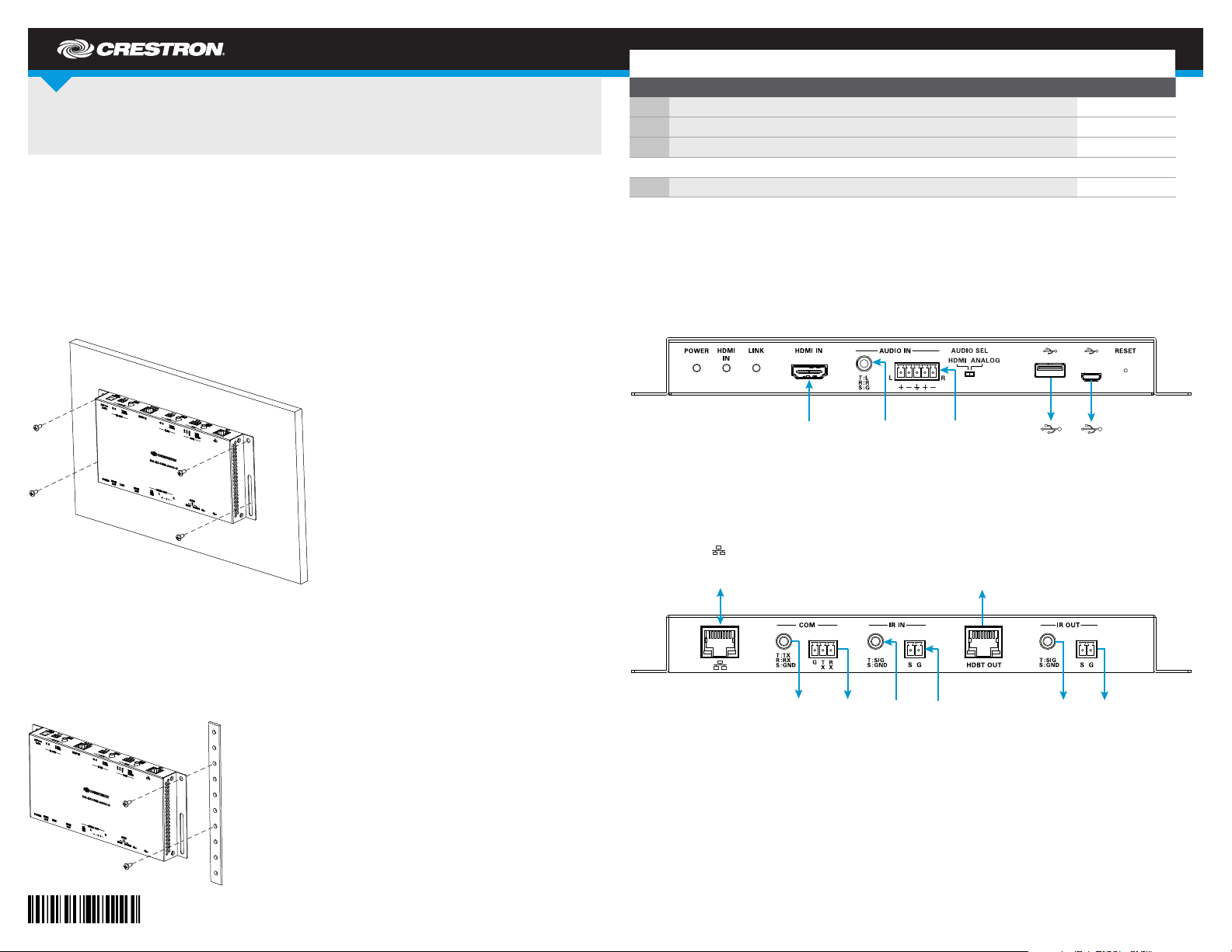
Connecting the Transmitter
Make connections to the front and rear panels of the transmitter.
Front Panel Connections
Mounting onto a Rack Rail
The transmitter and receiver can be mounted onto the front or rear rail of a rack. Position either the
left or the right mounting ange of the device so that the holes align with the holes in the rack. Then,
secure the device to the rack using two mounting screws (not included).
Mounting onto a Rack Rail
Rear Panel Connections
10BASE-T/100BASE-TX
Ethernet to LAN
HDMI IN:
From HDMI
audio/video
source
COM:
To
RS-232
device
AUDIO IN:
®
unbalanced
analog audio
COM:
To
RS-232
device
From
From IR
receiver
IR IN:
AUDIO IN:
From balanced/
unbalanced
analog audio
To HDBT IN port
of receiver
IR IN:
From IR
receiver
(Host):
To USB
device
IR OUT:
To IR
emitter
(Device):
To USB
host
IR OUT:
To IR
emitter
Page 2

Connecting the Receiver
24 V
device
host
Make connections to the front and rear panels of the receiver.
Front Panel Connections
Rear Panel Connections
HDMI OUT:
To HDMI
display
AUDIO OUT:
To analog audio
output device
AUDIO OUT:
AUDIO OUT:
To analog audio
To analog audio
output device
output device
(Host):
To USB
(Device):
To USB
DO Select the USB Data Transfer Mode
The front panel of the receiver provides a three-position USB switch. Set the switch to one of the
following positions:
• AUTO: (Default setting) Sets the USB mode to HOST or DEVICE based on the last device
connected to either of the two USB ports on the receiver. If the last connected device is
disconnected, the USB mode returns to the mode of the previously connected device.
• HO S T: Sets the USB mode to HOST, which allows data to pass between the USB Type A host
port on the receiver and the USB Type micro-B device port on the transmitter. Connection to the
USB Type micro-B device port on the receiver is ignored.
• DEVICE: Sets the USB mode to DEVICE, which allows data to pass between the USB
Type micro-B device port on the receiver and the USB Type A host port on the transmitter.
Connection to the USB Type A host port on the receiver is ignored.
NOTE: The USB mode of the transmitter is congured automatically to operate with the USB mode
of the receiver.
:
10BASE-T/100BASE-TX
Ethernet to LAN
COM:
To
RS-232
device
COM:
To
RS-232
device
IR IN:
From IR
receiver
HDBT IN:
From HDBT OUT
port of transmitter
IR IN:
From IR
receiver
IR OUT:
To IR
emitter
1.25 A:
From included
power pack
IR OUT:
To IR
emitter
NOTE: Connection of the included power pack to the receiver powers both the receiver and the
transmitter. Power is transmitted over the cable that connects the HDBT IN port of the receiver to the
HDBT OUT port of the transmitter.
As of the date of manu facture, the product h as bee n tested and foun d to comply with sp ecications for CE ma rking.
Federal Communications Commission (FCC) Compliance Statement
This device com plies w ith par t 15 of the FCC Rules. Operation is subject to the following two c onditions:
(1) This devic e may not cause harmful interference, and (2) this device must accept a ny inter fere nce received, including inte rference
that may cause undesired operation.
CAUTION: Changes or modication s not expressl y approved by the ma nufac turer responsible for comp lianc e could vo id the
user’s authority to operate the e quipment.
NOTE: This equipment has been te sted and found to c omply with the limits for a Class B digital device, pursu ant to part 15 of the
FCC Rules. Thes e limits are des igned to provide reaso nable p rotection aga inst harmful inter feren ce in a residential ins talla tion.
This equipment gene rates, uses an d can radiate radio frequency energ y and, if not installed and used i n accordance with the
instructions, may cause har mful in terferenc e to radio c ommun ications. However, there is no guarantee th at inter fere nce will not
occur in a particular installatio n.
DO Select the Audio Mode
The front panel of the transmitter provides a two-position audio selection switch. Set the switch to
one of the following positions:
• HDMI: (Default setting) Uses audio embedded in the HDMI stream.
• ANALOG: Inserts analog audio into the video stream.
DO Learn More
Visit the website for additional information and the latest rmware updates. To learn
more about this product, use a QR reader application on your mobile device to scan
the QR image.
Crestron Electronics
15 Volvo Drive, Rockleigh, NJ 07647
888.CRESTRON | www.crestron.com
If this equipment does c ause ha rmful inter feren ce to radio or telev ision r eception, which can b e determined by turning the
equipment of f and on, the user i s encouraged to try to correct the interference by one or more of the following m easures:
• Reorient or relocate the receiving antenna.
• Increase the separ ation b etween the equipment and receiver.
• Connect the e quipm ent into a n outle t on a circuit dif ferent from th at to whic h the rec eiver is conne cted.
• Consult the dealer o r an expe rienced radio/T V technician for help.
Industry Canada (IC) Compliance Statement
CAN ICES-3(B)/NMB-3(B).
The speci c patents that c over Crestron pro ducts are listed a t http://www.crestron.com/legal/patents. The produ ct warranty ca n be found at www.crestron.com/warranty.
Certa in Crestron pro ducts contain op en source soft ware. For speci c information, ple ase visit www.crestron.com/opensource.
Crestr on, the Crestro n logo, and Cresne t are either tradem arks or register ed trademarks of C restron Elec tronics, Inc. in t he United State s and/or other cou ntries. HDBa seT is either a tradema rk
or registe red trade mark of the H DBaseT Alliance in the U nited St ates and /or other co untries. HDMI is ei ther a trademark or reg istered t rademark o f HDMI Licensing L LC in the Uni ted Stat es
and/or ot her countries. O ther trademark s, registered tr ademarks, and tra de names may be used in thi s document to refer t o either the entit ies claiming the mark s and names or their pro ducts.
Crestr on disclaims any prop rietary inter est in the marks and na mes of others. Cre stron is not respo nsible for errors i n typography or ph otography.
This docum ent was written by t he Technical Publicat ions departmen t at Crestron.
©2017 Crestron Electronics, Inc.
DO GUIDE
DOC. 79 99A (2 04 9074) 06 .17
Specic ations subject to c hange without not ice.
 Loading...