

Page 1

North America Edition
Page 2

Page 3

Crestron Commercial Lighting Design Guide
Table of Contents
Introduction ........................................................................................................................................................ 1
Totally Integrated Building Control ................................................................................................................... 2
Specifying Crestron Lighting Systems .............................................................................................................. 3
Cresnet and Ethernet ........................................................................................................................................................................ 3
System Architecture ......................................................................................................................................................................... 3
Centralized Architecture ................................................................................................................................................................. 4
Distributed Architecture ................................................................................................................................................................. 5
Hybrid Architecture ........................................................................................................................................................................ 6
Product Families ............................................................................................................................................................................... 7
Common Applications .................................................................................................................................................................... 7
Written Specifications ...................................................................................................................................................................... 8
Green Light Designer Software ........................................................................................................................................................ 8
Lighting Systems ............................................................................................................................................... 9
Architectural Dimming ..................................................................................................................................................................... 9
When to Specify Architectural Dimming.......................................................................................................................................... 9
GLPD Panels ................................................................................................................................................................................ 11
GLPD-C Panels ............................................................................................................................................................................. 13
Module Specifications .................................................................................................................................................................. 15
Cabinets....................................................................................................................................................................................... 18
Power Switching............................................................................................................................................................................. 19
When to Specify Power Switching ................................................................................................................................................ 19
GLPS Panels................................................................................................................................................................................. 21
GLPS-C Panels ............................................................................................................................................................................. 23
Module Specifications .................................................................................................................................................................. 25
Cabinets....................................................................................................................................................................................... 28
Green Light Express ....................................................................................................................................................................... 29
GLPX Panels ................................................................................................................................................................................. 30
Module Specifications .................................................................................................................................................................. 31
DALI ................................................................................................................................................................................................. 35
When to Specify DALI Systems ..................................................................................................................................................... 35
Products ...................................................................................................................................................................................... 36
Room Solutions............................................................................................................................................................................... 39
When to Specify Room Solutions .................................................................................................................................................. 39
GLPAC-DIMFLV ............................................................................................................................................................................ 40
iLux .............................................................................................................................................................................................. 42
Cameo Dimmers and Switches..................................................................................................................................................... 45
Processors ....................................................................................................................................................... 48
PAC2 ................................................................................................................................................................................................ 48
PAC2M ............................................................................................................................................................................................. 49
IPAC-GL1 ......................................................................................................................................................................................... 50
DIN-AP2........................................................................................................................................................................................... 51
User Interfaces ................................................................................................................................................. 52
Wired Touchpanels ......................................................................................................................................................................... 52
Handheld Wireless Touchpanels .................................................................................................................................................... 54
Keypads .......................................................................................................................................................................................... 56
Cameo® ....................................................................................................................................................................................... 56
HTT-B10EX .................................................................................................................................................................................. 57
Decorator ..................................................................................................................................................................................... 58
i
Page 4

Crestron Commercial Lighting Design Guide
Designer ...................................................................................................................................................................................... 59
Mobile Interfaces ............................................................................................................................................................................ 60
Crestron Mobile Pro® ................................................................................................................................................................... 60
Crestron Mobile Pro G .................................................................................................................................................................. 60
XPanel & XPanel for Mac .............................................................................................................................................................. 60
Sensors............................................................................................................................................................. 61
The Sensor Advantage ................................................................................................................................................................. 61
Automated Actions ....................................................................................................................................................................... 61
Occupancy Products .................................................................................................................................................................... 61
Light Sensors ............................................................................................................................................................................... 62
Partition Products ......................................................................................................................................................................... 62
Sensor Interfaces ......................................................................................................................................................................... 62
Shades .............................................................................................................................................................. 63
How We Control ........................................................................................................................................................................... 63
How We Integrate ......................................................................................................................................................................... 63
Accessories ...................................................................................................................................................... 65
Viridian ............................................................................................................................................................. 70
Integrated Energy Management Software ..................................................................................................................................... 70
Sample Screen Shots ................................................................................................................................................................... 71
Appendix A - Touchpanel Graphics ................................................................................................................. 72
Appendix B - Common Keypad Layouts .......................................................................................................... 74
Appendix C - Glossary of Lighting Terms ....................................................................................................... 75
ii
Page 5

Crestron Commercial Lighting Design Guide
Introduction
This guide is designed to educate you on lighting system design using the wide
range of products found in the Crestron Green Light
is built on 40 years of expertise, vision, and innovation. From the very first
touchpanel to the first Ethernet-based control system, Crestron has defined
“integration.” Focused on bringing to market new and advanced solutions for
making life easier and greener, Crestron is continuing to engineer the future of
intelligent
Through our industry experience, we understand the value of scalability. We know
that the needs (and budgets) of today may be different tomorrow. Green Light
solutions are uniquely designed to grow over time while constantly providing a
reliable and consistent user experience. Solutions for the room can expand to fulfill
the needs of the entire building; a building may grow into a worldwide enterprise.
Crestron delivers solutions for venues and projects of all sizes.
building technology.
®
family. Crestron Green Light
Product scalability is crucial, but hardware is only as good as the software that
drives it. Crestron software tools are designed to integrate all areas of the system
to do anything you want them to do. Lights in a boardroom originally designed to
function locally can now hook into the room’s AV system for an integrated solution,
so when the source is switched to Blu-ray, the lights automatically dim. Similarly,
electric shades that were only intended to lower during AV presentations can now
be integrated to intelligently lower based on the angle of the sun and lumen level.
This data is shared with Crestron RoomView
global enterprise for energy tracking, monitoring, control and maintenance.
With Crestron, everything can be integrated and intelligently managed. This is the
power of Crestron: a solution that evolves with you. Welcome to Crestron—the only
solution solving the challenges of today and tomorrow.
®
Server Edition software across the
Introduction
1
Page 6

Crestron Commercial Lighting Design Guide
SSS
Totally Integrated Building Control
Imagine having total control over all building technology, across any number of locations, from a single easy to use interface. Only
Crestron makes it possible. With everything combined into one Crestron system, managing enterprise locations is easier than ever
before. With Viridian software, monitoring, tracking, and controlling resources is simply a click or touch away.
Modern commercial buildings are increasingly complex. Lighting, AV, HVAC, security, and other systems are all necessary in today’s
office. Crestron control processors easily interface with these systems. Lighting and AV systems are available directly from Crestron.
Other building technology, such as HVAC or security, is easily connected through a GLA-BMS or by directly connecting to a Crestron
control processor.
The graphic below depicts how Crestron can control a commercial building. Individual rooms have different solutions to their differing
needs, but all are connected via the Crestron control system. Blue circles represent pieces available directly from Crestron. White circles
are pieces provided by a third party (such as a television or light fixture).
CO2,
HUMIDITY &
TEMPERATURE
SENSORS
PARTITION
SENSORS
KEYPAD
OCCUPANCY
& PHOTOCELL
LIGHTS ON
LIGHTS OFF
SHADE
SHADE
SENSORS
S
T
CO2,
HUMIDITY &
TEMPERATURE
SENSORS
VAV / FCU
CONTROL
SHADES
+ - + - + - + -
DALI 1 DALI 2
TEST
CRESTRON
DIN-DALI-2
2-CHANNEL DALI INTERFACE
WITH BUS POWER SUPPLY
NET
24 Y Z G
CONTROLLER
INT EXT
DALI POWER
NET ID
OVERRIDE
OVR G OVR G
24 Y Z G
BALLASTS
DALI
DALI
VAV / FCU
COMPUTER
NET
OVR
PWR
SETUP
RESET
LAN PoE
CONTROL
SHADES
OCCUPANCY
& PHOTOCELL
SENSORS
POWER
SENSING
PUBLIC AREAS / OPEN OFFICE HOTEL ROOM / PATIENT ROOM
Power
POWER
SENSING
LIGHTING
CONTROLLER
CAUTION:RISKOF ELECTRICSHOCK- MORETHAN ONE
DISCONNECTSWITCHMAYBE REQUIREDTODE-ENERGIZE
THEEQUIPMENTBEFORESERVICING.
®
AVERTISSEMENT:CETÉQUIPEMENTRENFERME PLUSIEURS
CIRCUITSSOUSTENSION.VOIRLE SCHÉMA
PRECAUCION:PELIGRODEELECTROCUCION -SEREQUIERE
LADESACTIVACIONDE MASDEUN INTERRUPTORPARA
CORTARELSUMINISTRODEENERGIAELECTRICA ALEQUIPO
ANTESDEEFECTUARSERVICIO.
ENERGYMANAGEMENTFEATURES:
ALLCOVERMOUNTINGSCREWS MUSTBEINSTALLED AND
TIGHTENEDTOASSUREPROPERGROUNDING.
DIMMING
SWITCHING
NOUSERSERVICEABLEPARTSUNDERTHISCOVER.
SCHEDULING
LOADSHEDDING
CAUTION:SEEINSTRUCTIONMANUAL FORINSTALLATION,
OCCUPANCYSENSING
OPERATION,ANDMAINTENANCEINSTRUCTIONS.
DAYLIGHTHARVESTING
ENERGYUSAGEMONITORING
NETWORKMONITORINGANDCONTROL
CONTRIBUTESTOLEEDCERTIFICATION
MEETSASHRAE90.1REQUIREMENTS
MEETSCECTITLE24REQUIREMENTS
Totally Integrated Building Control
USGBCMEMBER
VAV / FCU
CONTROL
INDUSTRIAL
CONTROL
U
L
R
USC
EQUIPMENT
CO2,
HUMIDITY &
TEMPERATURE
SENSORS
OCCUPANCY
& PHOTOCELL
SENSORS
Switching
Cabinet
®
CRESTRON
LIGHTING
SHADES
KEYPAD
LIGHTS
LIGHTS
VOLUME
VOLUME
TEMP
TEMP
S
T
S
T
S
T
Lighting
Processor
CRESTRON
LIGHTING
LED
LIGHTING
OCCUPANCY
& PHOTOCELL
SENSORS
VENTILLATION
CO / CO2
SENSORS
LIGHTING
TOUCHPANEL
LIGHTING
PRESENTATION
SYSTEM
SHADES
PARTITION
SENSORS
AV RACK/
PROCESSOR
CONFERENCE ROOM / CLASSROOM
CO2,
HUMIDITY &
TEMPERATURE
SENSORS
OCCUPANCY
& PHOTOCELL
SENSORS
VAV / FCU
CONTROL
KEYPAD
LIGHTS
LIGHTS
VOLUME
VOLUME
TEMP
TEMP
PARKING / EXTERIOROFFICES
RoomView™
ENTERPRISE
SERVER
S
T
S
T
S
T
Metasys
MECHANICAL
BMS
PROCESSOR
SECURITY
SERVER
FIRE /
LIFE SAFETY
PROCESSOR
BUILDING MANAGEMENT
2
Page 7

Crestron Commercial Lighting Design Guide
Specifying Crestron Lighting Systems
This lighting design guide will help you choose the proper Crestron products for your application. A typical lighting system has at least a
lighting control module or cabinet, a processor, and a user interface. Follow these basic steps when navigating through this guide:
1. Survey all controlled lights and loads
Gather information on wattage, voltage, and fixture type. Specify each load as dimmed or switched, normal or emergency, and
central or local control.
2. Choose one or more lighting systems
Use the Product Families section to help you choose. Designate each load to a lighting system. Make sure not to exceed the
maximum load rating for each lighting system.
3. Choose one or more control processors
Use the Processors section. Room Solutions products can work without a processor, but may have limited expansion without
one.
4. Choose one or more user interfaces
5. Add in sensors, shades, and accessories for a more powerful system
Crestron’s Green Light Designer program can help with the design process. Currently, it supports Architectural Dimming, Power
Switching, and iLux systems. For more information see the Green Light Designer Software section.
For iLux
®
and wall box dimmers and switches, a separate user interface is not necessary, but recommended.
Specifying Crestron Lighting Systems
Cresnet and Ethernet
Throughout the design process, it is important to consider communication between devices. Almost every product in this guide is
capable of connecting via Cresnet. Cresnet is the communications backbone for Crestron systems. It is a simple, bi-directional network
combined with a 24 V power feed. Cresnet allows runs over several thousand feet, and the wiring topology is flexible. Unlike Ethernet,
and
there is no need for dozens of “home-run” cables – Cresnet can daisy-chain
When designing, try to avoid a large number of Cresnet devices on one circuit. There is a physical limit of 255 devices per segment, but
performance may limit you to far less devices. The acceptable number of Cresnet devices varies with usage and programming
complexity. Performance can be increased by using the Cresnet hubs described in the accessories section of this guide. The PAC2
processor includes several Cresnet segments built-in for high performance out of the box.
Cresnet supplies 24 V power to devices. Power is provided by select processors or a power supply. Insufficient or unstable power will
cause an unreliable system. To help you with the power calculations, a power calculator is available on the Crestron web site.
An Ethernet connection is available on some products, especially touchpanels and processors. Ethernet provides a high performance
connection. Power can be provided with devices that support POE (Power Over Ethernet).
home-run.
System Architecture
Crestron Green Light systems are available in a variety of configurations. Factors such as construction type, client requirements, and
architectural restrictions determine the best configuration. Lighting system architectures include centralized, distributed, and hybrid.
At the heart of each Green Light system is one or more control processors. This control system takes in user button presses or other
external events and turns them into single commands or even sequences of commands; dimming lights and closing shades can occur
with just one button press or occupancy sense. In addition to controlling lighting, fans, motors, HVAC, and security, the control system
can connect to building systems via Ethernet, RS-232, BACnet, LonWorks, and others.
3
Page 8

Crestron Commercial Lighting Design Guide
Centralized Architecture
Product Families: Architectural Dimming, Power Switching, Green Light Express
x High-voltage wiring home-runs from many rooms to a central Crestron panel
x Lights are controlled with keypads and touchpanels located anywhere
In a centralized system all the high-voltage lighting, motor, fan, and switch circuits draw power directly from modules in a Crestron
Green Light enclosure. Wired or wireless user interfaces can be placed throughout the building to control the various circuits. A
centralized design simplifies the high-voltage wiring through a “home-run” infrastructure in which each lighting circuit is connected
directly to the module within the Crestron enclosure.
The major benefit of a centralized architecture is the ability to program the user interfaces to control any load connected to the system.
This differs from traditional distributed infrastructure, whereby each circuit is controlled locally via the in-wall dimmer or switch.
Enabling load control through programming enables multi-point control as well as the ability to change how the system functions
through future updates. In addition to reducing wall clutter, multiple circuits can be controlled via a single button press, simply recalling
presets for different room configurations, events or atmospheres.
Centralized systems are appropriate for applications such as lobbies, hallways, parking garages, stadiums, and auditoriums.
Specifying Crestron Lighting Systems
Office 1 Office 2 Office 3 Office 4
Keypad
R R R
Touchpanel
R R R
Boardroom
Auditorium
M
Touchpanel
Wireless
Touchpanel
M
KEY
R
Troffer
Recessed
Track
Parking
M
Shade Motor
KeypadKeypadKeypad
Parking
Lot
GLPS
CABINET
R
R
120/277V
Control
4
Page 9

Crestron Commercial Lighting Design Guide
Distributed Architecture
Product Families: Room Solutions
x Wired in traditional configuration
x Each load is controlled by a local Crestron device
x In some cases, the local device has integrated keypad
x Keypad and touchpanel control are optional, allowing that load to be controlled from any location
In a distributed system, the high-voltage lighting, motor, fan, and switch circuits are wired in the traditional configuration with local
control. Controllable in-wall dimmers or switches replace the standard dimmers or switches and can be retrofitted into a project after
customary high-voltage wiring is completed. Crestron in-wall dimmers communicate with a control processor through either a Cresnet
(low-voltage control wire) or infiNET EX
power and flexibility of automation. In the event of a control system interruption, the user can still operate the lighting locally.
In the commercial space, in-wall solutions are appropriate for offices, small boardrooms, and hospitality. Typically in-wall dimmers or
switches support standard voltages (120/230VAC) and load types (incandescent, magnetic low-voltage). In the case where higher
voltages and loads are required, an expansion module can be added.
CLASSROOM 1 CLASSROOM 2
M
M
M
M
KEY
R
CLASSROOM 3
Troffer
Recessed
™
(mesh RF) wireless connection. This design combines the familiarity of local control with the
HTT-B10EX
GLPAC-
DIMFLV8-PM
Located in
Ceiling
HTT-B10EX
Keypad
Keypad
Keypad
Keypad
HTT-B10EX
GLPACDIMFLV8-PM
Located in
Ceiling
HTT-B10EX
M
M
M
M
CLASSROOM 4
Track
Parking
M
Shade Motor
120/277V
Control
Specifying Crestron Lighting Systems
5
Page 10

Crestron Commercial Lighting Design Guide
iL
Hybrid Architecture
Product Families: Mix centralized and distributed products.
x Combines both centralized and distributed architectures
x Offers complete building/enterprise control through flexible combinations of products
A hybrid system is a mix of both the centralized and distributed design. This allows local control where needed alongside sophisticated
central control for larger spaces. For example, a boardroom could have distributed local control while the lobby is on centralized control.
Hybrid designs typically achieve a good balance, delivering the control necessary at a reasonable budget. In many commercial spaces,
mechanical/electrical room space is limited (this is where the Green Light enclosures must be installed). By using a logical mix of
centralized and distributed control, entire buildings can be connected to a control network that offers total control, monitoring and
management.
Office 1 Office 2 Office 3 Office 4
KeypadKeypad
Keypad
Keypad
Parking
Lot
R R R
iLux
R R R
Boardroom
Cameo
Auditorium
iLux
Specifying Crestron Lighting Systems
M
Wireless
Touchpanel
M
ux
GLPS
CABINET
R
CAEN
CABINET
With
PAC2
R
Dimmer
KEY
Troffer
R
Recessed
Track
Parking
M
6
Shade Motor
120/277V
Control
Page 11

Crestron Commercial Lighting Design Guide
Product Families
Crestron has developed a number of Green Light products to suit the broad range of applications in the world of commercial lighting.
Architectural Dimming: Centralized dimming and switching, 16A per circuit, and support for a wide range of loads.
x
Built-in, pre-wired circuit breakers are optional.
x
Power Switching: Centralized switching, 16A per circuit, and support for 0-10V dimming. All models include pre-
wired circuit breakers.
x
Green Light Express: Centralized dimming and switching requiring a separate circuit breaker panel, up to 16A per
circuit, and support for a wide range of loads. Because there are no breakers, the cabinet is more compact.
x
DALI: Digitally addressable dimming and switching using the DALI open standard. DALI commissioning tool simplifies
deployment. Ballasts are wired directly to circuit breakers, and digital control information is sent to ballasts. DALI mounts
in a standard DIN Rail cabinet alongside other Crestron and third-party DIN Rail products.
Room Solutions: Distributed lighting and shade control designed for local installation. Used for a single room or small
x
group of rooms. Some products come with infiNET EX
Common Applications
The table below represents the different Crestron product families. Common usage scenarios are listed at left. Dots show a typical
solution for each scenario.
Key: 9 - Acceptable Solution
Arch. Dimming Power Switching Green Light Express Room Solutions DALI
Auditorium
Cafeteria
Classroom
Office Space
Parking Lot
Restaurant
Stadium
9 9 9 9
9 9 9
9 9 9 9
Centralized Architecture Distributed Architecture Addressable Lighting
9 9 9
9 9
9 9
9 9
TM
for reliable wireless communication and easy retrofitting.
9
9
Specifying Crestron Lighting Systems
7
Page 12

Crestron Commercial Lighting Design Guide
Written Specifications
Comprehensive Section 26 specifications are available for download on the Crestron website. These specifications can be implemented
within lighting project specifications to ensure bids meet the appropriate requirements as set by Crestron.
Specifications are located at www.crestron.com/greenlightspecs
Green Light Designer Software
Crestron Green Light Designer allows you to design and document a complete, energy-efficient commercial lighting solution that
combines facility-wide lighting, shade/drape control with audio/video integration and network management - all without requiring
extensive knowledge of Crestron products, or any other Crestron software.
Green Light Designer features a straightforward user interface, with all data entry confined to four easy-to-use tabs: load schedule,
shades, control stations, and sensors. As you define your project, an equipment list of required Crestron products is generated
automatically behind the scenes.
Once the project is designed and configured, Green Light Designer allows you to generate attractive and easy to read reports such as
one-line diagrams, load schedules, shade schedules, equipment lists, and equipment lists by room. Reports can be generated in a
variety of formats (e.g. PDF, Excel, HTML, CSV, text) ready to be sent via email or imported into other applications.
Green Light Designer Screenshot
Specifying Crestron Lighting Systems
8
Page 13

Crestron Commercial Lighting Design Guide
Lighting Systems
Architectural Dimming
Crestron Green Light Architectural Dimming products are designed for control of lighting in theaters, restaurants, offices, and anywhere
centralized dimming is desired. With a range of panel sizes and configurations available, every system is fully scalable to custom fit
each installation. An extensive selection of Crestron keypads, touchpanels, occupancy sensors, photocells, shade controllers, and
numerous other peripheral options afford astounding design flexibility with unparalleled capability for integration.
x Centralized dimming system
x Available with integrated main lug and branch breakers
x Keypads and touchpanels offer flexible control anywhere
x Astronomical clock allows events to be scheduled around sunrise/sunset
x Sensor integration for occupancy sensing and daylight harvesting
x Emergency override assures reliable lighting in critical areas
GLPD panels are available with integrated circuit breakers. GLPD panels without integrated circuit breakers are known as “feed-thru”
cabinets. Dimming in a feed-thru cabinet is also available with the GLPX panel from the Green Light Express product line. To learn more
or configure a GLPX panel, see the Green Light Express section on page 29.
When to Specify Architectural Dimming
If you need to dim a large amount of lighting loads, Architectural Dimming panels are the tools for the job. When specifying, keep in
mind that the panel requires all load wiring to home-run to a single location, preferably a utility room where the panel can be installed. A
single panel can control up to 60 lighting loads. If necessary, multiple panels can be configured and connected through the control
system. With Architectural Dimming panels, no job is too big.
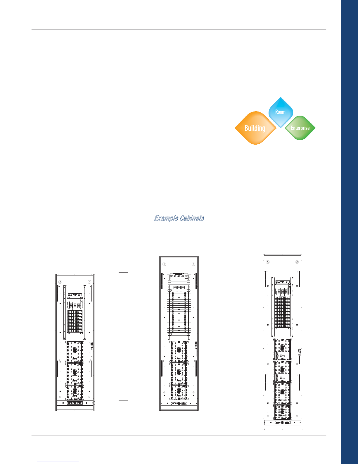
Example Cabinets
GLPD 2x2 Cabinet
(4) DIM6 Modules
120 Volt Breakers, MLO
Wiring, Front Cover Not Shown
GLPD 3x4 Cabinet
(10) DIM6 Modules
277 Volt Breakers, MLO
Wiring, Front Cover Not Shown
GLPD 3x2-FT Cabinet
(2) DIM6, (2) HSW8, (2) DIMFLV8
Feed-Thru
Wiring, Front Cover Not Shown
Architectural Dimming
Breakers
Lighting
Modules
9
Page 14
Crestron Commercial Lighting Design Guide
Example Architectural Dimming Application
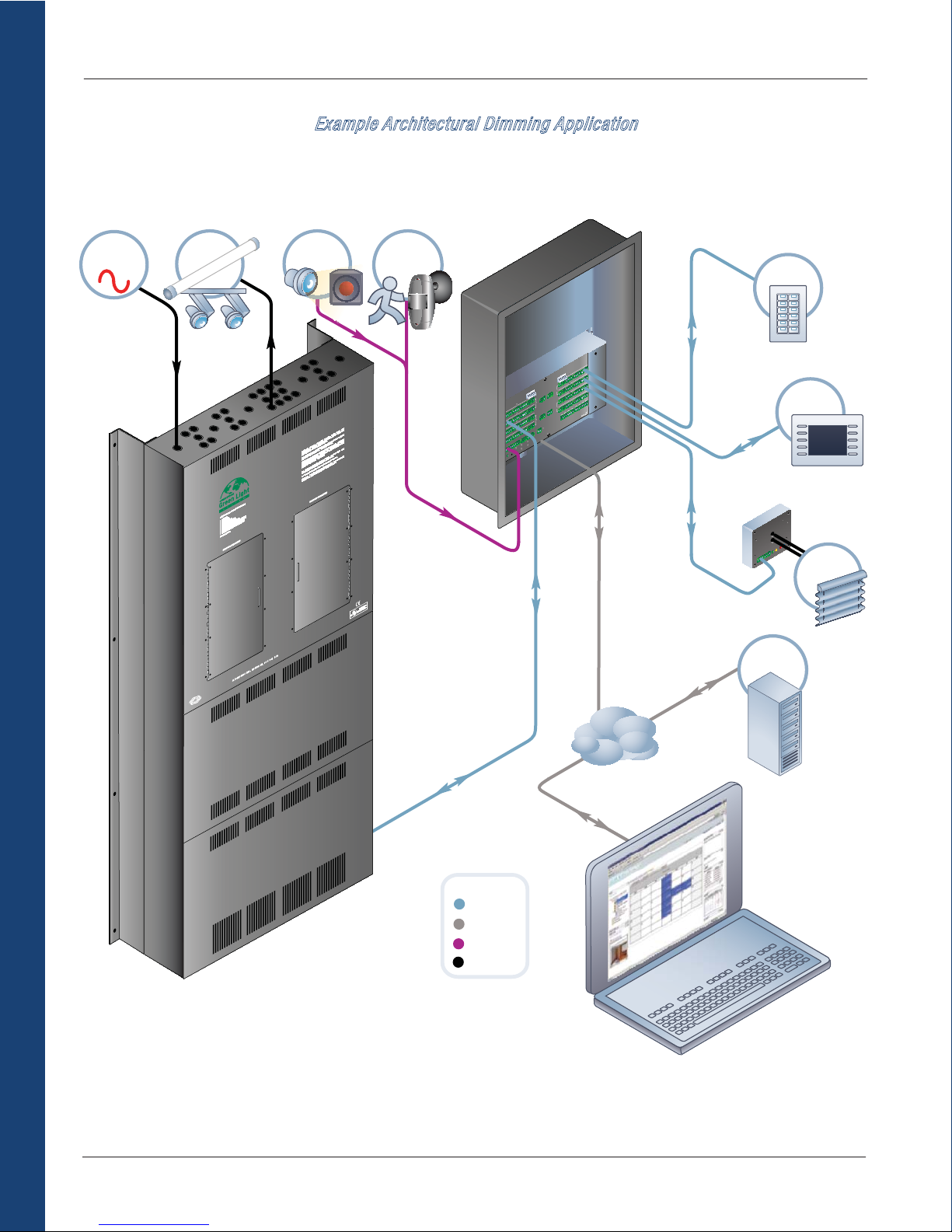
Below is an example Architectural Dimming panel application. AC wiring from the panel powers and controls the lighting fixtures
directly. The panel connects to a PAC2 processor via Cresnet. Also connected to the PAC2 are shade controllers, a photocell, a motion
sensor, a keypad, and a touchpanel. Everything can be controlled and monitored from the connected PC by using RoomView
TM
.
ELECTRIC
LIGHTING
UTILITY
AC
CRESTRON
Architectural Dimming
AC
®
PHOTOCELL
MOTION
SENSOR
CONTROL
PAC2
Z G
4Y
2
A
Z G
T
NE
24Y
Z G
Z
Y
Y
4
2
24
Z G
Y Z G
NET B
24Y
24
Z G
Z G
Y
Y
4
24
2
Z G
Z G
Y
Y
NET E
24
24
Z G
Z G
Y
Y
24
24
Z G
Z G
Y
Y
P
NET F
U
4
K
2
24
C
A
B
NPUT
I
ET
Z G
Z G
N
Y
Y
R
VE
24
24
O
E
D
RI
R
L
Z G
Y
G
24
G
8
O
/
7
I
—
6
5
LNK
—
3 4
S4
2
1
ACT—
LAN B
—
NET
NA
LA
R
-
HW
ERR
PWR
R
-
SW
KEYPAD
G
Z
Y
24
G
C
Z
Y
NET
24
G
G
Z
Z
Y
Y
ER
T
24
U
24
MP
G
G
CO
D
N
Z
Z
Y
IO
Y
ET
IGHT
N
R
AT
4
24
2
M
TO
G
G
AU
L
Z
Z
A
Y
Y
N
O
24
SI
24
ES
F
O
R
G
P
Z G
R
Z G
Y
Y
2
NET
4
4
T
2
2
EXT
POWE
N
I
LEFT
G
Z G
Z G
1
Y
Y
24
24
EXT
NT
I
G
H
G
Z
Z G
Y
NET
4Y
24
2
8
7
Z G
Y
6
24
UTPUT
5
G
O
Z
Y
G
Y
4
4
RELA
24
T
EXT
POWER
N
I
3
G
3
2
T
EXT
N
I
1
5
S
G
T
AUL
F
G
F
—
TOUCH
PANEL
CRESNET
Shade Controller
LAN
C2N-SDC
-
SETUP
-
NET
T
E
N
PWR
G
Z
USA
Y
7
24
. 0764
T
J
G
E
N
N.
.
C
Y Z
4
N
2
I
S
C
CTRONI
ON ELE
R
T
ES
CR
SHADES
RoomView
SERVER
LAN
LAN
ARCHITECTURAL
DIMMING PANEL
CRESNET
LAN
Color Key
Cresnet
LAN
Control
AC
TM
RoomView
10
Page 15

Crestron Commercial Lighting Design Guide
GLPD Panels
Crestron GLPD Architectural Dimming panels can dim a wide range of lighting types. There are many configurations available for any
budget or need. This text describes how to design your panel configuration and how to name it for ordering.
GLPD Panel Naming System
GLPD
When ordering an architectural dimming panel, construct a model name as shown above. Possible choices are listed underneath each
blue box. The numbered steps below describe each part of the name in detail.
Examples: GLPD-DIM-MCB80-24-120-10K
GLPD-DIM-FT-36
1. Module Type GLPD-DIM-___-___-___-___
GLPD panels are only available with DIM modules. If you want to mix dimming, switching and 0-10V lighting control into a single
cabinet, see the GLPD-C product on page 13. The GLPD-C panel is a custom panel with three possible module types.
Key: { - Switchable
z - Dimmable
2 and 3-wire fluorescent
MLV/ELV
Incandescent
Neon/cold cathode
Standard LED
0-10V LED
Load Types
0-10V fluorescent
HID and Motor
Voltage 100 to 277 Volts
Additional Module Info Page 15
2. Feed Type GLPD-DIM-___-___-___-___
MLO Main Lug Only with 20A branch breakers
MCB60 60A back-fed main circuit breaker with 20A branch breakers
MCB80 80A back-fed main circuit breaker with 20A branch breakers
MCB100 100A back-fed main circuit breaker with 20A branch breakers
MCB125 125A back-fed main circuit breaker with 20A branch breakers
FT Feed-thru with no integrated branch breakers
-
Module
Type
DIM
Feed Type
----
MLO
MCB60
MCB80
MCB100
MCB125
FT
Module
DIM
z
z
z
z
z
{
{
{
Number of
Loads
1
2
3
...
58
59
60
120
277
AIC RatingVoltage
10K
18K
22K
35K
65K
Architectural Dimming
11
Page 16

3. Number of Loads GLPD-DIM-___-___-___-___
Find the row in the table that matches your choices in steps 1 and 2. The numbers in blue represent the maximum number of loads for
each cabinet size. You can choose any number up to the maximums listed below. See page 18 for more information on the cabinet
sizes.
DIM-MLO 24 36 48 60 - -
DIM-MCB 24 36 48 57* - -
Loads
DIM-FT - - - - 24 36
Maximum # of
*If using 120/208V and 125A MCB, reduce the maximum number of loads shown by three.
Note: For feed-thru cabinets only (-FT), the model name is complete after step three. Skip steps four and five.
4. Voltage GLPD-DIM-___-___-___-___
To specify the circuit breaker voltage, enter “120” for 120/208V or “277” for 277/480V.
5. AIC Rating GLPD-DIM-___-___-___-___
Choose one of the following values from the appropriate column to specify the Ampere Interrupting Capacity of the circuit breakers.
Architectural Dimming
When a short circuit occurs, a large amount of current flows into the circuit breaker and it trips. The
Ampere Interrupt Capacity rating is the maximum current the breaker can safely interrupt. If the short
circuit current exceeds the AIC rating of the breaker, the circuit breaker may fail. For safe operation,
the AIC rating must exceed the available fault current at the panel.
Crestron Commercial Lighting Design Guide
Cabinet Sizes
2x2 3x2 2x4 3x4 2x2-FT 3x2-FT
120 Volt 277 Volt
10K 18K
22K 35K
65K 65K
What is AIC?
12
Page 17

Crestron Commercial Lighting Design Guide
GLPD-C Panels
For architectural dimming panels with mixed module types, a “C” is attached to the model name (denoting custom). The number of
each module type is specified within the product name.
GLPD-C Panel Naming System
GLPD-C
-
# of DIM
Modules
1DIM
2DIM
3DIM
4DIM
5DIM
6DIM
7DIM
8DIM
9DIM
# of FLV
--- -
Modules
1FLV
2FLV
3FLV
4FLV
5FLV
6FLV
7FLV
# of HSW
Modules
1HSW
2HSW
3HSW
4HSW
5HSW
6HSW
7HSW
Feed Type
MLO
MCB60
MCB80
MCB100
MCB125
FT
Voltage AIC Rating
-
120
277
10K
18K
22K
35K
65K
When ordering an architectural dimming panel, construct a model name as shown above. Possible choices are listed underneath each
blue or gray box. The gray boxes represent the modules and may be eliminated from the model name if not used. The numbered steps
below describe each part of the model name in detail.
Examples: GLPD-C-2DIM-2FLV-FT
GLPD-C-2FLV-4HSW-MCB100-120-65k
1. Feed Type GLPD-C-___-___-___-___-___-___
MLO Main Lug Only with 20A branch breakers
MCB60 60A back-fed main circuit breaker with 20A branch breakers
MCB80 80A back-fed main circuit breaker with 20A branch breakers
MCB100 100A back-fed main circuit breaker with 20A branch breakers
MCB125 125A back-fed main circuit breaker with 20A branch breakers
FT Feed-thru with no integrated branch breakers
2. Number of DIM, FLV, and HSW GLPD-C-___-___-___-___-___-___
In the table below are the possible module choices. To design the cabinet, select quantities of these three modules. A DIM module wires
6 loads, an FLV module wires 8 loads, and an HSW module wires 8 loads. Therefore the total number of loads will be:
(# of DIM modules × 6) + (# of FLV modules × 8) + (# of HSW modules × 8)
See the next page for an example calculation.
Key: { - Switchable
z - Dimmable
2 and 3-wire fluorescent
MLV/ELV
Incandescent
Neon/cold cathode
Standard LED
Load Types
0-10V LED
0-10V fluorescent
HID and Motor
DIM (6 Loads) FLV (8 Loads) HSW (8 Loads)
z { {
z { {
z { {
z { {
z { {
{ z {
{ z {
{ { {
Modules
Voltage 100 to 277 Volts 100 to 277 Volts 100 to 277 Volts
Additional Module Info Page 15 Page 16 Page 17
Architectural Dimming
13
Page 18

Crestron Commercial Lighting Design Guide
Find the row in the table below that matches your choice in step 1. In that row is the maximum number of loads for each cabinet size.
Choose a cabinet size, and do not exceed the maximums when designing the panel. See page 18 for more information on the cabinet
sizes.
Max # of Modules 4 6 8 12 4 6
MLO 30 42 60 60 - -
MCB 27* 39* 57* 57* - -
Loads
Max # of
FT - - - - 32 48
* If using 120/208V and MCB125, reduce the maximum number of loads shown by three.
Now choose quantities of DIM, FLV, and HSW modules, but do not exceed the maximum number of modules and maximum number of
loads determined from the table above.
As an example, say you have 4 DIM loads, 20 FLV loads, and 15 HSW loads. This would require 1 DIM module, 3 FLV modules, and 2
HSW modules = 6 modules. Using the formula on the previous page, these six modules wire a total of 46 loads.
The cabinet size will be 2x4 because it is the smallest cabinet that can accommodate 6 modules and 46 circuits.
2x2 3x2 2x4 3x4 2x2-FT 3x2-FT
(1 × 6) + (3 × 8) + (2 × 8) = 46 loads
Cabinet Size
Note: It is possible to wire in fractions of modules when there are not enough breakers available for the modules you want. In this
circumstance please call Crestron Sales Support Services.
Note: For feed-thru cabinets only (-FT), the model name is complete after step two. Skip steps three and four.
3. Voltage GLPD-C-___-___-___-___-___-___
Architectural Dimming
To specify the circuit breaker voltage, enter “120” for 120/208V or “277” for 277/480V.
4. AIC Rating GLPD-C-___-___-___-___-___-___
Choose one of the following values from the appropriate column to specify the Ampere Interrupting Capacity of the circuit breakers.
When a short circuit occurs, a large amount of current flows into the circuit breaker and it trips. The
Ampere Interrupt Capacity rating is the maximum current the breaker can safely interrupt. If the short
circuit current exceeds the AIC rating of the breaker, the circuit breaker may fail. For safe operation,
the AIC rating must exceed the available fault current at the panel.
120 Volt 277 Volt
10K 18K
22K 35K
65K 65K
What is AIC?
14
Page 19

Crestron Commercial Lighting Design Guide
Module Specifications
GLX-DIM6
The GLX-DIM6 is a Crestron Green Light architectural dimming module which
features 6 channels of incandescent, magnetic low-voltage, and 2- and 3wire fluorescent dimming. The module is part of a complete Crestron
engineered GLPD Green Light architectural dimming panel.
> 6 channels of incandescent, MLV, 2- & 3-wire fluorescent dimming
> Phase-synchronous detection eliminates lamp flicker
> Selectable non-dim mode
> Supports 100 to 277 Volt applications
> 16 Amp load rating per channel
> Short circuit and overload protection
> Positive air gap at each output
> Phase-independent channels
> Cresnet communications
> Redundant power capability—module powered via line or Cresnet
> Local controls for testing and verification
> Local and remote override capability
> Non-volatile power failure memory
Load Ratings
Switch Channels 6
Per Channel 16 Amps at 100-277 Volts AC, 50/60 Hz
Dim Load Types
Switch Load Types Incandescent, Magnetic Low-Voltage, Electronic Low-Voltage, Neon/Cold Cathode, Fluorescent
Power Requirements
Primary 100-277 Volts AC, 50/60Hz, supplied via channel 1 (L1, N1)
Secondary (optional) 9 watts at 24 Volts DC, supplied via Cresnet®
Environmental
Temperature 32° to 104°F (0° to 40°C)
Humidity 10% to 90% RH (non-condensing)
Heat Dissipation 550 BTU/Hr
Electrical Regulatory Certifications
UL508, Section 41 (Endurance Test) and Section 61C (Electronic Ballasts)
UL924, Emergency Power Equipment
IEC60669-2-1, Section 19.102 (Contact mechanisms incorporated in electronic switches, intended for fluorescent lamp circuits or
other capacitive loads)
Module SCCR Rating - 65kA
CE
Incandescent, Magnetic Low-Voltage, Neon/Cold Cathode, 2-wire Fluorescent Ballast, or 3-wire
Fluorescent Ballast
Ballast, High-Intensity Discharge
Architectural Dimming
15
Page 20

GLX-DIMFLV8
The GLX-DIMFLV8 is a Crestron Green Light architectural dimming module
which features 8 channels of 4-wire, 0-10 Volt fluorescent dimming. The
module is part of a complete Crestron engineered GLPD Green Light dimming
panel.
> 8 channels of 4-wire 0-10 Volt fluorescent dimming
> Compatible with lighting and motor loads
> Supports 100 to 277 Volt applications
> 16 Amp load rating per channel
> Arcless switching
> Positive air gap at each output
> Phase-independent channels
> Cresnet communications
> Redundant power capability—module powered via line or Cresnet
> Local controls for testing and verification
> Local and remote override capability
> Non-volatile power failure memory
Architectural Dimming
Load Ratings
Dimmer Channels 8
Per Channel 16 Amps at 100-277 Volts AC, 50/60 Hz
Dim Load Types 0-10 Volt fluorescent ballast (4-wire); 60 mA max current sink
Switch Load Types Incandescent, Magnetic Low-Voltage, Electronic Low-Voltage, Neon/Cold Cathode, Fluorescent
Relay Lifetime 1,000,000 on/off operations at full electronic ballast load
Power Requirements
Primary 100-277 Volts AC, 50/60Hz, supplied via channel 1 (L1, N1)
Secondary (optional) 5 watts at 24 Volts DC, supplied via Cresnet®
Environmental
Temperature 32° to 104°F (0° to 40°C)
Humidity 10% to 90% RH (non-condensing)
Heat Dissipation 116 BTU/Hr
Electrical Regulatory Certifications
UL508, Section 41 (Endurance Test) and Section 61C (Electronic Ballasts)
UL924, Emergency Power Equipment
IEC60669-2-1, Section 19.102 (Contact mechanisms incorporated in electronic switches, intended for fluorescent lamp circuits or
other capacitive loads)
Module SCCR Rating - 65kA
CE
Crestron Commercial Lighting Design Guide
0.5 HP @ 120 Volts, 1 HP @ 230 Volts, 1 HP @ 277 Volts
Ballast, High-Intensity Discharge, Motor
16
Page 21

Crestron Commercial Lighting Design Guide
GLX-HSW8
The GLX-HSW8 is a Crestron Green Light architectural dimming module which
features 8 channels of high inrush switching. The module is part of a
complete Crestron engineered GLPD Green Light dimming panel.
> 8 channels of high inrush switching
> Compatible with lighting and motor loads
> Supports 100 to 277 Volt applications
> 16 Amp load rating per channel
> Arcless switching
> Positive air gap at each output
> Phase-independent channels
> Cresnet communications
> Redundant power capability—module powered via line or Cresnet
> Local controls for testing and verification
> Local and remote override capability
> Non-volatile power failure memory
Load Ratings
Dimmer Channels 8
Per Channel 16 Amps at 100-277 Volts AC, 50/60 Hz
0.5 HP @ 120 Volts, 1 HP @ 230 Volts, 1 HP @ 277 Volts
Dim Load Types 0-10 Volt fluorescent ballast (4-wire); 60 mA max current sink
Switch Load Types Incandescent, Magnetic Low-Voltage, Electronic Low-Voltage, Neon/Cold Cathode, Fluorescent
Ballast, High-Intensity Discharge, Motor
Relay Lifetime 1,000,000 on/off operations at full electronic ballast load
Power Requirements
Primary 100-277 Volts AC, 50/60Hz, supplied via channel 1 (L1, N1)
Secondary (optional) 5 watts at 24 Volts DC, supplied via Cresnet®
Environmental
Temperature 32° to 104°F (0° to 40°C)
Humidity 10% to 90% RH (non-condensing)
Heat Dissipation 112 BTU/Hr
Electrical Regulatory Certifications
UL508, Section 41 (Endurance Test) and Section 61C (Electronic Ballasts)
UL924, Emergency Power Equipment
IEC60669-2-1, Section 19.102 (Contact mechanisms incorporated in electronic switches, intended for fluorescent lamp circuits or
other capacitive loads)
Module SCCR Rating - 65kA
CE
Architectural Dimming
17
Page 22

Crestron Commercial Lighting Design Guide
Cabinets
Regular cabinets have built-in circuit breakers. The cabinets are shipped with wiring from the breakers to the modules completed for
easy installation. Feed-thru cabinets require a separate breaker panel next to the GLPD panel.
Cabinet Sizes 2x2 3x2 2x4 3x4
Height
Width
Depth
67.8 in
(172.3 cm)
22.8 in
(58.1 cm)
10.6 in
(27 cm)
96.0 in
(243.8 cm)
22.8 in
(58.1 cm)
10.6 in
(27 cm)
67.8 in
(172.3 cm)
35.1 in
(89.1 cm)
10.6 in
(27 cm)
89.9 in
(228.1 cm)
35.1 in
(89.1 cm)
10.6 in
(27 cm)
Module Layout
Architectural Dimming
Cabinet Sizes 2x2-FT 3x2-FT
Height
Width
Depth
35.9 in
(91.1 cm)
22.8 in
(58.2 cm)
10.2 in
(25.9 cm)
54.8 in
(139.1 cm)
22.8 in
(58.2 cm)
10.2 in
(25.9 cm)
Layout
18
Page 23
Crestron Commercial Lighting Design Guide
Power Switching
Crestron Green Light Power Switching products are designed for control of lighting in office buildings, warehouses, parking garages,
sports facilities, public spaces, and anywhere centralized switching is required. With a range of panel sizes and configurations available,
every system is fully scalable to custom fit each installation. An extensive selection of Crestron keypads, touchpanels, occupancy
sensors, photocells, shade controllers, and numerous other peripheral options afford astounding design flexibility with unparalleled
capability for integration.
x Centralized switching system with integrated main lug and branch breakers
x Keypads and touchpanels offer flexible control anywhere
x Astronomical clock allows events to be scheduled around sunrise/sunset
x Sensor integration for occupancy sensing and daylight harvesting
x Emergency override assures reliable lighting in critical areas
GLPS panels come with integrated circuit breakers. Power switching without integrated circuit breakers is available in the GLPX panel
from the Green Light Express product line. To learn more or configure a GLPX panel, see the Green Light Express section on page 29.
When to Specify Power Switching
If you need load switching and have a large amount of lighting circuits, Power Switching panels are the tools for the job. When
specifying, keep in mind that the panel requires all lighting wiring to run to a single location, preferably a utility room where the panel
can be installed. A single panel can control up to 42 lighting circuits. If necessary, configure multiple panels and easily connect them
using Crestron’s control system. With Power Switching panels, no job is too big.
Example Cabinets
GLPS Medium Cabinet
(2) HSW12, (1) HSW8
120 Volt Breakers, MLO
Wiring, Front Cover Not Shown
GLPS Large Cabinet
(2) SW16, (1) SW10
277 Volt Breakers, MLO
Wiring, Front Cover Not Shown
GLPS Extra Large Cabinet
(2) FLV8, (1) SW16, (1) SW10
120 Volt Breakers, MLO
Wiring, Front Cover Not Shown
Power Switching
Breakers
Switching
Modules
19
Page 24

Crestron Commercial Lighting Design Guide
Example Power Switching Application
Below is an example power switching application with backup power operation using a GLS-PLS phase loss sensor (see accessories
section for more details). The power switching panels connect to an IPAC-GL1 processor via Cresnet. Connected to the processor are
various sensors, a keypad, and a photocell. It is possible to add up to two touchpanels to the IPAC-GL1 as well. Connected via a LAN is a
PC running RoomView. A GLA-PWS50 provides power to the processor.
CRITICAL
LIGHTING
EMERGENCY
TRANSFER
Normal/Emergency Feed
SWITCH
AC
ELECTRIC
UTILITY
LIGHTING
Emergency Feed
Normal Feed
AC
CRESTRON
®
TRONICS
EC
EL
Normal Feed
U
L
A
US
07647
J
EIGH, N
KL
C
O
NC. R
I
Override
®
Sensor
GLS-PLS-120/277
Loss
Power
Emergency Lighting Interface
C
PHASE
B
A
AL
M
NOR
TEST
N
CRESTRO
GLS-PLS120/277
Phase
Loss
Sensor
®
EIGH,
CKL
O
NC. R
I
ICS
N
ECTRO
EL
ESTRON
CR
GENERATOR
NON-CRITICAL
Power Switching
KEYPAD
M
F
CD
DSS
CD 2
AUX
APE
T
E
MUT
ON/OFF
VOL
-
VOL
CRESTRON
OCCUPANCY
GLS-SIM
ESTRO
CR
POWER
NET
GLS-
NET
4 Y Z G
2
SENSOR
LO
C
HI
N
C
SETUP
M
R
SI
SENSO
G
2
4 1
2
PHOTOCELL
CRESTRON
SENSOR
24VDC
CRESNET
U
L
USA
07647
NJ
RoomView
ON
TR
CRES
IPAC-GL1
LAN
SERVER
LAN
LAN
Color Key
Control
Cresnet
LAN
AC
24VDC
GLPS Power
Switching Panel
GLPS Power
Switching Panel
120 to 230VDC
20
24VDC
GLA-PWS50
Power Supply
LAN
TM
RoomView
Page 25

Crestron Commercial Lighting Design Guide
GLPS Panels
Crestron GLPS Series power switching panels feature field-replaceable switching modules with a choice of relay technologies to
address a wide range of applications and budgets. In addition to switching, some Green Light Power Switching panels also allow the
option to add dimming control for 0-10V fluorescent ballasts and 0-10V LEDs. Switching relays are available in arcless or standard form.
Arcless relays provide increased durability for a higher rated lifetime over standard relays.
GLPS Panel Naming System
GLPS
When ordering a power switching panel, construct a model name as shown above. Possible choices are listed underneath each blue
box. The numbered steps below describe each choice in detail.
Example: GLPS-HSW-MLO-30-120-10
1. Relay Type GLPS-___-___-___-___-___-___
Determine the type of switching relay required. Use the following table to determine the appropriate relay. If you wish to mix relay types
within a panel, see the GLPS-C panel on page 23.
Switching Relay Types High-inrush Arcless high-inrush Arcless high-inrush
Voltages 120/230/277 120/230/277 120/230/277
Lighting Output Capacity 16A 16A 16A
Motor Output Capacity
(120/230/277 V)
Rated Relay Lifetime Up to 100,000 1,000,000 1,000,000
0-10V Dimming No No Yes
Additional Relay Info Page 25 Page 26 Page 27
Crestron offers two switching relay types: high-inrush and arcless high-inrush. Arcless high-inrush relays use a TRIAC to handle the
current turn on. Within milliseconds, the continuous load is transferred from the TRIAC to a robust 50A mechanically-latching relay.
All switching occurs at the zero-cross point of the AC waveform under microprocessor control. This is a complete solution
eliminating arcing at the physical relay contacts during turn on and turn off. By eliminating arcing, the relay lifetime is increased
substantially.
2. Feed Type GLPS-___-___-___-___-___-___
MLO Main Lug Only with 20A branch breakers
MCB60 60A back-fed main circuit breaker with 20A branch breakers
MCB80 80A back-fed main circuit breaker with 20A branch breakers
MCB100 100A back-fed main circuit breaker with 20A branch breakers
MCB125 125A back-fed main circuit breaker with 20A branch breakers
Relay Type
--
SW
HSW
FLV
Feed Type
-
MLO
MCB60
MCB80
MCB100
MCB125
SW HSW FLV
1/2/2 hp 0.5/1/1 hp 0.5/1/1 hp
What is Arcless Switching?
Number of
Loads
1
2
3
...
40
41
42
-
Voltage
120
277
Relays
AIC Rating
-
10K
18K
22K
35K
65K
Door
-
Option
ND
Power Switching
21
Page 26

3. Number of Loads GLPS-___-___-___-___-___-___
Find the row in the table that matches your choices in steps 1 and 2. The numbers in blue represent the maximum number of loads for
each cabinet size. Choose a cabinet size, and do not exceed the maximums when designing the panel. See page 28 for more
information on the cabinet sizes.
HSW-MLO 30 32 42
HSW-MCB 27* 32 39*
SW-MLO 30 42 -
of Loads
Maximum #
SW-MCB 27* 39* -
*If using 120/208V and 125A MCB, reduce the maximum number of loads shown by three.
4. Voltage GLPS-___-___-___-___-___-___
To specify the circuit breaker voltage, enter “120” for 120/208V or “277” for 277/480V.
5. AIC Rating GLPS-___-___-___-___-___-___
Choose one of the following values from the appropriate column to specify the Ampere Interrupting Capacity of the circuit breakers.
Power Switching
6. Door Option GLPS-___-___-___-___-___-___
Enter “ND” to omit the local control access door. Otherwise truncate this from the model name.
Crestron Commercial Lighting Design Guide
Cabinet Size
Medium Large Extra Large
120 Volt 277 Volt
10K 18K
22K 35K
65K 65K
What is AIC?
When a short circuit occurs, a large amount of current flows into the circuit breaker and it trips. The
Ampere Interrupt Capacity rating is the maximum current the breaker can safely interrupt. If the short
circuit current exceeds the AIC rating of the breaker, the circuit breaker may fail. For safe operation,
the AIC rating must exceed the available fault current at the panel.
22
Page 27

Crestron Commercial Lighting Design Guide
GLPS-C Panels
For power switching panels with mixed module types, a “C” is attached to the model name (denoting custom). The quantity of each
module type is specified within the product name.
GLPS-C Panel Naming System
GLPS-C
# of SW10
-
Modules
1SW10
2SW10
3SW10
4SW10
5SW10
# of SW16
-
Modules
1SW16
2SW16
3SW16
# of HSW8
Modules
1HSW8
2HSW8
3HSW8
4HSW8
5HSW8
# of HSW12
-
Modules
1HSW12
2HSW12
3HSW12
-
# of FLV8
Modules
1FLV8
2FLV8
3FLV8
Feed Type
---
MLO
MCB60
MCB80
MCB100
MCB125
Voltage
-
120
277
AIC Rating
10K
18K
22K
35K
65K
When ordering a GLPS-C panel, construct a model name as shown above. Possible choices are listed underneath each blue or gray box.
The gray boxes represent the modules and may be eliminated from the model name if not used. The numbered steps below describe
each choice in detail.
Example: GLPS-C-3HSW8-1FLV8-MCB100-120-65k
1. Feed Type GLPS-C-___-___-___-___-___-___-___-___
MLO Main Lug Only with 20A branch breakers
MCB60 60A back-fed main circuit breaker with 20A branch breakers
MCB80 80A back-fed main circuit breaker with 20A branch breakers
MCB100 100A back-fed main circuit breaker with 20A branch breakers
MCB125 125A back-fed main circuit breaker with 20A branch breakers
2. Quantity of Each Module GLPS-C-___-___-___-___-___-___-___-___
In the table below are the possible module choices. When designing the cabinet, select quantities of these five modules. A SW module
wires 10 or 16 loads, an HSW module wires 8 or 12 loads, and an FLV module wires 8 loads.
SW10 SW16 HSW8 HSW12 FLV8
Modules
Size (see page 28) 2 MU 3 MU 2 MU 3 MU 3 MU
# of Loads 10 16 8 12 8
Switching Relay
Types
High-inrush High-inrush Arcless high-inrush Arcless high-inrush Arcless high-inrush
Voltages 120/230/277 120/230/277 120/230/277 120/230/277 120/230/277
Lighting Output
Capacity
16A 16A 16A 16A 16A
Motor Output
Capacity
1/2/2 hp 1/2/2 hp 0.5/1/1 hp 0.5/1/1 hp 0.5/1/1 hp
(120/230/277 V)
Rated Relay Lifetime Up to 100,000 Up to 100,000 1,000,000 1,000,000 1,000,000
Additional Module
Info
Page 25 Page 25 Page 26 Page 26 Page 27
Crestron offers two switching relay types: high-inrush and arcless high-inrush. Arcless high-inrush relays use a TRIAC to handle the
current turn on. Within milliseconds, the continuous load is transferred from the TRIAC to a robust 50A mechanically-latching relay.
All switching occurs at the zero-cross point of the AC waveform under microprocessor control. This is a complete solution
eliminating arcing at the physical relay contacts during turn on and turn off. By eliminating arcing, the relay lifetime is increased
What is Arcless Switching?
substantially.
Power Switching
23
Page 28

Crestron Commercial Lighting Design Guide
Find the row in the table that matches your choice in step 1. In that row is the maximum number of loads for each cabinet size. Choose
a cabinet size, and do not exceed the maximums when designing the panel. See page 28 for more information on the cabinet sizes.
Max Combined Size
(see page 28)
MLO 30 42 42
of Loads
MCB 27* 39* 39*
Maximum #
*If using 120/208V and 125A MCB, reduce the maximum number of loads shown by three.
Now choose quantities of SW10, SW16, HSW8, HSW12, and FLV8 modules, but do not exceed the maximum combined size (in MUs)
and maximum number of loads just determined.
Example: 1SW10, 1SW16, 2FLV8
Combined Size = (1 × 2 MU) + (1 × 3 MU) + (2 × 3 MU) = 11 MU
# of loads = (1 × 10) + (1 × 16) + (2 × 8) = 42
The cabinet will need to be Extra Large because it fits 11 MU and 42 loads. This will only work with the MLO feed type.
Medium Large Extra Large
8 MU 8 MU 11 MU
Cabinets
Note: It is possible to wire in fractions of modules when there are not enough breakers available for the modules you want. In this
circumstance please call Crestron Sales Support Services.
3. Voltage GLPS-C-___-___-___-___-___-___-___-___
To specify the circuit breaker voltage, enter “120” for 120/208V or “277” for 277/480V.
Power Switching
4. AIC Rating GLPS-C-___-___-___-___-___-___-___-___
Choose one of the following values from the appropriate column to specify the Ampere Interrupting Capacity of the circuit breakers.
120 Volt 277 Volt
10K 18K
22K 35K
When a short circuit occurs, a large amount of current flows into the circuit breaker and it trips. The
Ampere Interrupt Capacity rating is the maximum current the breaker can safely interrupt. If the short
circuit current exceeds the AIC rating of the breaker, the circuit breaker may fail. For safe operation,
the AIC rating must exceed the available fault current at the panel.
65K 65K
What is AIC?
24
Page 29

Crestron Commercial Lighting Design Guide
GLXP-SW10 and GLXP-SW16
Module Specifications
The GLXP-SW10 and GLXP-SW16 are Crestron Green Light switching modules which feature 10 or 16 channels of power switching with
The GLXP-SW10 and GLXP-SW16 are Crestron Green Light switching modules which feature 10 or 16 channels of power switching with
rugged, high-current latching relays. The modules are part of a complete Crestron engineered GLPS Green Light switching panel.
rugged, high-current latching relays. The modules are part of a complete Crestron engineered GLPS Green Light switching panel.
> 10 or 16 channels of power switching
> 10 or 16 channels of power switching
> Mechanically-latching relays
> Mechanically-latching relays
> Supports 100 to 277 Volt applications
> Supports 100 to 277 Volt applications
> 16 Amp, 1 HP load rating per channel
> 16 Amp, 1 HP load rating per channel
> Positive air gap at each output
> Positive air gap at each output
> Phase-independent channels
> Phase-independent channels
> Cresnet communications
> Cresnet communications
> Redundant power capability—module powered via line or
> Redundant power capability—module powered via line or
Cresnet
Cresnet
Load Ratings
Switch Channels 10 or 16
Per Channel 16 Amps at 100-277 Volts AC, 50/60 Hz
0.5 HP @ 120 Volts, 1 HP @ 230 Volts, 1 HP @ 277 Volts
Switch Load Types Incandescent, Magnetic Low-Voltage, Electronic Low-Voltage, Neon/Cold Cathode, Fluorescent
Ballast, High-Intensity Discharge, Motor
Relay Lifetime Resistive rating: 100,000 on/off operations, 50A @ 277 VAC
General rating: 50,000 on/off operations, 16A @ 120/277 VAC
Power Requirements
Primary 100-277 Volts AC, 50/60Hz, supplied via channel 1 (L1, N1)
Secondary (optional) 5 watts at 24 Volts DC, supplied via Cresnet®
Environmental
Temperature 32° to 104°F (0° to 40°C)
Humidity 10% to 90% RH (non-condensing)
Heat Dissipation 136 BTU/Hr
Electrical Regulatory Certifications
UL508, Section 41 (Endurance Test) and Section 61C (Electronic Ballasts)
UL924, Emergency Power Equipment
IEC60669-2-1, Section 19.102 (Contact mechanisms incorporated in electronic switches, intended for fluorescent lamp circuits or
other capacitive loads)
Module SCCR Rating - 18kA
CE
> Local controls for testing and verification
> Local controls for testing and verification
> Local and remote override capability
> Local and remote override capability
> Non-volatile power failure memory
> Non-volatile power failure memory
Power Switching
25
Page 30

GLXP-HSW8 and GLXP-HSW12
G
The GLXP-HSW8 and GLXP-HSW12 are Crestron Green Light switching modules which features 8 or 12 channels of high-inrush power
switching with rugged, high-current latching relays. The modules are part of a complete Crestron engineered GLPS Green Light
switching panel.
> 8 or 12 channels of high-inrush power switching
> Rugged, high-current latching relays
> Supports 100 to 277 Volt applications
> 16 Amp, 1 HP load rating per channel
> Arcless switching
> Positive air gap at each output
> Phase-independent channels
> Cresnet communications
> Redundant power capability—module powered via line or
Cresnet
Power Switching
Load Ratings
Switch Channels 8 or 12
Per Channel 16 Amps at 100-277 Volts AC, 50/60 Hz
Switch Load Types Incandescent, Magnetic Low-Voltage, Electronic Low-Voltage, Neon/Cold Cathode, Fluorescent
Relay Lifetime 1,000,000 on/off operations at full electronic ballast load
Power Requirements
Primary 100-277 Volts AC, 50/60Hz, supplied via channel 1 (L1, N1)
Secondary (optional) 5 watts at 24 Volts DC, supplied via Cresnet®
Environmental
Temperature 32° to 104°F (0° to 40°C)
Humidity 10% to 90% RH (non-condensing)
Heat Dissipation HSW8: 112 BTU/Hr
Electrical Regulatory Certifications
UL508, Section 41 (Endurance Test) and Section 61C (Electronic Ballasts)
UL924, Emergency Power Equipment
IEC60669-2-1, Section 19.102 (Contact mechanisms incorporated in electronic switches, intended for fluorescent lamp circuits or
other capacitive loads)
Module SCCR Rating - 18kA
CE
Crestron Commercial Lighting Design Guide
> Local controls for testing and verification
> Local and remote override capability
> Non-volatile power failure memory
0.5 HP @ 120 Volts, 1 HP @ 230 Volts, 1 HP @ 277 Volts
Ballast, High-Intensity Discharge, Motor
HSW12: 160 BTU/Hr
26
Page 31

Crestron Commercial Lighting Design Guide
GLXP-DIMFLV8
The GLXP-DIMFLV8 is a Crestron Green Light switching module
which features 8 channels of 4-wire, 0-10 Volt fluorescent
dimming. The module is part of a complete Crestron
engineered GLPS Green Light switching panel.
> 8 channels of 4-wire 0-10 Volt fluorescent dimming
> Compatible with lighting and motor loads
> Supports 100 to 277 Volt applications
> 16 Amp, 1 HP load rating per channel
> Arcless switching
> Positive air gap at each output
> Phase-independent channels
> Cresnet communications
> Redundant power capability—module powered via line
or Cresnet
> Local controls for testing and verification
> Local and remote override capability
> Non-volatile power failure memory
Load Ratings
Dimmer Channels 8
Per Channel 16 Amps at 100-277 Volts AC, 50/60 Hz
0.5 HP @ 120 Volts, 1 HP @ 230 Volts, 1 HP @ 277 Volts
Switch Load Types Incandescent, Magnetic Low-Voltage, Electronic Low-Voltage, Neon/Cold Cathode, Fluorescent
Ballast, High-Intensity Discharge, Motor
Relay Lifetime 1,000,000 on/off operations at full electronic ballast load
Power Requirements
Primary 100-277 Volts AC, 50/60Hz, supplied via channel 1 (L1, N1)
Secondary (optional) 5 watts at 24 Volts DC, supplied via Cresnet®
Environmental
Temperature 32° to 104°F (0° to 40°C)
Humidity 10% to 90% RH (non-condensing)
Heat Dissipation 116 BTU/Hr
Electrical Regulatory Certifications
UL508, Section 41 (Endurance Test) and Section 61C (Electronic Ballasts)
UL924, Emergency Power Equipment
IEC60669-2-1, Section 19.102 (Contact mechanisms incorporated in electronic switches, intended for fluorescent lamp circuits or
other capacitive loads)
Module SCCR Rating - 65kA
CE
Power Switching
27
Page 32

Crestron Commercial Lighting Design Guide
Cabinets
The spaces for the modules are shown by rectangles below (each box is one MU or module unit). Remember, each module takes up
either two or three MUs. The cabinets are depicted with 120 V breakers.
Cabinet Sizes Medium Large Extra Large
Max Number
of Circuits
Max Combined
Size (MU)
Height
Width
Depth
30 42 42
8 MU 8 MU 11 MU
70 in
(177.8 cm)
20 1/4 in
(51.4 cm)
6 5/8 in
(16.8 cm)
78 15/16 in
(200.5 cm)
20 1/4 in
(51.4 cm)
6 5/8 in
(16.8 cm)
(228.6 cm)
20 1/4 in
(51.4 cm)
6 5/8 in
(16.8 cm)
90 in
Power Switching
1 “MU”
Module Layout
28
Page 33

Crestron Commercial Lighting Design Guide
Green Light Express
For installations using a separate branch-circuit breaker panel, Crestron offers the Green Light Express series of "feed-thru" panels.
Like their "main-lug" panel counterparts (GLPD and GLPS), the GLPX panels feature zero-cross arcless switching and standard
switching. Green Light Express also offers one more relay option with the GLPX-HDSW, utilizing heavy duty modular relays for an extra
level of flexibility, enabling switching of 120/208, 277/480, 230/400 volt, 3-phase loads.
In addition to switching, Green Light Express panels also offer dimming control for a wide range of load types, including 2- and 3-wire
fluorescent, MLV, Neon/Cold Cathode and 0-10V (4-wire).
x Centralized dimming and switching system
x Feed-thru wiring only
x Keypads and touchpanels offer flexible control anywhere
x Astronomical clock allows events to be scheduled around sunrise/sunset
x Sensor integration for occupancy sensing and daylight harvesting
x Emergency override assures reliable lighting in critical areas
Example Cabinets
GLPX Small Cabinet
(1) SW8 Module with (1) GLXX-CTRL
Wiring, Front Cover Not Shown
GLPX Medium Cabinet
(1) FLV Module
Wiring, Front Cover Not Shown
GLPX Large Cabinet
(3) 2DIM8 Modules
Wiring, Front Cover Not Shown
Green Light Express
29
Page 34

Crestron Commercial Lighting Design Guide
y
Green Light Express
GLPX Panels
Crestron GLPX panels are configurable for dimming or switching and come
equipped with Green Light Express modules.
When specifying and ordering a GLPX panel, construct a model name as
shown to the right. Possible choices are listed underneath each blue box.
The numbered steps below describe each choice in detail.
Examples: GLPX-HSW-16
GLPX-HDSW-56
1. Module Type GLPX-___Use the table to determine the type of dimming or switching module required.
Module Types
Voltages 120/230/277 120/230/277 120/230/277 120/230/277 120/230/277
Lighting Output
Capacity
Motor Output Capacity
(120/230/277 V)
Rated Relay Lifetime Up to 100,000 1,000,000 30,000 1,000,000 1,000,000
Additional Info Page 31 Page 26 Page 32 Page 27 Page 34
Crestron offers two switching relay types: high-inrush and arcless high-inrush. Arcless high-inrush relays use a TRIAC to handle the
current turn on. Within milliseconds, the continuous load is transferred from the TRIAC to a robust 50A mechanically-latching relay.
All switching occurs at the zero-cross point of the AC waveform under microprocessor control. This is a complete solution
eliminating arcing at the physical relay contacts during turn on and turn off. By eliminating arcing, the relay lifetime is increased
substantiall
2. Number of Loads GLPX-___Find the row in the table that matches your choice in step 1. In that row is the maximum number of loads for each cabinet size.
Maximum # of
Height 12 5/16 in (31.24 cm) 24 1/4 in (61.60 cm) 39 21/32 in (100.71 cm)
Width 14 1/8 in (35.89 cm) 16 1/8 in (40.89 cm) 16 1/8 in (40.89 cm)
Depth 4 3/8 in (11.08 cm) 4 7/16 in (11.23 cm) 4 7/16 in (11.23 cm)
Note: If using 3-wire fluorescent dimming with the 2DIM8, the actual number of loads will be half the specified amount. For
example, a panel specified for 16 2DIM8 loads can control up to eight 3-wire ballasts.
.
SW 8 24 56
HSW 8 16 32
HDSW 8 24 56
Loads
FLV - 8 16
2DIM8 8 16 32
SW HSW HDSW FLV 2DIM8
High-inrush
Switching
16A 16A 20A 16A 16A
1/2/2 hp 0.5/1/1 hp 0.5/1.5/1.5 hp 0.5/1.5/1.5 0.5/1/1 hp
Small Medium Large
Arcless High-
inrush Switching
What is Arcless Switching?
Modules
Heavy Duty
Switching
Cabinet Size
GLPX
GLPX Model Naming System
Module
--
Type
SW
HSW
HDSW
FLV
2DIM8
0-10V Dimming Dimming
Number of
Loads
1
2
3
...
54
55
56
___
___
30
Page 35

Crestron Commercial Lighting Design Guide
GLXX-SW8 and GLXX-SW16
Module Specifications
The GLXX-SW8 and GLXX-SW16 are Crestron Green Light Express switching modules which feature 8 or 16 channels of power
The GLXX-SW8 and GLXX-SW16 are Crestron Green Light Express switching modules which feature 8 or 16 channels of power
switching with rugged, high-current latching relays. The modules are part of a complete Crestron engineered GLPX Green Light Express
switching with rugged, high-current latching relays. The modules are part of a complete Crestron engineered GLPX Green Light Express
panel.
panel.
> 8 or 16 channels of power switching
> 8 or 16 channels of power switching
> Mechanically-latching relays
> Mechanically-latching relays
> Supports 100 to 277 Volt applications
> Supports 100 to 277 Volt applications
> 16 Amp, 1 HP load rating per channel
> 16 Amp, 1 HP load rating per channel
> Positive air gap at each output
> Positive air gap at each output
> Phase-independent channels
> Phase-independent channels
> Local controls for testing and verification
> Local controls for testing and verification
> Local and remote override capability
> Local and remote override capability
> Non-volatile power failure memory
> Non-volatile power failure memory
Load Ratings
Switch Channels 8 or 16
Per Channel 16 Amps at 100-277 Volts AC, 50/60 Hz
0.5 HP @ 120 Volts, 1 HP @ 230 Volts, 1 HP @ 277 Volts
Switch Load Types Incandescent, Magnetic Low-Voltage, Electronic Low-Voltage, Neon/Cold Cathode, Fluorescent
Ballast, High-Intensity Discharge, Motor
Relay Lifetime Resistive rating: 100,000 on/off operations, 50A @ 277 VAC
General rating: 50,000 on/off operations, 16A @ 120/277 VAC
Power Requirements
Primary 100-277 Volts AC, 50/60Hz, supplied via channel 1 (L1, N1)
Secondary (optional) 5 watts at 24 Volts DC, supplied via Cresnet®
Environmental
Temperature 32° to 104°F (0° to 40°C)
Humidity 10% to 90% RH (non-condensing)
Heat Dissipation SW8: 64 BTU/Hr
SW16: 128 BTU/Hr
Electrical Regulatory Certifications
UL508, Section 41 (Endurance Test) and Section 61C (Electronic Ballasts)
UL924, Emergency Power Equipment
IEC60669-2-1, Section 19.102 (Contact mechanisms incorporated in electronic switches, intended for fluorescent lamp circuits or
other capacitive loads)
SCCR Rating - 65kA
CE
Green Light Express
31
Page 36

GLXX-HDSW8 and GLXX-HDSW16
The HDSW8 and HDSW16 are Crestron Green Light Express modules that hold GLR-HD-1P and GLR-HD-2P relays. The HDSW8 holds up
to (8) GLR-HD-1P or (4) GLR-HD-2P relays. The HDSW16 holds up to (16) GLR-HD-1P or (8) GLR-HD-2P relays.
GLR-HD-1P
Load Ratings
Switch Channels Single-pole single-throw latching relay
General Use 20 Amps, 347 Volts AC
Tungsten 2400 Watts, 120 Volts AC
Electric Discharge
Lamp
Motor Loads 0.5 HP at 110-125 Volts AC; 1.5 HP at 220-277 Volts AC
Load Types Incandescent, Magnetic Low-Voltage, Electronic Low-Voltage,
Relay Lifetime 30,000 or more on/off operations at full load
Environmental
Temperature -22° to 122°F (-30° to 50°C)
Humidity 10% to 90% RH (non-condensing)
Heat Dissipation 1.5 BTU/Hr
Electrical Regulatory Certifications
IEC60669-2-1, Section 19.102 (Contact mechanisms incorporated in electronic switches, intended for fluorescent lamp circuits or other
capacitive loads)
SCCR Rating - 14kA
CE
GLR-HD-2P
Load Ratings
Switch Channels Double-pole single-throw latching relay
General Use 20 Amps, 480 Volts AC
Green Light Express
Tungsten 2400 Watts, 120 Volts AC
Electric Discharge
Lamp
Motor Loads 0.5 HP at 110-125 Volts AC; 1.5 HP at 220-277 Volts AC
Load Types Incandescent, Magnetic Low-Voltage, Electronic Low-Voltage,
Relay Lifetime 30,000 or more on/off operations at full load
Environmental
Temperature -22° to 122°F (-30° to 50°C)
Humidity 10% to 90% RH (non-condensing)
Heat Dissipation 3 BTU/Hr
Electrical Regulatory Certifications
IEC60669-2-1, Section 19.102 (Contact mechanisms incorporated in electronic switches, intended for fluorescent lamp circuits or
other capacitive loads)
SCCR Rating - 5kA
CE
Crestron Commercial Lighting Design Guide
20 Amps, 347 Volts AC
Neon/Cold Cathode, Fluorescent Ballast, High-Intensity
Discharge, Motors, Electronic Ballast
20 Amps, 480 Volts AC
Neon/Cold Cathode, Fluorescent Ballast, High-Intensity
Discharge, Motors, Electronic Ballast
32
Page 37

Crestron Commercial Lighting Design Guide
GLXX-CTRL
The GLXX-CTRL provides Cresnet communications for the GLXX-SW8, GLXX-SW16, GLXX-HD3W8, and GLXX-HDSW16 products. It fits
into the same Green Light Express cabinet below the switching modules. When ordering a cabinet with any of the listed models, the
GLXX-CTRL is automatically included in the cabinet.
GLXP-SW10-LP and GLXP-SW16-LP
The GLXP-SW10-LP and GLXP-SW16-LP are low profile versions of the GLXP-SW10 and GLXP-SW16 that fit in a Green Light Express
cabinet. For more information, see the GLXP-SW10 and GLXP-SW16 products on page 25.
GLXP-HSW8-LP and GLXP-HSW12-LP
The GLXP-HSW8-LP and GLXP-HSW12-LP are low profile versions of the GLXP-HSW8 and GLXP-HSW12 that fit in a Green Light Express
cabinet. For more information, see the GLXP-HSW8 and GLXP-HSW12 products on page 26.
GLXP-DIMFLV8-LP
The GLXP-DIMFLV8-LP is a low profile version of the GLXP-DIMFLV8 that fits in a Green Light Express cabinet. For more information, see
the GLXP-DIMFLV8 product on page 27.
Green Light Express
33
Page 38

GLXX-2DIM8
The GLXX-2DIM8 is a Crestron Green Light Express dimming module
which features 8 channels of incandescent, magnetic low-voltage, and 2and 3-wire fluorescent dimming. The module is part of a complete
Crestron engineered GLPX Green Light Express dimming or switching
panel.
> 8 channels of incandescent, MLV, 2-wire fluorescent dimming
> 4 channels of 3-wire fluorescent dimming
> Phase-synchronous detection eliminates lamp flicker
> Selectable non-dim mode
> Supports 100 to 277 Volt applications
> 16 Amp load rating per çchannelS
> Short circuit and overload protection
> Positive air gap at each output
> Phase-independent channels
> Cresnet communications
> Redundant power capability—module powered via line or Cresnet
> Local controls for testing and verification
> Local and remote override capability
> Non-volatile power failure memory
Green Light Express
Load Ratings
Switch Channels 8
Per Channel 16 Amps at 100-277 Volts AC, 50/60 HzçSPLITçAMONGççCHANNELS
Dim Load Types
Switch Load Types Incandescent, Magnetic Low-Voltage, Electronic Low-Voltage, Neon/Cold Cathode, Fluorescent
Power Requirements
Primary 100-277 Volts AC, 50/60Hz, supplied via channel 1 (L1, N1)
Secondary (optional) 5 watts at 24 Volts DC, supplied via Cresnet®
Environmental
Temperature 32° to 104°F (0° to 40°C)
Humidity 10% to 90% RH (non-condensing)
Heat Dissipation 154 BTU/Hr
Electrical Regulatory Certifications
UL508, Section 41 (Endurance Test) and Section 61C (Electronic Ballasts)
UL924, Emergency Power Equipment
IEC60669-2-1, Section 19.102 (Contact mechanisms incorporated in electronic switches, intended for fluorescent lamp circuits or
other capacitive loads)
SCCR Rating - 65kA
CE
Crestron Commercial Lighting Design Guide
Incandescent, Magnetic Low-Voltage, Neon/Cold Cathode, 2- wire Fluorescent Ballast, or 3-wire
Fluorescent Ballast (uses adjacent channel for 3rd wire, i.e. channels 1 & 2 are to be used for one 3wire load)
Ballast, High-Intensity Discharge
34
Page 39

Crestron Commercial Lighting Design Guide
DALI
The Digital Addressable Lighting Interface (DALI) is a protocol used for the direct control of lighting ballasts. A DALI controller
communicates bi-directionally with up to 64 individual DALI ballasts over a low-voltage 2-wire bus, providing fixture-level control.
Because each fixture can be controlled individually, DALI systems afford the ability to easily configure and reconfigure spaces. Control
wires are daisy chained between each ballast (up to 64 of them), making wiring much simpler than in 0-10V dimming systems. Besides
being extremely flexible, the DALI data is resistant to noise, allowing it to run alongside high-voltage power lines.
DALI uses bi-directional communication, meaning the system can set dimming levels and query the status of each individual ballast.
DALI systems can report lighting failure, allowing for easier maintenance. Controllers can even query the energy usage for each light,
allowing for tracking of energy costs.
Crestron DALI commissioning software simplifies and expedites system installation. The setup wizard provides step-by-step
configuration of ballast properties, groups, and scenes. Simply set the ballast address, check the connectivity status, edit the minimum
and maximum levels, edit the fade time, and change the ballast grouping and scenes as needed. This powerful tool uses automatic
identification of new hardware IDs for simple ballast replacement. Settings from old ballasts are transferred to replacements with just a
few mouse clicks, saving time and eliminating guesswork.
x Addressable ballasts provide very granular control
x Simple yet robust control wiring
x Bi-directional communication with ballasts
x Easy setup with Crestron DALI commissioning software
When to Specify DALI Systems
DALI systems should be used where ballast-level control is required. DALI is ideal for open-space commercial environments. When
cubicle and workspace layouts change, the lighting can be adjusted accordingly. Other typical applications include lecture halls and
conference rooms. DALI provides tremendous flexibility for both retrofit and new installations.
Example DALI Application
DALI
Color Key
LAN
Cresnet
AC
35
Page 40

Crestron Commercial Lighting Design Guide
Products
The following products are part of a DALI system. In addition to the DIN-DALI-2, other Crestron DIN rail products are listed. These
products install in the same cabinet as the DIN-DALI-2. The DIN-AP2 processor connects with any of these products via Cresnet or
Ethernet.
DALI and DIN Rail Products
DIN-DALI-2 DALI Interface Module Page 36
DIN-1DIM4 4 Channel Dimmer Page 37
DIN-1DIMU4 4 Channel Forward/Reverse Phase Dimmer Page 37
DIN-8SW8 8 Channel High-Voltage Switch Page 38
DIN-8SW8I 8 Channel High-Voltage Switch with Trigger Inputs Page 38
DIN-4DIMFLV4 4 Channel 0-10V Fluorescent Dimmer Page 38
DIN-AP2 2-Series Control Processor Page 49
DIN-2MC2 2 Channel Bidirectional Motor Control Page 62
DIN-AO8 8 Output 0-10 V Analog Module Page 64
DIN-IO8 8 Versiport I/O Module Page 64
DIN-HUB Cresnet Distribution Hub Page 64
DIN-BLOCK 12 Port Cresnet Distribution Block Page 65
DIN-PWS50 50 Watt Cresnet Power Supply Page 65
DIN-DALI-2
The DIN-DALI-2 is a DALI interface for Crestron systems providing control of up to two individual DALI loops. Housed in a DIN rail
enclosure, the DIN-DALI-2 is a great low-profile Cresnet or Ethernet companion to the DIN-AP2 processor, or any 2-Series control
system. In addition to controlling the DALI data bus, it includes an integrated DALI power supply. The single-wire connectivity simplifies
both new and retrofit installations, and Power-over-Ethernet (PoE) versatility assists in situations with existing CAT5 infrastructure.
> Controls up to 128 DALI ballasts
DALI
> Cresnet or PoE communication for single wire installation
> Integrated DALI power supply
> Crestron DALI commissioning tool for easy setup
> Override input for emergency mode
DALI Power
DALI ballast controllers require power in addition to the high
voltage power provided to the ballasts. This power is provided via
the DALI wiring. The DIN-DALI-2 has a DALI power supply built in,
eliminating the need for a separate power supply. A supplemental
power supply can be added if needed, and an onboard switch
allows installers to easily choose the power source.
Power over Ethernet
The DIN-DALI-2 gets its own power either through Cresnet or Power over Ethernet (PoE). This simplifies wiring to the DIN-DALI-2
module. The power from Cresnet or PoE is then used to power the DALI controllers if the DALI power switch is set to “int”. All 128 DALI
ballast controllers can be powered in either Cresnet or PoE mode.
Power Requirements
PoE Requirements 13 watts (0.270 Amps @ 48 Volts DC), regardless of DALI POWER setting
Cresnet Power Usage 9 watts (0.375 Amps @ 24 Volts DC), DALI POWER switch set to “INT”
2 watts (0.08 Amps @ 24 Volts DC), DALI POWER switch set to “EXT”
Note: Unit will default to Cresnet power if both PoE and Cresnet power are present.
Environmental
Temperature 32° to 104°F (0° to 40°C)
Humidity 10% to 90% RH (non-condensing)
Heat Dissipation 44 BTU/Hr
36
Page 41

Crestron Commercial Lighting Design Guide
What is DIN rail?
DIN rail is a standard for wall mounting electrical devices. Crestron DIN rail products mount in a common DIN rail cabinet alongside
other third party devices, such as circuit breakers, allowing for easy mixing of products. The end result is a clean, compact
installation. DIN rail cabinets are available from a variety of 3
with an adapter.
rd
party vendors. DIN rail products can also mount in a CAEN enclosure
DIN-1DIM4
The DIN-1DIM4 is a DIN rail mounted lighting control module with four channels of dimming. A single model supports both 120 and
220-277 Volt electronic and magnetic low-voltage, incandescent, neon/cold cathode, 2-wire dimmable fluorescent, and non-dimmable
lighting loads up to 5 Amps per channel, 10 Amps total.
> 4 channels of dimming
> 120 to 277 Volt 50/60 Hz operation
> Selectable non-dim mode
> Setup via front panel or software
> Programmable functionality via DIN-AP2
Phase-Synchronous Detection Circuitry
Crestron's proprietary zero cross filter technology provides superior
immunity to noise on the power line, reducing lamp flicker and compensating for fluctuations in line voltage and frequency.
Master Air-Gap Relay
When all four channels are turned fully off, the internal master relay automatically opens providing air-gap isolation to allow safe
servicing and changing of light bulbs on all four controlled circuits.
Override Input
An override input is provided to allow an external contact closure to momentarily override the control system program and set each
channel output to its override preset level. Levels can be adjusted and saved locally from the front panel, or remotely via software.
DIN-1DIMU4
The DIN-1DIMU4 is a 4-channel universal lighting control module designed to support dimming of both forward and reverse phase type
loads. A single model supports 120 and 220-240 volt electronic and magnetic low voltage, incandescent, neon/cold cathode, 2-wire
dimmable fluorescent, and non-dimmable lighting loads up to 5 amps per channel, 10 amps total.
> 4 channels of forward or reverse phase dimming
> 120 to 240 Volt 50/60 Hz operation (Not for 277 VAC operation)
> Selectable non-dim mode
> Extreme stability in noisy environments
> Short circuit and overload protection
> Setup via front panel or software
Auto Load Detection
Each channel of the DIN-1DIMU4 is capable of auto-detecting the
dimmable load type connected to it and selecting the appropriate operating mode to control that load. Reverse phase (trailing edge)
mode supports incandescent and electronic low-voltage load types, while forward phase (leading edge) mode handles magnetic low
voltage, neon, and other inductive load types. A non-dim mode is also selectable for switching of non-dimmable lighting fixtures. Any
channel may be set for any mode, allowing one dimmer module to handle any combination of lighting types on four separately
controlled circuits.
Short Circuit Protection
Proprietary Crestron zero-cross filter technology provides superior immunity to noise on the power line, reducing lamp flicker and
compensating for fluctuations in line voltage and frequency.
Phase-Synchronous Detection Circuitry and Master Air-Gap Relay (see DIN-1DIM4 for details)
DALI
37
Page 42

Crestron Commercial Lighting Design Guide
DIN-8SW8 and DIN-8SW8-I
The DIN-8SW8 is an 8-channel high voltage lighting control module designed to support switching of non-dimmable lighting and fans.
Each channel handles incandescent loads up to 10 Amps, fluorescent loads up to 5 Amps, and also ½ HP motors. In addition, the DIN8SW8-I features eight isolated digital inputs, allowing standard momentary switches to trigger events with or without a control system.
> 8 channels of power switching
> 8 channels of digital inputs (DIN-8SW8-I only)
> Supports 120 to 240 volt 50/60 Hz
(Not for 277 VAC operation)
Override Input
An override input is provided to allow an external contact closure to momentarily override the control system program and set each
channel output to its override preset state. States can be set and saved locally from the front panel, or remotely via software.
DIN-8SW8
> Cresnet communications
> Setup via front panel or software
> Programmable functionality via DIN-AP2
> 9M wide DIN rail mounting
DIN-8SW8-I
DALI
DIN-4DIMFLV4
The DIN-4DIMFLV4 is a 4-channel lighting control module designed
to support dimming of 4-wire 0-10 volt fluorescent dimming ballasts.
Each channel handles up to 30 dimmable ballasts, and may also be
used for switching of non-dimmable lighting loads up to 5 Amps, as
well as ½ HP motors.
> 4 channels of 4-wire 0-10 volt fluorescent dimming
> Supports 120 to 240 Volt 50/60 Hz
(Not for 277 VAC operation)
> Allows switching of lighting and exhaust fans
> Setup via front panel or software
> Programmable functionality via DIN-AP2
38
Page 43

Crestron Commercial Lighting Design Guide
Room Solutions
Room Solutions are used to control lighting, motors, and other loads in a room or small group of rooms. The lighting controllers are
integrated with “internal intelligence” resulting in a complete package that can be wall mounted or hidden out of sight. Dimming is
available for a wide variety of lighting types. With Room Solutions, standard wall dimmers and switches are replaced with powerful local
control.
Crestron Green Light occupancy and photocell sensors deliver a powerful and cost-effective solution for reducing energy costs and
enhancing the functionality of lighting and environmental systems. Combined with shade controller modules, Room Solutions lighting
and environmental products help designers meet ASHRAE standards and contribute to LEED credits.
Room Solutions
GLPAC-DIMFLV Page 40
iLux Page 42
Cameo Dimmers and Switches Page 45
When to Specify Room Solutions
Room Solutions are ideal for creating small, independent lighting zones while maintaining automation. Retrofitting conventional lighting
is easy, especially with Crestron infiNET EX
in areas wherever appropriate.
TM
wireless technology. Room Solutions can also be used alongside centralized products to fill
Room Solutions
39
Page 44
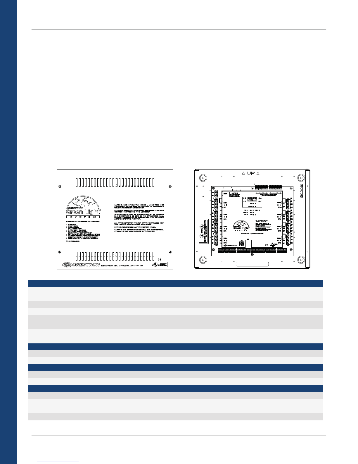
Room Solutions
Crestron Commercial Lighting Design Guide
GLPAC-DIMFLV
The GLPAC family is a Crestron Green Light integrated lighting system, designed for use as a standalone lighting controller in
classrooms, conference rooms, and even across multiple offices. While able to control 4 or 8 channels of dimmable fluorescent loads,
each GLPAC also provides a link to a centralized Crestron lighting control system for control and monitoring. Add optional real-time
power monitoring and Crestron RoomView Enterprise management software to help track and minimize energy usage facility-wide. The
GLPAC has a LAN port for fast communication with other control processors or directly with RoomView. Its two Cresnet ports allow one
remote connection to a centralized processor or another GLPAC and a local connection for keypads and touchpanels.
> Four or eight channels of 0-10 Volt fluorescent dimming
> Supports 100 to 277 Volt applications
> 16 Amp load rating per channel
> Built-in control system with Cresnet port
> Preloaded program for quick setup
> Optional real time power monitoring
> Control up to four rooms with a single GLPAC-DIMFLV
> Positive air gap at each output
Load Ratings
Dimmer Channels GLPAC-DIMFLV4(-PM): 4
GLPAC-DIMFLV8(-PM): 8
Per Channel 16 Amps at 100-277 Volts AC, 50/60 Hz
Dim Load Types 0-10 Volt fluorescent ballast (4-wire); 0-10V LED drivers; 60 mA max current sink
Switch Load Types Fluorescent Ballast, Incandescent, Magnetic Low-Voltage, Electronic Low-Voltage, Neon/Cold
Cathode, High-Intensity Discharge, Motor
Relay Lifetime Resistive rating: 100,000 on/off operations, 50A @ 277 VAC
General rating: 50,000 on/off operations, 16A @ 120/277 VAC
Power Requirements
Primary 100-277 Volts AC, 50/60Hz, supplied via channel 1 (L1, N1)
Available Cresnet Power 10 watts at 24 Volts DC, shared with occupancy and photocell sensor ports
Environmental
Temperature 32° to 104°F (0° to 40°C)
Humidity 10% to 90% RH (non-condensing)
Electrical Regulatory Certifications
UL508, Section 41 (Endurance Test) and Section 61C (Electronic Ballasts)
IEC60669-2-1, Section 19.102 (Contact mechanisms incorporated in electronic switches, intended for fluorescent lamp circuits or
other capacitive loads)
CE
> Phase-independent channels
> Local controls for setup, testing and verification
> Local and remote override capability
> Non-volatile power failure memory
> Four low-voltage 1A rated relays (-PM models only)
> Eight digital input ports
> Four occupancy sensor inputs and four photocell inputs
> Local Cresnet supports keypads, touchpanels, etc.
40
Page 45

Crestron Commercial Lighting Design Guide
GLPAC-DIMFLV Products
GLPAC-DIMFLV4 4 Dimmer Channels
GLPAC-DIMFLV4-PM 4 Dimmer Channels with power monitoring and four 1A rated relays
GLPAC-DIMFLV8 8 Dimmer Channels
GLPAC-DIMFLV8-PM 8 Dimmer Channels with power monitoring and four 1A rated relays
Flexibility
Each GLPAC can be used to control a single room, or up to four independent rooms. Single-room control is available right out of the box,
with no additional configuration. Multi-room control and other system adjustments are accomplished using local controls on the GLPAC
or via the built-in web interface. And because the GLPAC is a Crestron 2-Series control processor, limitless customization is possible for
specialized applications.
Save Energy
Enjoy a greener conscience with the GLPAC. Built-in support for occupancy sensing and daylight harvesting help control spending while
saving energy. Automatically turn off lights in unoccupied areas and maintain balanced bulb brightness with the natural light level in the
room. Crestron GLS sensors can be placed strategically in each space to maximize the benefits of energy management.
Built-in Power Monitoring (-PM models only)
Optional power monitoring tracks the real time energy usage of each load, thereby delivering statistics to help control energy costs. By
analyzing real data, organizations can make more educated decisions regarding energy resources, which will have greater impact on
the bottom line.
Easy Deployment
Packaged in one metal enclosure, the GLPAC can be deployed in small spaces, including plenum ceilings. The surface-mount GLPAC
can be affixed to a wall or ceiling rafter, cleanly out of sight. Standard wire-entry knockouts are provided.
Room Solutions
LIGHTING
LIGHTING
LIGHTING
LIGHTING
ELECTRIC
UTILITY
Example GLPAC-DIMFLV Application
+ -
+ -
78
+ 6
+ -
2 WIRING)
Y
-
ML
+
+ -
, SINK O
345
UT
-
P
+
CLASS 1 OR CLASS
(
2
-
+
MAX/OUT
A
1
1
0-10VDC
60m
UE
AL
V
MODE
K HOC
S
L
it breaker
CAUTION!
8888
gize unit.
F ELECTRICA
er
han one circu
RISK O
E
V
More t
SA
required to de-en
NEUT
LINE1
SW1
LINE2
SW2
LINE3
SW3
Multi-Room Lighting Controller with Power Management
LINE4
SW4
T
E
N
L
A
LOC
RRIDE
E
V
O
NET
SYS
CONT
-C
NET
CANCEL
-R
W
H
-R
W
S
PWR
OVR
NET-L
MSG
V4
PAC-DIMFL
16A PER CIRCUIT
GL
:
INPUT: 100 - 277 VAC 50/60 Hz
PES
, NEON/CC
Y
LV
MAXIMUM LOAD:
, E
LV
DIMMED LOAD TYPES:
, M
0-10 VDC FLUORESCENT BALLAST
SWITCHED LOAD T
INCANDESCENT
FLUORESCENT BALLAST, HID
®
LAN
USB
TACT C
CON
YS
A
L REL
GNA
SI
ED
T
S
LI
S
U
U
L
.
Q
C
E
.
CONT
IND.
48DO
S
ELL
C
O
T
PHO
ENSORS
S
OCC
LOSURES
PHOTOCELL
SENSOR
Color Key
Control
Sensors
AC
Cresnet
LAN
OCCUPANCY
SENSOR
LOW
VOLTAGE
SWITCHES
LAN
PC
MASTER
CONTROL
PROCESSOR
CONTACT
CLOSURE
41
KEYPADS
LIGHTS
LIGH
VOLUME
VOLUME
TEMP
TEMP
S
SHADES
T
TS
S
T
S
T
VAV
Page 46

iLux
iLux® is a complete, integrated lighting system designed for wall mount installation in boardrooms, auditoriums, theaters, or anywhere
versatile and cost-effective control of lighting and shades is required. iLux CLS-C6 is available with different options, including infiNET
EX wireless communications and motion detection.
x Wall mount integrated lighting and shade control
x 6 channels of dimming or switching
x 6 groups of shade and drape control
x Linkable for up to 54 lighting channels and 54 shade groups
x Up to 16 user-settable scenes
x 7 configurable "rocker" buttons with customizable labels
x Large ON and OFF buttons
x Flip-up front cover reveals setup controls and programming
port
Room Solutions
6 Channel Dimming
Six channels of dimming are available for incandescent, magnetic low-voltage, neon/cold cathode, and 2-wire dimmable fluorescent
loads. On/off switching of many non-dimmable lighting loads is also possible. Each channel will handle up to 800 watts individually,
with a total rating of 1920 watts for the complete unit. Larger loads and additional load types can also be supported using Crestron CLSEXP Series expansion modules.
6 Group Shade Control
Using Crestron networked shade and drape controllers, iLux enables versatile control of a roomful of motorized window treatments,
screens or lifts in up to six groups. Simply add a shade and drape controller from the Shades section.
Energy Management
With the addition of Green Light integration modules and light sensors, the iLux line of Integrated lighting systems allow for the
management of room occupancy sensing, daylight harvesting and demand response for maximum energy efficiency and cost savings
(ASHRAE 90.1 and CEC Title 24 compliant). See the Sensors section for more details.
Interface Support
The CLS line of room controllers can support up 2 touch panels and up to 16 keypads without a centralized processor. Individual buttons
can be programmed to work through the master unit or can target specific slave units for maximum control and room management.
Crestron Commercial Lighting Design Guide
x 6 bargraphs show lighting levels and shade positions
x Easy setup from front panel or iLux Designer software
x Built-in motion detector (-C6M and -C6MEX models only)
x Supports multipoint control using up to 16 keypads
x Optional IR remote
x Master air-gap relay
x Integrates with control systems via Cresnet
x Energy saving ASHRAE 90.1/LEEDS compliant
Available in almond, black, or white
x
iLux Room Controller (CLS-C6M)
42
Page 47

Crestron Commercial Lighting Design Guide
120
120 V
VAC
AC
CLS-C6M
iLux Integrated Lighting
System wi th Motion
Detector
CLS-C6
iLux Integrated
Lighting System
CNX-B6
6-Button
Designer
Keypad
CLS-IRHT8
iLux IR Handheld
Remote
C
KT
CKT 1
STRO
E
CR
1
N
4YZG
2
G
ET
Z
N
Y
24
TRONICS INC.N
LEC
NE
Example iLux Application
CKT
2
C
KT 2
VAC
20
1
C2N-SDC
-
SETUP
-
NET
A
R
ET
S
U
PW
7
64
J. 07
.
C2N-SDC
Shade and
Drape Controller,
120V AC
Color Key
Cresnet
LAN
Control
AC
CLS-EXP-DIM
C
K
T 3
CKT
4
C
KT
5
C
K
T
C
KT
3
C
KT 4
C
KT 5
6
C
K
T
6
X
MA
CENT
FF
ES
T O
CAND
CEN
IN
LD
S
NG
HO
S
MMI
I
E
FLUORE
HR
G
T
ENT D
RESC
DESCENT DIMMING
MLV DIMMIN
FLUO
CAN
RE
IN
60Hz
AC 60Hz
3 WI
V
AC
2/
77
0V
2
12
0-
T: 12
INPUT:
PU
OUT
iLux
DULE
O
M
N
IO
S
AN
EXP
CLS-EXP-DIM
N
RO
ST
CRE
120 - 277 VAC
Incandescent,
magnetic low-voltage,
neon/cold cathode
or 2-wire fluorescent
Room Solutions
iLux Room Controllers
CLS-C6 iLux CLSI-C6 iLux – International (230 V)
CLS-C6M iLux w/ Motion Detector CLSI-C6M iLux w/ Motion Detector – International (230 V)
CLS-C6EX iLux w/ infiNET EX CLSI-C6EX iLux w/ infiNET EX – International (230 V)
CLS-C6MEX iLux w/ Motion Detector & infiNET EX CLSI-C6MEX iLux w/ Motion Detector & infiNET EX – International (230 V)
Control System Integration via infiNET EX
TM
iLux Room Controllers with Crestron’s infiNET EX technology can wirelessly link to a 2-series control system. This two-way
communication link allows the iLux functions to be controlled from touchpanels, RF wireless remotes, and even computers. The control
system interface also enables flexibility for integration with other systems such as security, HVAC and energy management, plus remote
monitoring via Crestron RoomView applications.
Note: infiNET EX dimmers and switches are not able to communicate with the iLux directly, since both are “slave” modules.
Built-in Motion Detector
iLux Room Controllers with the built-in infrared motion detector can automate control based on room occupancy. iLux can turn on lights
and open shades automatically when someone enters the room or turn off and close them when the room is left empty.
Multi-Unit Expansion
One CLS-C6 type master will support up to eight additional CLS-C6 type units, allowing up to 54 lighting zones and 54 shade groups.
Commands for typical functions like scene recall, scene off, master dimming, and occupancy status are shared between the CLS-C6
units. Each unit can still support a complete assortment of local devices including keypads, shade controllers, and motion detectors.
43
Page 48

Crestron Commercial Lighting Design Guide
Expansion Modules
Expansion modules increase the amount of lighting loads controllable by a single CLS-C6 type unit. Expansion modules are listed in the
table below.
Expansion Module Load Function
CLS-EXP-DIM Supports incandescent, magnetic low voltage, neon/cold
cathode, and 2-wire and 3-wire dimmable fluorescent loads
Forward Phase Dimming
(16A per load)
120V, 230V, & 277V compatibility
CLS-EXP-DIMU Supports incandescent, magnetic low voltage, Electronic low
voltage, and 2-wire and 3-wire dimmable fluorescent loads
(16A per load)
Forward and Reverse-Phase Dimming
Auto Load Type Detection
120V, 230V, & 277V compatibility
CLS-EXP-DIMFLV Supports 4-wire Fluorescent, Incandescent, MLV and ELV
loads (16A per load)
120V, 230V, & 277V compatibility
0-10V Fluorescent Dimming plus High
Inrush Switching
CLS-EXP-DIMFDB Supports 3-wire Fluorescent Fluorescent Dimming
Expansion Module Example
LANLAN
DIMMING CONTROL
Room Solutions
Optional
Expansion
Modules
CLS-EXP-DIM
T MAX
CEN
S
T OFF
CEN
INCANDE
RES
HOLD
S
E
UO
FL
THR
V DIMMING
ML
E F
NCANDESCEN
I
WIR
3
2/
12
INPUT:
OUTPUT: 120
iLux
UL
D
MO
ION
EXPANS
ESTRON
CR
CLS-EXP-DIMU
X
MA
ENT
SC
E
T OFF
N
CE
NCAND
I
HOLD
S
UORES
FL
HRE
T
MLV DIMMING
E F
INCANDESCENT DIMMING
WIR
3
2/
12
T:
T:
INPU
TPU
OU
iLux
N MODU
IO
EXPANS
RON
CREST
Incandescent,
magnetic low-voltage,
neon/cold cathode
or 2-wire fluorescent
120 - 277 VAC
IMMING
D
MMING
T
DI
T
SCEN
E
UOR
L
60Hz
AC
V
7
0VAC 60Hz
-27
E
-DIM
XP
-E
CLS
Universal Dimming
(Forward and Reverse phase)
Auto Adapt to load type
120 - 277 VAC
MING
IM
SCENT D
UORE
L
z
z
60H
AC 60H
V
AC
7
0V
27
-
120
E
L
IMU
CLS-EXP-D
All 4-Wire Fluorescent
High In-Rush Switching
CLS-C6M
Color Key
LAN
Cresnet
AC
CLS-EXP-DIMFDB
44
CLS-EXP-DIMFLV
X
NT OFF
CE
INCANDESCENT MA
LD
HO
S
UORES
FL
THRE
ML
NCAND
I
3
2/
NPU
I
OUTPU
iLux
ION M
EXPANS
RON
ST
CRE
T OFF
CEN
LD
S
ESHO
UORE
FL
HR
T
3 WI
INPUT
OU
iLux
ON M
EXPANSI
N
RO
T
S
RE
C
120 - 277 VAC
MING
ING
IM
M
DIM
ENT D
T
SC
DIMMING
ESCEN
V
UORE
L
z
z
E F
60H
60H
WIR
AC
AC
V
7
0V
-27
12
T:
120
T:
E
L
ODU
V8
L
IMF
-EXP-D
CLS
3-Wire Fluorescent
G
MIN
120 - 277 VAC
DIM
T
UORESCEN
FL
60Hz
60Hz
RE
AC
7 V
VAC
-27
: 120
120
PUT:
T
E
UL
OD
3W
F
-DIM
XP
-E
CLS
Page 49

Crestron Commercial Lighting Design Guide
Cameo Dimmers and Switches
Cameo® dimmers and switches are designed to replace any
standard in-wall dimmer or switch. Although the following
devices are functional as a standalone dimmer or switch, they
deliver greatly enhanced functionality as part of a complete
Cameo Dimmer
with 2-way rocker
(depicted with face plate)
Crestron control solution. When connected to a Crestron PAC2 or
PAC2M automation control system (or any other 2-Series control
system), extensive automation and control capability is enabled.
In addition to replacing standard dimmers and switches, Cameo
remote “slave” units replace traditional 3- or 4-way lighting
dimmers and switches. The slave units connect to the main
dimmer or switch through the 120 Volt traveler wire. Up to 10
slave units can be connected to a single Cameo dimmer or
switch.
Dimmer Derating
Dimmers generate heat during operation. When dimmers are placed in close proximity, such as in a wall-box, their ability to
dissipate heat is reduced. To increase lifetime and avoid overheating, the max load ratings are reduced accordingly. For each
dimmer there are three ratings: single, one side shared, and two sides shared. See the derating graphics below for examples.
Cameo Switch
with 2-way rocker
(depicted with face plate)
Room Solutions
750VA
CEN-RFGW-EX
CEN-RFGW-EX
LAN PoE
CRESTRON
ACTIVITY
PWR
NET
ACQUIRE
SETUP
NET
G Z Y 24
Maximum Loads for Cameo Dimmer/Switch Combos Maximum Loads for Cameo Dimmers
600VA
600VA
600VA 600VA400VA
DIM
500 VA
SW
1 A
DIM
400 VA
SW
1 A
DIM
400 VA
SW
1 A
DIM
400 VA
SW
1 A
DIM
250 VA
SW
1 A
DIM
400 VA
SW
1 A
Example Cameo Dimmers and Switches Application
Color Key
Cresnet
AC
2W
CONTROL
SYSTEM
CLW-DIMEX-P
CLW-SLV-P
120 VAC
CLW-SLV-P
LIGHTINGLIGHTING
EXHAUST
FAN
CLW-DIMSWEX-P
LIGHTS
FAN
45
Page 50

Crestron Commercial Lighting Design Guide
Cameo Dimmers & Switches
Model Name
Communication
Loads
Rating (VA=Watts for Incandescent)
Rating with one side shared
Rating with two sides shared 400 VA 1000 VA*, Motor: ½ HP Dim: 250 VA, Switch: 1 Amp Switch: 300 VA, Fan: 1.5 A
Slave Capable (CLW-SLV-P) Yes Yes No No
Operating Voltage 120 VAC 120 VAC 120 VAC 120 VAC
Incandescent s s s s
Tungsten-Halogen s s s s
Magnetic Low Voltage s s s s
Dimmable CFL s s
CFL s s s
LED
Pinhole LED Color White White White White
7 level bar graph
1 pinhole LED s
Room Solutions
Button Choices
Rocker s s s
Up to 2 Buttons
Up to 4 Buttons s s s
Available Colors
White (Glossy) s s s s
White (Matte)
Almond (Glossy) s s s s
Almond (Matte) s s s s
Black (Glossy) s s s s
Black (Matte) s s s s
Latte (Matte) s s s s
Dusk (Matte) s s s s
Gray (Glossy) s s s s
Ivory (Glossy) s s s s
Dark Almond (Glossy) s s s s
Brown (Glossy) s s s s
* Rating is 600 VA when using electronic ballasts or CFL loads.
Dimmer Switch
CLW-DIMCN-P (Wired)
CLW-DIMEX-P (Wireless)
Cresnet (Wired)
infiNET EX (Wireless)
750 VA 1000 VA*, Motor: ½ HP Dim: 500 VA, Switch: 1 Amp Switch: 300 VA, Fan: 1.5 A
600 VA 1000 VA*, Motor: ½ HP Dim: 400 VA, Switch: 1 Amp Switch: 300 VA, Fan: 1.5 A
s s s
s s s s
CLW-SWCN-P (Wired)
CLW-SWEX-P (Wireless)
Cresnet (Wired)
infiNET EX (Wireless)
s
Dimmer and Switch
Combo
CLW-DIMSWCN-P (Wired)
CLW-DIMSWEX-P (Wireless)
Cresnet (Wired)
infiNET EX (Wireless)
Fan and Switch
Combo
CLW-FANSWCN-P (Wired)
CLW-FANSWEX-P (Wireless)
Cresnet (Wired)
infiNET EX (Wireless)
46
Page 51

Crestron Commercial Lighting Design Guide
Cameo Express Dimmers & Switches
Wireless
Model Name
Communication
Loads
Rating (VA=Watts for Incandescent) 750 VA 1000 VA*, Motor: ½ HP Dim: 500 VA, Switch: 1 A Switch: 300 VA, Fan: 1.5 A
Rating with one side shared
Rating with two sides shared 400 VA 1000 VA*, Motor: ½ HP Dim: 250 VA, Switch: 1 A Switch: 300 VA, Fan: 1.5 A
Slave Capable (CLW-SLV-P) No No No No
Operating Voltage 120 VAC 120 VAC 120 VAC 120 VAC
Incandescent s s s s
Tungsten-Halogen s s s s
Magnetic Low Voltage s s s s
Dimmable CFL s s
CFL s s s
LED
Pinhole LED Color Green Green Green Green
7 level bar graph
1 pinhole LED s
Button Choices
Rocker s s s
Up to 2 Buttons
Up to 4 Buttons s s s
Available Colors
White (Glossy) s s s s
White (Matte)
Almond (Glossy) s s s s
Almond (Matte)
Black (Glossy) s s s s
Black (Matte)
Latte (Matte)
Dusk (Matte)
Gray (Glossy)
Ivory (Glossy)
Dark Almond (Glossy)
Brown (Glossy)
* Rating is 600 VA when using electronic ballasts or CFL loads.
Dimmer Switch
CLW-DIMEX-E CLW-SWEX-E CLW-DIMSWEX-E CLW-FANSWEX-E
infiNET EX infiNET EX infiNET EX infiNET EX
600 VA 1000 VA*, Motor: ½ HP Dim: 400 VA, Switch: 1 A Switch: 300 VA, Fan: 1.5 A
s s s
s
Dimmer and Switch
Combo
Fan and Switch
Combo
Room Solutions
47
Page 52

Processors
PAC2
The PAC2 is a professional dual bus control system designed
to serve as the central processor for Crestron Green Light
systems. Fast performance, rigorous construction, and
extreme flexibility provide a truly powerful automation
solution for today's most demanding commercial
environments.
The PAC2 is extensively programmable using Crestron’s
suite of development software. It works seamlessly with
Crestron’s entire line of dimmers, shade controllers,
keypads, touchpanels, thermostats, wireless gateways,
control cards, and expansion modules.
Design Recommendations: The PAC2 is limited by how many Cresnet addresses are available. There are initially 252 available Cresnet
addresses (NET IDs 03 to FE). Each keypad, touchpanel, shade controller, and lighting module uses a Cresnet address. The total number
of these devices must not exceed 252.
Control Ports: 1 10/100 Ethernet port (2 with C2ENET-2), 8 relays, 8 analog/digital input or digital output ports, backup net input,
override input, fault notify output, 32 Cresnet ports in eight independent segments.
Installation: Installs in a CAEN enclosure. Crestron recommends a separate cabinet just for the PAC2. This way there is a simplified
low-voltage wiring cabinet.
Processors
Power: The PAC2 comes with a built-in power supply that connects to an AC power source.
Processor
CPU 32-bit Freescale ColdFire Microprocessor
Memory
SDRAM 64 MB
NVRAM 256 KB
Flash 4 MB
Compact Flash Expandable up to 4 GB (not included)
Operating System
Real-time, preemptive multi-threaded/multitasking kernel; FAT32 file system with long names; supports SIMPL™ Windows® and
SIMPL+®
Ethernet
With C2ENENT-1 10/100Base-T, auto-negotiating, full/half duplex, static IP or DHCP/DNS, SSL, TCP/IP, UDP/IP, CIP,
With C2ENET-2 All above features plus built-in firewall, router, and network address translator (NAT)
Power Requirements
Main Power Consumption 2.4 Amps, 100-250 Volts AC, 50/60 Hz
Available Cresnet Power 50 Watts (shared with control card expansion slots)
Environmental
Temperature 41° to 113°F (5° to 45°C)
Humidity 10% to 90% RH (non-condensing)
Weight
8.0 lb (3.62 kg) – with line cord
Crestron Commercial Lighting Design Guide
SMTP, SNMP, built-in web server and e-mail client; supports Crestron e-Control2 XPanel and
RoomView Applications
4
Page 53

Crestron Commercial Lighting Design Guide
PAC2M
The PAC2M is a compact, low-cost alternative to the PAC2 designed for small
lighting and automation applications. At half the size of a PAC2, the PAC2M is
perfect for individual meeting rooms and lecture halls.
The PAC2M is extensively programmable using Crestron’s suite of development
software. It works seamlessly with Crestron’s entire line of dimmers, shade
controllers, keypads, touchpanels, thermostats, wireless gateways, control
cards, and expansion modules.
Design Recommendations: The PAC2M is limited by how many Cresnet
connections are available. There are two isolated network segments, each
supporting up to 25 Cresnet devices. Therefore, the PAC2M can control up to 50
total keypads, touchpanels, shade controllers, and lighting modules.
Control Ports: 1 10/100 Ethernet port, 4 relays, 4 digital inputs, override input,
8 Cresnet ports in 2 independent segments.
Installation: Installs in a CAEN enclosure or mounts directly to a surface without
an enclosure.
Power: The PAC2M requires a separate supplemental power supply. It is recommended that the power fed to the PAC2M comes from a
clean and uninterrupted source. Remaining power is shared over the Cresnet ports.
Processor
CPU 32-bit Freescale ColdFire Microprocessor
Memory
SDRAM 32 MB
NVRAM 256 KB
Flash 8 MB
Removable Flash Expandable up to 1 GB using MMC compatible card (not included)
Operating System
Real-time, preemptive multi-threaded/multitasking kernel; FAT32 file system with long names; supports SIMPL™ Windows® and
SIMPL+®
Ethernet
10/100Base-T, auto-negotiating, full/half duplex, static IP or DHCP/DNS, SSL, TCP/IP, UDP/IP, CIP, SMTP, SNMP, built-in web server
and e-mail client; supports Crestron e-Control2 XPanel and RoomView applications
Power Requirements
Main Power Consumption 5 Watts (0.21 Amps) @ 24 Volts DC; (Power supply sold separately)
Available Cresnet Power 45 Watts using PW-2420RU or larger (sold separately)
Environmental
Temperature 41° to 113°F (5° to 45°C)
Humidity 10% to 90% RH (non-condensing)
Weight
2.14 lbs (0.97 kg)
Processors
49
Page 54

IPAC-GL1
The Crestron IPAC is a 2-Series control processor designed for wall mount installation. Its front panel controls and LCD display deliver a
user-friendly interface for out-of-the-box system setup. Built-in Ethernet, Cresnet, RS-232, relay, and sensor inputs provide direct
connectivity for interfacing with all kinds of devices, controls, and networks. The onboard e-Control® Web server allows for complete
integration as part of a facility-wide managed control network.
Design Recommendations: The total number of Cresnet devices should not exceed 60.
Dimmed and Switched Load Amounts: Up to 210 loads
Keypad Amounts: 16
Touchpanel Amounts: 2
Control Ports: 1 Cresnet port, 1 10/100 Ethernet port, 2 bi-directional RS-232 ports, 4 relays, 4 digital or analog inputs
Other: 500 time clock events, up to 30 occupancy sensors and photocell sensors
Power: The IPAC-GL1 requires a separate supplemental power supply. It is recommended that the power fed to the IPAC-GL1 comes
from a clean and uninterrupted source.
Processors
Processor
CPU 32-bit Freescale ColdFire Microprocessor
Memory
SDRAM 32 MB
NVRAM 1 MB
Flash 8 MB
Power Failure Memory 10 years
Operating System
Real-time, preemptive multi-threaded/multitasking kernel; FAT32 file system with long names; includes default program for Green
Light Power Switching systems
Ethernet
10/100Base-T, auto-negotiating, full/half duplex, static IP or DHCP/DNS, SSL, TCP/IP, UDP/IP, CIP, SMTP, SNMP, built-in web server
and e-mail client; supports Crestron e-Control2 XPanel and RoomView Applications
LCD Display
Green LCD dot matrix, 128 x 64 resolution, adjustable LED backlight
Power Requirements
Main Power Consumption 10 Watts (0.42 Amps) @ 24 Volts DC; (Power supply sold separately)
Available Cresnet Power 40 Watts using GLA-PWS50 power supply (sold separately)
Environmental
Temperature 32° to 104°F (0° to 40°C)
Humidity 10% to 90% RH (non-condensing)
Heat Dissipation 20 BTU/Hr
Testing & Compliance
UL listed, FCC Part 15, CEC Title 24
Crestron Commercial Lighting Design Guide
Page 55

Crestron Commercial Lighting Design Guide
DIN-AP2
The DIN-AP2 is a 2-Series control processor designed for small to medium-sized lighting and automation applications. DIN rail mounting
enables modular installation alongside Crestron DIN Rail lighting and automation control modules and other third-party DIN rail
mountable devices.
Design Recommendations: The total number of Cresnet devices should not exceed 60. Hub recommended for more than 20 devices.
Dimmed and Switched Load Amounts: Up to 210 loads
Keypad Amounts: 16
Touchpanel Amounts: 2
Control Ports: 2 Cresnet ports, 1 10/100 Ethernet port, 2 bi-directional RS-232 ports, 4 IR/serial ports, 4 low-voltage relays, 8 Versiport
I/O ports
Other: 500 time clock events, up to 30 occupancy sensors and photocell sensors
Power: The DIN-AP2 requires a separate supplemental power supply. It is recommended that the power fed to the DIN-AP2 comes from
a clean and uninterrupted source.
Processor
CPU 32-bit Freescale ColdFire Microprocessor
Memory
SDRAM 32 MB
NVRAM 256 KB
Flash 8 MB
Removable Flash Expandable up to 2 GB using MMC compatible card (not included)
Operating System
Real-time, preemptive multi-threaded/multitasking kernel; FAT32 file system with long names; supports SIMPL™ Windows® and
SIMPL+®
Ethernet
10/100Base-T, auto-negotiating, full/half duplex, static IP or DHCP/DNS, SSL, TCP/IP, UDP/IP, CIP, SMTP, SNMP, built-in web server
and e-mail client; supports Crestron e-Control2 XPanel and RoomView Applications
Power Requirements
Cresnet Power Usage 8 Watts (0.33 Amps @ 24 Volts DC)
Environmental
Temperature 32° to 104°F (0° to 40°C)
Humidity 10% to 90% RH (non-condensing)
Heat Dissipation 26 BTU/Hr
Weight
9.8 oz (277 g)
Processors
Page 56

Crestron Commercial Lighting Design Guide
TPS--44L
TPMC
-4SM
User Interfaces
Crestron has an unparalleled selection of user interfaces, from touchpanels to keypads to PCs. Listed in this section are select products
that work well in commercial lighting installations. Other user interfaces are available and can be found at www.crestron.com.
Keypads are a simple and cost effective interface for classrooms and small offices. Touchpanels are powerful, user friendly tools that
work well in hotel rooms, lecture halls, and conference rooms. Use both keypads and touchpanels together for ultimate control.
Wired Touchpanels
T
x 3.6" active matrix color touchscreen display
x 16-bit Isys graphics
x 320 x 240 resolution
x Synapse Image Rendering Algorithm
x 10 white backlit pushbuttons and engravable faceplate
x WAV file audio feedback
x Ethernet and Cresnet communications
x Stylish flush wall mount design
x 10 designer colors
User Interfaces
T
-
x Modern, contoured appearance
x Thin profile and small footprint
x Affordable and easy to install
x 4.3" widescreen color touchscreen
x 16-bit Isys i/O graphics
x 800 x 480 resolution
x DNav dynamic menu objects
x Streaming video
x Crestron IP intercom
x WAV file audio feedback
x Built-in microphone and speaker
x Built-in proximity sensor
x 10 optional "hard key" pushbuttons
x Dual-color button backlighting and feedback
x Engravable button text
x RoomView room scheduling mode
x Room occupancy sensor option
x Single-wire Ethernet connectivity
x PoE network powered
x Available in gloss black or white
x Fits in a horizontal 1-gang or Euro back box
x Available tabletop and multi-surface mount kits
52
Page 57

Crestron Commercial Lighting Design Guide
TPS--6 & TPSS-66L
TPMC--8T & TPMC--8L
x TPS-6: 45 degree tilt mount for tabletop use
x TPS-6L: flush mount for in a wall, lectern, or similar flat surface
x 5.7" active matrix color touchscreen display
x 16-bit Isys graphics
x 640 x 480 resolution
x DNav dynamic menu objects
x Synapse Image Rendering Algorithm
x Single full-motion, fully-scalable video
x High-speed Ethernet and Cresnet communications
x Button engraving available as solid or backlit text
x CAT5 AV video connectivity
x Low-profile single-wire connection
x WAV file audio feedback
x Built-in light sensor
User Interfaces
x TPMC-8T: for fixed tabletop use
x TPMC-8L: flush mount for in a wall, lectern, or similar flat surface
x 8.4" active matrix touchscreen display
x 16-bit Isys i/O graphics
x 800 x 600 SVGA resolution
x Synapse image rendering algorithm
x DNav dynamic menu objects
x Windows XP Embedded operating system
x Onboard PC applications for web browsing, streaming media,
conferencing, VoIP, and remote computer access
x Streaming video from network cameras and servers
x Direct panel-to-panel intercom over IP
x Built-in microphone and stereo speakers
x 5-way thumb pad and 4 "hard key" buttons
x Includes stylus with onboard storage slot
x Built-in biometric fingerprint scanner
x Wired 10/100 Ethernet and 802.11a/b/g Wi-Fi communications
53
Page 58

Crestron Commercial Lighting Design Guide
V12 & V15
TPMC--33X
V
x Available in tabletop or flush mount
x V12: 12" touchscreen display, 800 x 600 SVGA resolution
x V15: 15” touchscreen display, 1280 x 768 WXGA resolution
x Sleek, beautiful, versatile
x High-performance graphics and video
x Industry's only HDCP-ready touchpanel controller
x VESA-compatible mounting affords endless install options
x Tabletop tilt model features clean, modern design
x Wall mount model installs flush in shallow spaces
x Contemporary appearance blends in anywhere
x Significantly reduced wiring via DigitalMedia technology
x Digital Graphics Engine (DGE) installs up to 200 ft away
x Also works with the DVPHD Digital Video Processor
x Built-in microphone and speakers
x USB keyboard/mouse port
x Cool, quiet fan less design
x Available in white or black
Handheld Wireless Touchpanels
T
User Interfaces
x Sleek and ergonomic handheld design
x Elegant gloss black finish
x Instant-Waking behavior with tilt sensor
x Works like an IR remote - with all the benefits of 2-way RF
x High-performance 802.11a/b/g Wi-Fi wireless communications
x 50 feet omnidirectional RF range indoors
x Roaming between multiple Wi-Fi access points
x Wireless video from network cameras and servers
x Built-in speaker and microphone
x Crestron wireless IP Intercom capability
x WAV file customizable audio feedback
x Widely-spaced tactile pushbuttons
x White EL backlit button text
x 2.8" active matrix color touchscreen display
x Wide 150 degrees viewing angle
x 16-bit Isys i/O graphics
x 240 x 320 resolution
x DNav Dynamic Menu Objects
x Synapse Image Rendering Algorithm
x Programmable via SystemBuilder and Adagio Composer software
x Long-lasting LiPo rechargeable battery pack
x Stylish tabletop docking station included
Wall mount docking station also available
x
54
Page 59

TPS-6X
Crestron Commercial Lighting Design Guide
x Lightweight contoured design for wireless handheld use
x Also affords full-featured tabletop tilt touchpanel operation
x Elegant gloss black, gloss white, or matte black finishes
x Non-slip rubber grips on rear
x Illuminated buttons and engravable backlit text
x 5.7" active matrix color touchscreen display
x 16-bit Isys graphics
x 640 x 480 resolution
x Dynamic graphics & text capability
x DNav dynamic menu objects
x Synapse Image Rendering Algorithm
x Displays full-motion video while docked
x High-power, high-speed 2.4 GHz RF wireless technology
x Up to 200 feet RF range indoors
x Supports roaming for extended RF coverage
x 1-way IR wireless capability also built in
x Includes tabletop tilt docking station, interface module, and NiMH
rechargeable battery pack
x Wired Ethernet, Cresnet, and CAT5 video connectivity
x No-button front bezel option
User Interfaces
TPMC-8X
x Stylish and compact ergonomic design
x 8.4" active matrix touchscreen display
x 16-bit Isys i/O graphics
x 800 x 600 SVGA resolution
x Synapse image rendering algorithm
x DNav dynamic menu objects
x 802.11a/b/g Wi-Fi 2-way wireless communications
x Windows XP Embedded operating system
x Onboard PC applications for web browsing, streaming media,
conferencing, VoIP, and remote computer access
x Wireless video from network cameras and servers
x Direct panel-to-panel intercom over IP
x Built-in microphone and stereo speakers
x 5-way thumb pad and 4 "hard key" buttons
x Includes stylus with onboard storage slot
x Built-in biometric fingerprint scanner
x Internal Li-Ion battery pack included
x External "booster" battery pack available
x Optional desktop and wall mount docking stations
55
Page 60

Keypads
Cameo
User Interfaces
Standard Mount
C2N-CBD-TS & INET-CBD
Flush Mount
C2N-CBF-T
Crestron Commercial Lighting Design Guide
Crestron Cameo presents a fresh, innovative concept in keypad
design featuring an incredibly small footprint and slim profile with
versatile button configurations. Use Cameo keypads as a simple
interface for controlling lights, shades, motors, or even an AV
system connected to the control system.
Cameo Standard Mount (C2N-CBD-TS)
The C2N-CBDinstallation in a conventional electrical gang-b
faceplate (shown in picture but not included). New gloss and
matte finishes match perfectly with popular off-the-shelf decorator
faceplates. Available in a variety of designer colors, the gloss
finish has a slick, glossy appearance, while the matte finish
achieves a softer, satiny look.
.
Cameo Standard Mount w/infiNET EX (INET-CBDEX)
Cameo is also available with infiNET EX in the INET-CBDEX. The
INET-CBDEX is a standard mount Cameo keypad with similar*
features as the C2N-CBDgroundbreaking infiNET EX wireless technology affords
way communications throughout a home or office structure
without the need for physical control wiring. Employing a 2.4 GHz
esh network topolog
m
RF extender, increasing effective range an
complete network by providing multiple redundant signal paths
within the m
Cameo Flush Mount (C2N-CBF-T)
The Cameo unique flush mount design affords a very discreet
appearance occupying just one-third the space of a conventional
keypad. Employing a smart spring clamp mounting system, the
C2N-CBF-T Cameo Flush Mount model installs easily in drywall
without requiring a backbox. Five designer colors are available,
each with a satiny, textured finish
Customizable Buttons
Exquisitely simple yet highly customizable, a single Cameo keypad
can be configured easily by the installer to provide from two to six
buttons. There are three button sizes: small (1/6 keypad height),
medium (1/3 keypad height), and large (1/2 keypad height).
TS is a standard mount model designed for
y, every infiNET EX device functions as an
esh network.
ox using a
TS, plus infiNET EX. Crestron's
d reinforcing the
decorator
reliable 2-
Auto-dimming Backlight
Cameo's high-quality backlit laser engraving provides customizable button text that's easy to read under any lighting condition. A builtin light sensor controls the backlight intensity automatically to achieve a crisp, legible appearance in both darkened and fully lit rooms.
Contact Closure Inputs
Two sensing inputs are included on the rear of the keypad to provide a simple and convenient interface for low voltage contact-closure
devices such as occupancy sensors, door switches, and motion detectors.
*Note: Contact closure inputs not available on the wireless infiNET EX model.
5
Page 61

Crestron Commercial Lighting Design Guide
Enhanced LED Feedback
Six pinhead-sized bright white LED light pipes provide elegant and versatile button feedback. Ten different blink patterns are built-in,
enabling blinking LED feedback while simplifying programming and minimizing traffic on the Cresnet network. Built-in bar graph logic
allows the feedback LEDs to function as a 6-segment bar graph display to provide a visible level indication when adjusting lighting and
audio settings. The overall LED intensity is auto-dimmable, adjusting automatically for optimal visibility under varying lighting
conditions.
Ambient Light Sensor
In addition to controlling Cameo's backlight and LED intensity, the built-in light sensor can also be utilized by the control system to
support daylight harvesting and other programmatic functions.
Example Cameo Keypad Application
LIGHTS ON
LIGHTS OFF
S
SHADE
S
VOL
SHADE
T
HTT-B10EX
The HTT-B10EX is a stylish compact wireless pushbutton controller with
10 multi-function buttons, custom backlit engraving, white LED
feedback, and infiNET EX wireless technology. Perfect for desktops,
podiums, or anywhere else a simple, unobtrusive controller is needed
without running any wires.
x 10 engravable backlit buttons
x Configurable for up to 3 functions per button
x White LED lightpipe feedback indicators
x True-feedback and dual-bargraph capability
x infiNET EX 2-way wireless communications
x Powered by batteries or external power pack
x Wakes instantly when touched or picked up
x Auto-dimmable backlight and LED intensity
x Available in black or white
MUTE
VOL
ALL ON
DIM
T
PATH
S
LIGHTS
T
LIGHTS
FAN HIGH
FAN LOW
FAN OFF
ALL OFF
SCREEN
VOL
VOL
S
T
User Interfaces
57
Page 62

Decorator
Crestron Commercial Lighting Design Guide
Crestron C2N-DB Decorator Series keypads deliver versatile keypad control
with contemporary styling to support a broad range of applications from
lighting to AV distribution.
Available in configurations of 6, 8, or 12 buttons, Decorator keypads are
designed to allow installation in perfect harmony with non-Crestron devices
using readily available decorator style faceplates (not included). Mountable
in a standard electrical gang box, multiple keypads can easily be ganged
side-by-side along with other wall mount devices. All button caps are
engravable and include integral red LED light pipe feedback indicators.
Features
x Fits standard electrical gang boxes and decorator faceplates
x Available in 6, 8, and 12 button configurations
x Replaceable, custom-engravable button caps
x Programmable feedback LEDs
x Available in black, gloss white, and gloss almond
x Easy Cresnet wiring
C2N-DB Mounting
User Interfaces
5
Page 63

Designer
Crestron Commercial Lighting Design Guide
The CNX-B Designer series wall mount keypads are available in configurations of 2, 4, 6, 8, or 12
buttons. Buttons are large for optimal ergonomics. Each model mounts in a standard electrical gang
box and includes a matching 1-gang faceplate. Optional 2 and 3-gang faceplates are available to
allow up to three keypads to be installed side-by-side. Optional Designer and Architectural
faceplates are offered in a variety of elegant finishes. Button caps are engravable and include LED
feedback indicators. Standard models are available in White, Black or Almond. Backlit button caps
are also available (black only).
CNX-B series keypads include built-in WAV sound file capability to enable customized audible
feedback. An onboard temperature sensor is also included for general monitoring of room
temperature. The product name corresponds to the number of keypad buttons. For example,
CNX-B6 is a six-button keypad and a CNX-B12 is a 12-button keypad.
The CNX-B series keypads have a uniquely stylish shape, and faceplates are available for single,
double, or three gang p
Features
x Available with 2, 4, 6, 8, or 12 buttons
x Colors include matte white, matte almond, or black
x Metal faceplate options:
- Black Chrome - Brushed Gold
- Polished Black - Polished Gold
- Polished Brass - Stainless Steel
x Primed faceplate available
x All keypads can be custom engraved
x All keypad buttons are backlit capable and have a variable intensity, independently
addressable and programmable LED that serves as a user feedback indicator
Crestron keypads can
standard electrical junction boxes. Custom multi-gang plates are required.
late arrangements.
be ganged in one, two or three gang configurations and are mounted in
CNX-B Mounting
User Interfaces
5
Page 64

Mobile Interfaces
Crestron Mobile Pro®
Mobile Pro brings the power of a Crestron touchpanel right to your
®
or iPod® touch. Using Mobile Pro, you can talk to a 2-series
iPhone
control processor from either an 802.11 (Wi-Fi) connection or your
cellular network. Total control is always at your fingertips.
One interface can control multiple locations, such as different buildings
across an enterprise. The graphical interface provides real-time status of
room temperature, lighting levels, media information, and more. Control
lights, AV systems, and anything else connected to your Crestron system
right from your mobile device.
Mobile Pro is available from the iTunes
include the iPod touch and all iPhone models up to the iPhone 4.
Crestron Mobile Pro G
Mobile Pro G has the same features of Mobile Pro, but with a higher
resolution designed for the iPad
XPanel & XPanel for Mac
Transform any computer into a virtual Crestron touchpanel - including the iMac® and MacBook®. Take control of your Crestron system
from any computer around the office, classroom, or world. Effortlessly bring touchpanels to the desktop of Windows
native Crestron support. Augment existing systems to add more control in more places, or use any computer as a main control interface,
making a complete control solution extremely affordable. XPanel works right from a web browser for control from anywhere.
XPanel is a software application which connects to any Crestron 2-Series control system. Through a secure Ethernet connection, XPanel
User Interfaces
sends and receives data to and from the control system based on user commands. A customized XPanel data file resides on the control
system. This translates into an experience as simple as using a touchpanel.
In the Office
x Control lights, climate, music & more from a computer or laptop
x Extend total office control to the home without the need of an additional touchpanel
x Retain the same look that exists on other touchpanels around the office
In the Classroom
x Use existing computers in the classroom to control the projector, audio, and lights
x Connect more classrooms today using the software application; add touchpanels or keypads as the budget allows
x Password protection keeps unwanted users from controlling the system
Custom Graphics
Make custom graphics with Crestron software tools to keep a consistent look and feel across all user interfaces. XPanel is natively
supported in VT Pro-e.
Crestron Commercial Lighting Design Guide
®
App Store. Supported products
TM
.
®
or Mac OS® X with
60
Page 65

Crestron Commercial Lighting Design Guide
GLS-ODT & GLS-OIR
Sensors
Adding sensors makes a smart system even smarter. Sensors save on energy costs while enhancing functionality and reliability.
The Sensor Advantage
x Reduced energy usage
x More consistent lighting levels
x Completely automatic
Automated Actions
A system with sensors will automatically control lights based on occupancy. When no one is in a room, lights shut off and energy is
conserved. Sensors also help with light harvesting by monitoring ambient light. A system with sensors can ramp the artificial lighting up
or down depending on the amount of natural light entering a room. This allows consistent lighting conditions while maximizing energy
savings. Since everything is automatic, human error is eliminated.
Occupancy Products
Crestron Green Light sensors deliver a powerful solution for reducing
energy costs and enhancing the functionality of li
environmental systems. Crestron offers ceiling and wall mount occupancy
sensors for areas up to 2500 square feet.
Advanced self-adaptive motion sensing using a combination of ultrasonic
and passive infrared technologies affords extreme reliability for control of
lighting, climate control and other devices in the room. A built-in photocell
can be set to override the occupancy sensor if the ambient light level is
above a set threshold, preventing lights from turning on when there is
sufficient daylight in the room.
Sensors are easily connected to the lighting control processor via the
Cresnet control network using a GLS-SIM Sensor Integration Module.
Alternately, they may be connected directly via an input port.
Model Sensor Type Mount Type Coverage Area Coverage Pattern
GLS-ODT-C-500
GLS-ODT-C-1000
GLS-ODT-C-2000
GLS-ODT-W-1200
GLS-OIR-C-450
GLS-OIR-C-1500
GLS-OIR-W-2500
Ultrasonic and infrared Ceiling 500 sq ft 180 degrees
Ultrasonic and infrared Ceiling 1000 sq ft 360 degrees
Ultrasonic and infrared Ceiling 2000 sq ft 360 degrees
Ultrasonic and infrared Wall 1200 sq ft 110 degrees
Infrared Ceiling 450 sq ft 360 degrees
Infrared Ceiling 1500 sq ft 360 degrees
Infrared Wall 2500 sq ft 110 degrees
ghting and
Sensors
61
Page 66

Crestron Commercial Lighting Design Guide
Light Sensors
GLS-LCL & GLS-LOL
Crestron Photocell Light Sensors are designed for daylight harvesting
GLS- LCL GLS-LOL
Model Type Location Field of View Light Sensitivity
GLS-LCL
GLS-LOL
Closed-Loop On Ceiling Above Work Area 60 degree cone, aimed straight down 0 to 70 foot candles
Open-Loop On Ceiling Near Window 60 degree cone, aimed 45 degrees down 3 to 6000 foot candles
GLS-LEXT
applications to control the balance of natural and artificial lighting in an
indoor space. By harnessing natural daylight from windows and skylights,
electrical lighting can be turned off or dimmed, reducing energy usage
while maintaining a consistent light level for a more efficient and
comfortable work space. Outdoor lighting may also be turn off and on
automatically using a photocell light sensor.
The GLS-LCL is used to monitor and adjust based on the reflected light
levels at a certain location, such as a desk. The GLS-LOL is used to look
at a window and monitor how much light is entering from outside.
Sensors
Partition Products
GLS-PART
Surface mount partition sensor easily connects to the GLS-SIM or control processor to manage divisible room environments. When
installed as part of a Green Light system, it allows the control system to divide the lighting controls according to the current room
configuration.
Sensor Interfaces
GLS-SIM
The GLS-SIM is a compact interface device designed to allow Crestron Green Light
sensors to connect directly to a Cresnet control network. The GLS-SIM installs easily at
the sensor location, mounting conveniently inside the electrical box or exposed above
the ceiling. Wiring connections to the network and sensor are facilitated using miniature
screw terminals.
The GLS-SIM is compatible with Crestron GLS-series sensors, as well as with most 24
Volt powered sensors from any manufacturer. Up to 1A at 24 VDC power is available to
support multiple sensors in parallel. The GLS-SIM actually includes two sensing inputs,
each capable of sensing a contact closure, logic level, or 0-10V signal. When used with
a Crestron IPAC or iLux system, setup is simplified using onboard DIP switches to select
the sensor type (i.e. occupancy, photocell, partition, etc.) and operating mode (i.e.
normally-open or normally-closed).
The GLS-LEXT is an outdoor light sensor ideal for parking lots,
playgrounds, perimeter lighting, and other outdoor applications. The
sensor is enclosed in a weatherproof housing with a visor for shading and
lens protection. The sensitivity is adjustable with a range of 5-750 foot
candles.
2.00 in
(5.08 cm)
62
Page 67
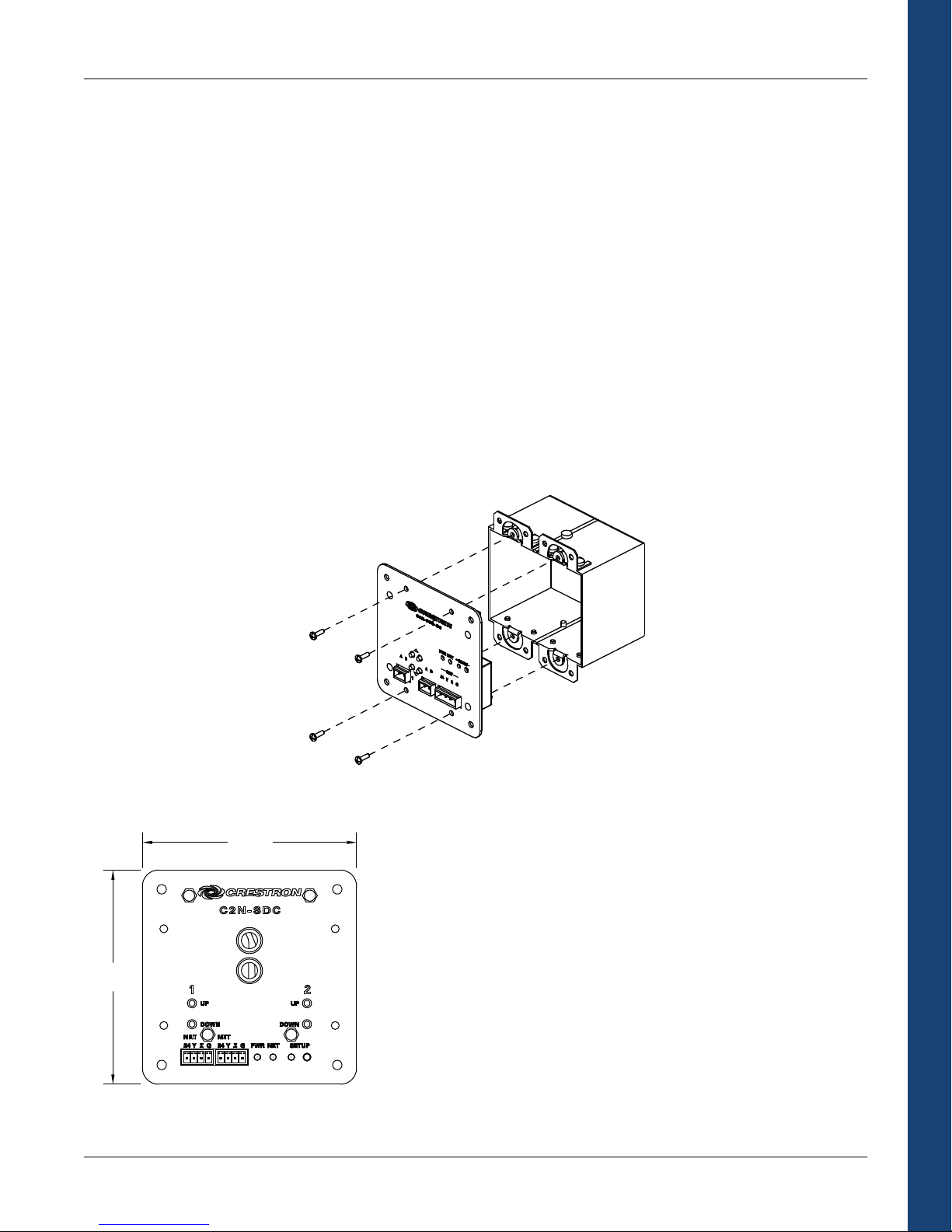
Crestron Commercial Lighting Design Guide
C2N--SDC
Shades
Shade and drape controllers are available to provide a convenient and cost-effective solution for harvesting natural light and controlling
the effects of the sun within an environment. By integrating shade and drape control into a Crestron system, natural light can be used to
help lower energy costs. In the colder months, shades can raise automatically to use sunlight as a supplemental heating source. During
the warmer months, shades can be programmed to block sunlight thereby reducing the call for cool air. In many cases motorized
shades offer simple convenience, such as reducing screen glare during multimedia presentations.
How We Control
Controllers are available as 24V DC, 120V AC, and 240V AC for controlling different motor types. There is also a Somfy® shade controller
that provides bidirectional serial control for up to two Somfy ILT Intelligent Shade Motors. The Somfy shade controller allows specific
positioning of the shades and polling of the current shade position for ultimate control.
How We Integrate
Shade and drape controllers integrate through Cresnet. Each motor output is independently controllable. The controllers are small
enough to hide in the wall, ceiling, or 2-gang electrical box. A DIN Rail controller is also available.
2-Gang Installation
4.1 in
(10.42 cm)
4.1 in
(10.42 cm)
Shades
The C2N-SDC is a 2-channel shade and drape controller designed to provide a
convenient and cost-effective solution for controlling a variety of motorized
window treatments as well as motorized doors, sunroofs, lifts and projection
screens.
The C2N-SDC is a Cresnet device with two independently controlled 120V AC
outputs. Each output provides up/down or open/close control of a conventional 3wire bidirectional type motor. Built-in timing and interlock logic make it easy to
program the C2N-SDC for fail-safe operation.
The C2N-SDC mounts in the wall or ceiling using an off-the-shelf 4" square or 2gang electrical box. Pushbuttons on the front of the unit allow for manual
operation of the motors during installation and setup.
63
Page 68

C2N--SDC--DC
C2N--SSC--2
DIN--2MC2
4.1 in
(10.42 cm)
4.1 in
(10.42 cm)
Crestron Commercial Lighting Design Guide
The C2N-SDC-DC is a 2-channel shade and drape controller designed to provide a
convenient and cost-effective solution for controlling 24V DC motorized shades
and drapes.
The C2N-SDC-DC is a Cresnet device with two independently controlled 24V DC
outputs, each designed to provide standard up/down or open/close control of a
conventional two-wire bidirectional type motor.
The C2N-SDC-DC mounts in the wall or ceiling using an off-the-shelf 4" square or
2-gang electrical box. Pushbuttons on the front of the unit allow for manual
operation of the motors during installation and setup.
Shades
2.14 in
(5.44 cm)
3.83 in
(9.73 cm)
The C2N-SSC-2 Somfy Shade Controller is a compact Cresnet device designed to
provide a bidirectional serial interface for up to two Somfy ILT Intelligent Shade
Motors. Window treatments equipped with the Somfy ILT motor offer enhanced
capability compared to typical 3-wire models.
In addition to basic open/close commands, the C2N-SSC-2 allows for setting each
shade to a specific position and polling for its current position with 16-bit
precision. Feedback signals provide confirmation of each motor's activity to
enable precise, predictable control, even from a remote location. Limit
adjustments are set electronically using buttons provided on the face of the unit,
and up to 20 presets for each output can be saved onboard the C2N-SSC-2 for
easy recall through the control system. The C2N-SSC-2 mounts discreetly to any
flat surface and requires a simple Cresnet connection to the control system.
The DIN-2MC2 is a 2-channel motor control module designed to provide control of
bidirectional motors for drapes, shades, projection screens, lifts, skylights, and
gates. Each channel supports up/down or open/close control of a conventional 3wire bidirectional type motor up to ½ HP. Built-in timing and interlock logic make
it easy to program the DIN-2MC2 for failsafe operation.
> Dual-channel bidirectional motor control
> Supports 120 to 240 volt 50/60 Hz
> Setup via front panel or software
> Mounts in a DIN rail cabinet or CAEN enclosure with adapter
64
Page 69

Crestron Commercial Lighting Design Guide
Accessories
Crestron Commercial Lighting Accessories
CEN-RFGW-EX infiNET EX Wireless Gateway
CLW-EXPEX infiNET EX Wireless Expander
DIN-AO8 DIN Rail Analog Out Interface
DIN-IO8 DIN Rail Versiport I/O Interface
DIN-HUB DIN Rail Cresnet Hub
DIN-BLOCK DIN Rail Cresnet Termination Block
DIN-PWS50 DIN Rail 50 Watt Cresnet Power Supply
CLX-PWS75 75 Watt Cresnet power supply module
GLA-PWS50 50 Watt Cresnet power supply module
GLA-BMS Building Management Systems Interface
GLA-DMX512 DMX Lighting Integration and Playback Processor
GLA-ESR Emergency Shunt Relay
GLA-PLS 3-Phase Power Loss Sensor
GLA-UPS Uninterruptable Power Supply
CEN-RFGW-EX
The CEN-RFGW-EX is a wireless gateway for up to 100 infiNET EX devices. It is
necessary when using infiNET EX products such as Cameo Wireless Dimmers
and Switches, Cameo Wireless Keypads, and wireless iLux products. The “Wi-Fi
friendly” gateway links into a Crestron control system through Cresnet or
Ethernet. Up to 16 wireless gateways can be installed in a single control
system. The CEN-RFGW-EX can be powered through either Cresnet or PoE
(Power over Ethernet).
For areas with dead spots, or to connect a wireless device that is more than
150 feet away from the nearest infiNET EX repeater, see the CLW-EXPEX below.
Each gateway supports up to five expanders.
Accessories
infiNET EX
Crestron’s infiNET EX technology provides ultra-reliable two-way wireless communications throughout a structure. Nearly every
device acts as a repeater, passing along the signal to any other device within range. As more devices are added, the system takes
advantage of redundant signal paths. infiNET EX runs on the 2.4 GHz spectrum, and has 16 possible channels to reduce
interference with other 2.4 GHz devices.
Range varies due to interference from walls and electronic noise, but it typically reaches 150 feet (46 m) indoors, 250 feet (76 m)
outdoors.
CLW-EXPEX
The CLW-EXPEX is a wireless expander designed to increase the range of
infiNET EX devices. The expander simply plugs into a standard AC wall socket –
all other setup is automatic. Use the expander to fill in dead spots in infiNET EX
coverage, or to extend the range up to 150 feet further per expander. Up to five
expanders can be used in a system.
65
Page 70

DIN-AO8
DIN-IO8
DIN-HUB
The DIN-AO8 is a DIN rail automation control module that provides eight analog output
ports for interfacing with third-party lighting and heating/cooling systems.
x Eight 0-10 V analog output control ports (maximum sink current 20mA per
x Interface for 3rd-party lighting and heating/cooling
x Programmable functionality via DIN-AP2
x Setup via front panel or software
Analog Outputs
Each analog output port provides a 0 to 10 Volt DC control signal ideally suited for
controlling 0-10 V lighting dimmers and heating/cooling valves. 10-bit resolution ensures
precise recall of lighting and climate control settings and smooth ramping between levels.
The DIN-IO8 is a DIN rail automation control module that provides eight Versiport I/O ports
for interfacing with a wide range of third-party devices and systems. Each Versiport can be
configured via software to function as a digital or analog sensing input or as a digital
trigger output.
x 8 Versiport I/O ports
x Interface for 3rd-party sensors, detectors, contact closures, and alarms
x Fully programmable functionality via DIN-AP2
Versiport
Accessories
Configured as a digital input, the Versiport senses a contact closure or logic level signal
from devices such as motion detectors, partition sensors, alarm panels, 12 V triggers, and
all types of switches and relays. As an analog input, the Versiport can sense changes in a
resistance or DC voltage level, working with everything from temperature and light sensors
to water level meters to volume control potentiometers. As a digital output, the Versiport
provides a logic level closure signal to trigger control and alarm inputs on a variety of
external devices.
The DIN-HUB is a DIN rail Cresnet hub designed to facilitate the configuration of large
Cresnet networks.
x 3-segment Cresnet hub
x 20 additional Cresnet devices per segment
3-Segment Cresnet Hub
Cresnet is the communications backbone for Crestron lighting modules, wall box dimmers,
shade controllers, thermostats, keypads, touchpanels, and many other devices. Cresnet
normally supports up to 20 Cresnet devices without requiring a hub. Adding a DIN-HUB
allows more devices. The DIN-HUB features three isolated Cresnet segments, each
supporting an additional 20 devices, allowing for systems of approximately 80 devices
total (including the "host" segment). More hubs may be added to allow up to a maximum
potential of 252 devices.
Crestron Commercial Lighting Design Guide
channel)
66
Page 71

Crestron Commercial Lighting Design Guide
DIN-BLOCK
DIN-PWS50
CLX-PWS75
GLA-PWS50
The DIN-BLOCK is a DIN rail Cresnet distribution block designed to facilitate the
termination of Cresnet wiring at a head end or distribution point.
x 12 port Cresnet distribution block
x Detachable screw terminal blocks for easy termination and troubleshooting
x Split power bus for flexible 24V power distribution
x Diagnostic LEDs for network power and data
x Passive device — no programming required
Cresnet Distribution
Cresnet is the communications backbone for Crestron lighting modules, wall box dimmers,
shade controllers, thermostats, keypads, touchpanels, and many other devices. Cresnet
allows for combinations of homerun and daisy chain wiring, and the DIN-BLOCK provides
a simple means for connecting up to 12 separate Cresnet cables as part of any sized
network.
The DIN-PWS50 is a 50 Watt Cresnet power supply module designed to snap onto a
standard DIN Rail installation. All wiring connections are made using screw terminals
positioned along the top and bottom, clearly accessible from the front for easy installation
and servicing. Three Cresnet power ports are provided.
x 50 Watt Cresnet power supply module
x Powers the DIN-AP2 Automation Processor and other Cresnet devices
x Includes 3 Cresnet power ports
x Cresnet data passes through unaffected
x Dual line power input terminals for easy daisy chaining
The CLX-PWS75 is a 75 Watt Cresnet power supply designed to mount in a CAEN
enclosure. A single CLX-PWS75 can be installed in any single-width enclosure, or up to two
may be installed side-by-side in a double-width enclosure. Four Cresnet power ports are
provided on the CLX-PWS75, which may be used to supply power directly to Cresnet
devices, or connect to the external power input ports of a PAC2 or PAC2M.
x 75 Watt Cresnet power supply module
x Occupies a single module space in a CAEN automation enclosure
x Provides supplemental power for systems with multiple keypads, touchpanels,
and other Cresnet devices
x Ideal for use with the PAC2 and PAC2M
The GLA-PWS50 is a 50 Watt Cresnet power supply designed for wall mounting. The GLAPWS50 mounts conveniently over a 4" square or 2-gang electrical box. All connections are
made inside the electrical box via flying leads using twist-on wire connectors. A partition is
included to isolate high voltage from Class 2 wiring within the box.
x 50 Watt Cresnet power supply
x Powers the IPAC and other Cresnet devices
x Provides backup power for Crestron Green Light cabinets
x Mounts to a 4" square or 2-gang electrical box
Accessories
67
Page 72

Crestron Commercial Lighting Design Guide
GLA-BMS
The GLA-BMS is an Ethernet based "protocol translator" which allows a Crestron system to communicate directly with any number of
building management protocols. Programmable like any other Crestron Ethernet device, the GLA-BMS makes it easy to interface with:
x BACnet/IP
x BACnet/MSTP (RS-485)
x Modbus TCP/IP
x Modbus RTU (RS-485)
x LonWorks
x Metasys N2 Open (Johnson Controls)
LIGHTING
TOUCHPANEL
GLA-DMX512
The GLA-DMX512 is a complete lighting playback and integration processor, featuring advanced DMX lighting control, sophisticated
event scripting, and robust I/O capabilities. The GLA-DMX512 is entirely web-based, which means no special software is needed to
operate or program the GLA-DMX512. Use a web browser on your computer or PDA to connect to the GLA-DMX512 to begin working
Accessories
with it.
After the GLA-DMX512 is programmed, the controller uses its built-in real-time clock/calendar, astronomical time functions, contact
closure inputs and wide variety of event triggers to interact with the outside world. Integrate the GLA-DMX512 with other external
devices via RS-232, Ethernet, or digital I/O ports for fully custom lighting and show control solutions.
x Seamlessly handles static scenes, cross fading and real-time
x Web-based operation and programming
x Powerful CueScript programming language
x Handles up to 4 independent timelines
x Locally program lighting scenes or snapshot from external
x Network multiple GLA-DMX512 units together to control a
x System integration via Ethernet, RS-232 and digital I/O ports
x 512 DMX inputs
x 512 DMX outputs
x 2000 cues
x 100 macros
x 500 time code event triggers
x 256 DMX input triggers
x Large on-board memory and removable xD memory card slot
x Rugged anodized extruded aluminum housing
x Removable "slide-in" flanges for surface mounting
Example GLA-BMS Application
CONTROL
SYSTEM
LANLAN
Color Key
BACnet
Ethernet
Cresnet
"streaming" DMX playback
X source
DM
large number of channels or devices
GLA-BMS
HVAC
FIRE
SYSTEM
DMX I nput
Ethernet
Output Card
Serial
I/O Expansion Port
xD Mem or y Ca rd
Link
Activity Power
DMX Out put
12VDC
DC Input
Input
68
Page 73

Crestron Commercial Lighting Design Guide
GLA-ESR
GLS-PLS
GLA-UPS
The GLA-ESR emergency bypass/shunt relay is designed for applications that require an
emergency load to be switched on during a loss of normal power. The GLA-ESR is available either
prepackaged in its own NEMA 1 enclosure or as a panel version to be installed inside an existing
enclosure. Models can be ordered with a two position closed/auto override test switch or with a
custom two position momentary on/auto override test switch. This switch can be used to verify
your emergency load is being switched properly during initial field wiring. UL 924 emergency
bypass/shunt relays will switch a lighting load upon loss of normal power downstream of an
emergency transfer switch, bypassing the wall switch position.
The GLS-PLS is a 3-phase power loss sensor designed for use with Crestron Green Light systems
to activate Override mode during a power failure. In response to a signal from the GLS-PLS, the
lighting system program can be temporarily overridden while designated emergency lighting
circuits are changed to their override preset levels and unnecessary lighting and other devices are
shut down to minimize the demand on emergency power equipment.
The GLS-PLS senses each leg of a 120 or 277 Volt 3-phase feed, providing LED indication of the
status of each phase on its front panel. When power is lost on any phase, the corresponding status
LED turns off and a contact closure is activated on each of two control outputs. Two isolated
control outputs are provided to allow for interfacing with third-party equipment in addition to the
Crestron lighting system. Each contact closure output is rated for 1A at 24 Volts DC.
Testing the GLS-PLS-120/277 is facilitated using three test switches located behind a small cover
plate on the front of the unit. Setting any switch to the TEST position simulates a loss of power on
the corresponding phase leg, providing a test of the unit's internal circuitry and any connected
equipment.
The steel enclosure is designed for mounting to a vertical surface. Conduit knockouts are provided
on the bottom, top, and both sides. All electrical connections are made via screw terminals
accessed by removing the front panel.
UL924
Underwriters Laboratories specifies safety standards for emergency lighting and power equipment
under UL924. The GLS-PLS power loss sensor will help satisfy UL924 requirements.
The GLA-UPS Uninterruptible Power Supply provides the highest level of protection for Crestron Green Light installations. It includes
reliable battery backup, surge protection and EMI/RFI line noise filtering. In the event of a power failure, the GLA-UPS includes an autorestart feature that eliminates the need to perform an on-site restart of the system. In addition, the GLA-UPS features a recycle/reset
button with sequential outlet start-up for proper system rebooting.
x 60-second delay-on AC outlet
x Battery backup, 1038 Joules of surge protection and EMI/RFI filtering
x 3 widely-spaced AC outlets Recycle/reset button with sequential outlet start-up
x IEC power input connector accepts included 6-inch power cord
x Diagnostic/Overload LEDs
x Resettable circuit breaker prevents dangerous system overloads
x Auto-restart capability eliminates the need to perform an on-site restart
x 550VA/300 Watts standby UPS system
Accessories
69
Page 74

Crestron Commercial Lighting Design Guide
Viridian
Integrated Energy Management Software
Viridian is a complete energy management program for an organization of any size. From a school to a whole enterprise, Viridian will
keep track of your carbon footprint while informing you of trends, usage, and ways to save money.
Viridian will monitor every light, shade, and HVAC system independently. The program generates reports showing energy consumption
throughout a day, week, month, or year. Information is displayed in easy to read charts and graphs. With Viridian, it is easy to keep
everything in check.
Every room can be monitored and managed from any touchpanel or web browser. View temperature, humidity, occupancy status, and
even CO
liveVIEW
Up to the minute details with graphic-rich liveVIEW show the vital statistics of your organization. Easy to read pie charts and bar graphs
pictorially describe the usage of all utilities (electric, gas, oil, water, etc.). Simply see where the energy is being consumed and take
action to reduce costs and gain efficiency.
Custom Reports
The data that is seen in liveVIEW is saved into the custom report database, enabling you to call upon an array of criteria to view
historical consumption. Compare utility bills to the liveVIEW report. Project accurate monthly energy costs over the course of a year.
Scheduling
Built into Viridian is the ability to schedule events around the building or enterprise. From simply turning lights on and off to preventing
water use during dry spells, Viridian provides the intelligence to help use resources wisely.
Viridian
Emergency Alerts
A watchful eye on your consumption, Viridian sends you alerts if it notices something out of the ordinary. From abnormal water or gas
volume, to excessive electrical current, to high CO
an alert.
Maintenance
Viridian can remember when lamps were last replaced and track the time of life for each lamp. As the end of life approaches a message
is sent out advising that the lamp should be replaced.
levels for a room, and then trigger a light scene or manually adjust HVAC accordingly.
2
TM
levels in the air, Viridian can prevent disaster by shutting down a system or sending
2
70
Page 75

Sample Screen Shots
Crestron Commercial Lighting Design Guide
Above is a liveVIEW window showing the total energy usage for
a building over one day. The green portion of the graph
represents energy produced by an on-site renewable energy
source. The gray area is energy provided by the power grid,
natural gas or other sources. Energy use is broken down by
area, usage type, and energy source type in the pie charts.
The monitor and control window allows a manager to access
each room across an organization. In this example, the
locations are divided by state, city, and building. After selecting
a location, the manager can view a floor plan, monitor the
status of a room, and make manual adjustments. Upcoming
and past events are shown at the bottom.
Above is an example report (in the PDF standard). This report
shows the energy usage for the ground floor of the building.
The current and average usage is listed for each room on the
ground floor. This data is also depicted in the pie chart.
Viridian
The scheduler window allows a manager to schedule recurring
events. This easy to use interface can set lights to turn on or
off at a specified time, change the room temperature set point,
and perform many other tasks automatically. It also can
schedule temporary overrides for special events.
71
Page 76
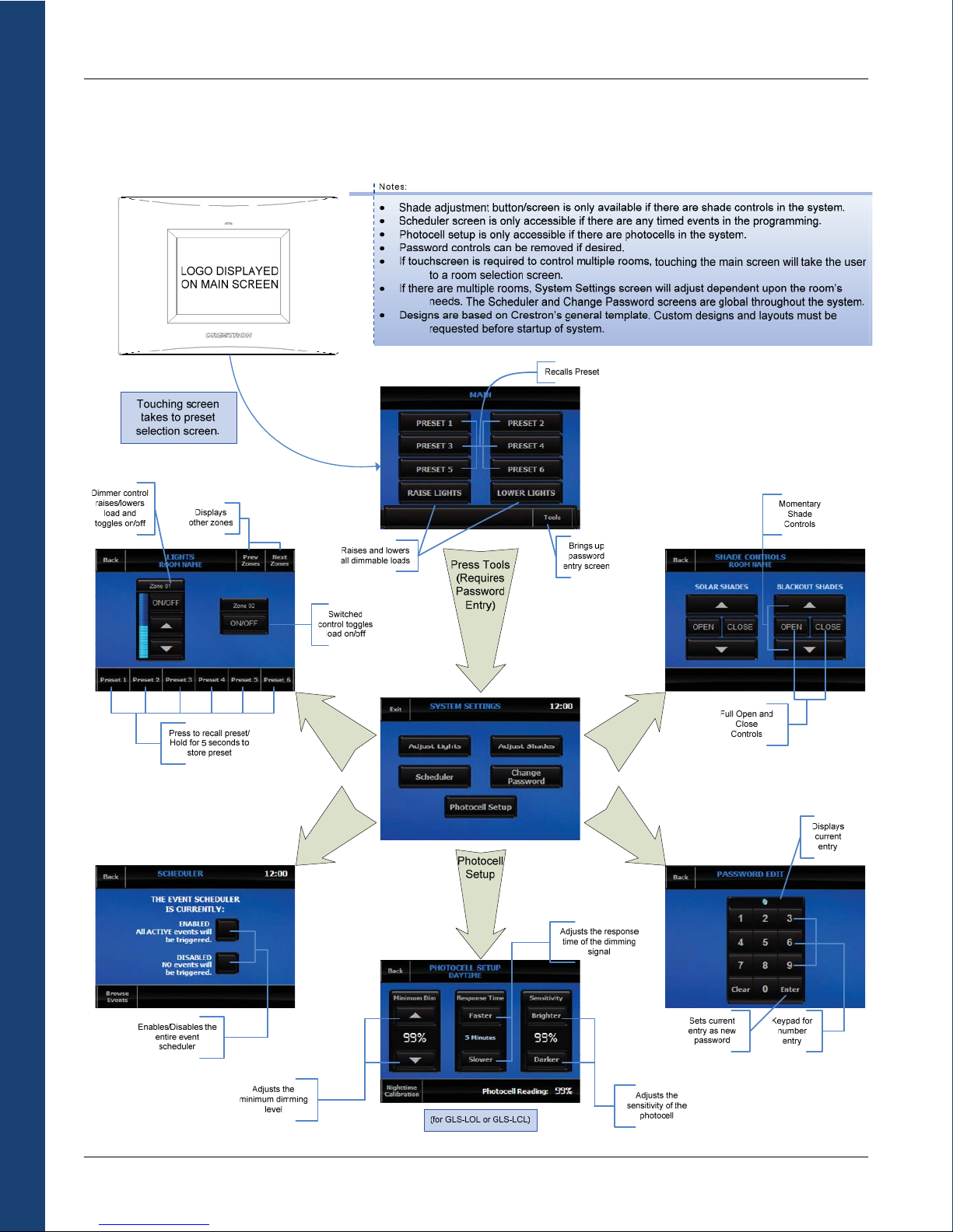
Appendix A - Touchpanel Graphics
A
d
j
L
u
i
g
h
t
s
Appendix A - Touchpanel Graphics
u
d
e
h
c
S
Crestron Commercial Lighting Design Guide
st
r
e
l
st
s
u
j
e
d
d
A
a
h
S
Ch
P
a
n
a
g
ss
e
w
o
r
d
72
Page 77
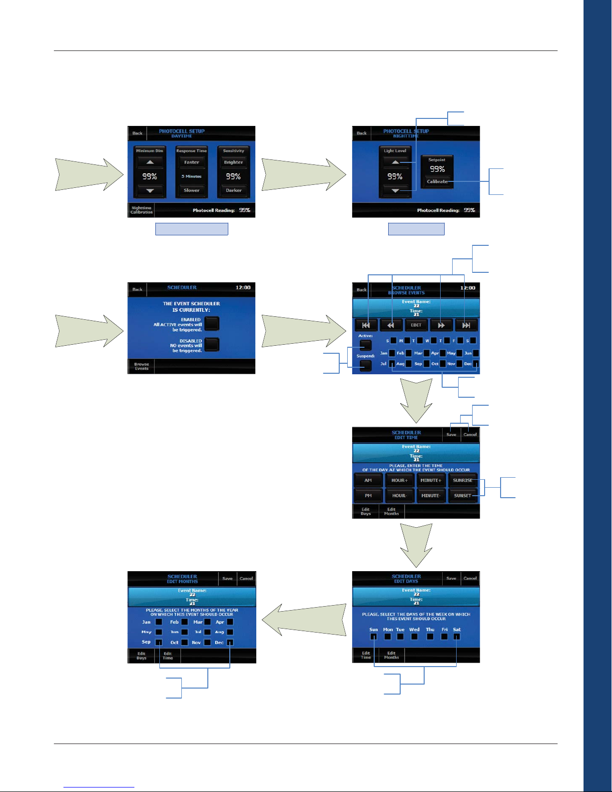
Crestron Commercial Lighting Design Guide
Adjusts the light level within the area/room
From Previous
Page
From Previous
Page
Nighttime Calibration
Browse Events
Enables/Disables the
currently displayed event
Stores the setpoint
for the nighttime
settings
(for GLS-LCL only)(for GLS-LOL or GLS-LCL)
Navigates through each
event in the system or
jumps to the first/last event
Appendix A – Touchpanel Graphics
Displays the days and months
Edit
the event will occur on
Saves the current changes or
cancels the current changes
Selects which months
the event will occur on
Edit Months
73
Selects which days the
event will occur on
Edit
Days
Edits the time the
event should occur at
Page 78

Crestron Commercial Lighting Design Guide
Appendix B - Common Keypad Layouts
All On
Presentation
Meeting
All Off
Shades Up
Shades Down
Conference Room Keypad Example 1
Cameo Keypad Model: C2N-CBD-TS
Scene 1 Scene 2
Scene 3 Scene 4
All On
All Off
Conference Room Keypad Example 2
Decorator Keypad Model: C2N-DB8
Raise
Lower
All On
All Off
Conference Room Keypad Example 3
Designer Keypad Model: CNX-B2
Appendix B – Common Keypad Layouts
All On
Breakfast
Lunch
Dinner Early
Dinner Late
All Off
Restaurant Keypad Example
Cameo Keypad Model: C2N-CBD-TS
Cameo Keypad Model C2N-CBD-TS
All On
Class
Presentation
All Off
Raise Screen
Lower Screen
Classroom Keypad Example
74
Lights On
Scene 1
Scene 2
Lights Off
FM
CD
AUX
MUTE
VOL
VOL
Keypad Example with A/V Integration
Designer Keypad Model: CNX-B12
Page 79

Crestron Commercial Lighting Design Guide
Appendix C - Glossary of Lighting Terms
A
AMPERE: The standard unit of measurement for electric current that
is equal to one coulomb per second. It defines the quantity of electrons
moving past a given point in a circuit during a specific period. It is
abbreviated as “amp” or “A”.
ANSI: Abbreviation for American National Standards Institute
ASHRAE: American Society of Heating, Refrigerating and Air-Conditioning
Engineers
B
BALLAST: A device used to operate fluorescent and HID lamps. The
ballast provides the necessary starting voltage, while limiting and
regulating the lamp current during operation
BALLAST CYCLING: Undesirable condition under which the ballast turns
lamps on and off (cycles) due to the overheating of the thermal switch
inside the ballast. This may be due to incorrect lamps, improper voltage
being supplied, high ambient temperature around the fixture, or the early
stage of ballast failure
BALLAST EFFICIENCY FACTOR: The ballast efficiency factor (BEF) is the
ballast factor (see below) divided by the input power of the ballast. The
higher the BEF (within the same lamp-ballast type), the more efficient
the ballast.
BALLAST FACTOR: The ballast factor (BF) for a specific lamp-ballast
combination represents the percentage of the rated lamp lumens that
will be produced by the combination
C
CANDELA: Unit of luminous intensity, describing the intensity of a light
source in a specific direction
CEC: Abbreviation for California Energy Commission
COMPACT FLUORESCENT: A small fluorescent lamp that is often used
as an alternative to incandescent lighting. The lamp life is about 10
times longer than incandescent lamps and is 3-4 times more efficacious.
Also called PL, Twin-Tube, CFL, or BIAX lamps
CONSTANT WATTAGE (CW) BALLAST: A premium type of HID ballast in
which the primary and secondary coils are isolated. It is considered a
high performance, high loss ballast featuring excellent output regulation
CONSTANT WATTAGE AUTOTRANSFORMER (CWA) BALLAST: A popular
type of HID ballast in which the primary and secondary coils are
electrically connected. Considered an appropriate balance between cost
and performance
D
DALI: Digital Addressable Lighting Interface is a protocol set out in the
technical standard IEC 60929. A DALI system is self-contained. A ballast
and a multi-sensor, offer benefits such as constant light control, PIR
movement-detection and IR remote operation. Multiple DALI systems
can be connected together using gateways to building management
systems. Software programs offer more sophisticated programming
functionality for grouped systems, such as scene setting, time clock, and
partition control
DAYLIGHT COMPENSATION: A dimming system controlled by a photocell
that reduces the output of the lamps when daylight is present. As
daylight levels increase, lamp intensity decreases. An energy-saving
technique used in areas with significant daylight contribution
DERATING: Components can be treated in such a way as to enhance
their life expectancy. Derating is the name normally given to operating a
component well inside its normal operating limits to extend the life of a
component, and is a practical means of reducing failures. The National
Electrical Code and local electrical codes determine the amount of
available current based on a derating factor. A derating factor improves
reliability by reducing the upper limit of current carrying capacity to
compensate for electrical, mechanical and thermal stress
DIN RAIL: A standardized 35 mm wide metal rail with hat-shaped cross
section. It is widely used for mounting circuit breakers and industrial
control equipment inside equipment racks.
DIRECT GLARE: Glare produced by a direct view of light sources. It is
often the result of insufficiently shielded light sources. (See GLARE)
DOWNLIGHT: A type of ceiling luminaire, usually fully recessed, where
most of the light is directed downward. May feature an open reflector
and/or shielding device
E
EFFICACY: A metric used to compare light output to energy consumption.
Efficacy is measured in lumens per watt. Efficacy is similar to efficiency,
but is expressed in dissimilar units. For example, if a 100-watt source
produces 9000 lumens, then the efficacy is 90 lumens per watt
ELECTROLUMINESCENT: A light source technology used in exit signs that
provides uniform brightness, long lamp life (approximately eight years),
while consuming very little energy (less than one watt per lamp)
ELECTRONIC BALLAST: Ballast that uses semi-conductor components to
increase the frequency of fluorescent lamp operation (typically in the 2040 kHz range. Smaller inductive components provide the lamp current
control. Fluorescent system efficiency is increased due to high frequency
lamp operation
ELECTRONIC DIMMING BALLAST: A variable output electronic fluorescent
ballast
ELECTRONIC LOW-VOLTAGE (ELV): Electronic low-voltage lighting uses
an electronic (solid-state technology) transformer to convert line voltage
(120 VAC) to low voltage (typically 12 VAC). This lower voltage is then
used power an incandescent low-voltage lamp. Track lights are usually
electronic low-voltage
ENERGY-SAVING BALLAST: A type of magnetic ballast designed so that
the components operate more efficiently, cooler and longer than
“standard magnetic" ballast. By US law, standard magnetic ballasts can
no longer be manufactured
F
FLUORESCENT LAMP: A light source consisting of a tube filled with
argon, along with krypton or other inert gas. When electrical current
is applied, the resulting arc emits ultraviolet radiation that excites the
phosphors inside the lamp wall, causing them to radiate visible light
Appendix C – Glossary of Lighting Terms
75
Page 80

Crestron Commercial Lighting Design Guide
Appendix C – Glossary of Lighting Terms
FOOT CANDLE (FC): The English unit of measurement of the illuminance
(or light level) on a surface. One foot candle is equal to one lumen per
square foot
FORWARD PHASE DIMMING: Rather than attempting to restrict the
amplitude of the current flowing through a lamp, as in other forms of
dimming, forward phase control works by switching off the beginning
part of each cycle of the alternating current supply
FOUR-WIRE 10V ANALOG SIGNAL DIMMING: Two power wires (switched
hot and neutral) and two additional control wires that are connected to a
low-voltage circuit. Note: these ballasts do not turn on and off like DALI
ballasts, so in addition to the low-voltage-level control circuit, they must
also have a line-voltage switch. Zero to ten-volt control is a low-voltage
DC dimming method. Power wires are rated Class 1 and control wires
are rated Class 2. This separation allows multiple circuits to use the
same dimming signal without additional power equipment
G
GLARE: The effect of brightness or differences in brightness within the
visual field sufficiently high to cause annoyance, discomfort or loss of
visual performance
H
HALOGEN: (SEE TUNGSTEN HALOGEN LAMP)
HARMONIC DISTORTION: A harmonic is a sinusoidal component of a
periodic wave having a frequency that is a multiple of the fundamental
frequency. Harmonic distortion from lighting equipment can interfere
with other appliances and the operation of electric power networks. The
total harmonic distortion (THD) is usually expressed as a percentage of
the fundamental line current. THD for 4-foot fluorescent ballasts usually
range from 20% to 40%. For compact fluorescent ballasts, THD levels
greater than 50% are not uncommon
HID: Abbreviation for high intensity discharge. Generic term describing
mercury vapor, metal halide, high-pressure sodium, and (informally)
low-pressure sodium light sources and luminaires
HIGH BAY: Pertains to the type of lighting in an industrial application
where the ceiling is 20 feet or higher. Also describes the application
itself
HIGH OUTPUT (HO): A lamp or ballast designed to operate at higher
currents (800 mA) and produce more light.
HIGH POWER FACTOR: Ballast with a 0.9 or higher rated power factor,
which is achieved by using a capacitor.
HIGH PRESSURE SODIUM LAMP: A high intensity discharge (HID) lamp
whose light is produced by radiation from sodium vapor (and mercury)
HOT RESTART or HOT RESTRIKE: The phenomenon of re-striking the arc
in an HID light source after a momentary power loss. Hot restart occurs
when the arc tube has cooled a sufficient amount
I
IESNA: Abbreviation for Illuminating Engineering Society of North
America.
ILLUMINANCE: A photometric term that quantifies light incident on a
surface or plane. Illuminance is commonly called light level. It is
expressed as lumens per square foot (foot candles), or lumens per
square meter (lux)
INDIRECT GLARE: Glare produced from a reflective surface.
INSTANT START: A fluorescent circuit that ignites the lamp instantly with
a very high starting voltage from the ballast. Instant start lamps have
single-pin bases
L
LAMP CURRENT CREST FACTOR (LCCF): The peak lamp current divided
by the RMS (average) lamp current. Lamp manufacturers require <1.7
for best lamp life. An LCCF of 1.414 is a perfect sine wave
LAMP LUMEN DEPRECIATION FACTOR (LLDF): A factor that represents
the reduction of lumen output over time. The factor is commonly used as
a multiplier to the initial lumen rating in illumination calculations, which
compensates for the lumen depreciation. The LLD factor is a
dimensionless value between 0 and 1
LAY-IN-TROFFER: A fluorescent fixture; usually a 2' x 4' fixture that sets
or "lays" into a specific ceiling grid
LED: Abbreviation for light emitting diode. Consumes low wattage and
has a rated life of greater than 80 years. Increasingly popular as
production costs are decreasing.
LENS: Transparent or translucent medium that alters the directional
characteristics of light passing through it. Usually made of glass or
acrylic
LIGHT LOSS FACTOR (LLF): Factors that allow for a lighting system's
operation at less than initial conditions. These factors are used to
calculate maintained light levels. LLFs are divided into two categories,
recoverable and non-recoverable. Examples are lamp lumen
depreciation and luminaire surface depreciation
LIFE-CYCLE COST: The total costs associated with purchasing,
operating, and maintaining a system over the life of that system
LOUVER: Grid type of optical assembly used to control light distribution
from a fixture. Can range from small-cell plastic to the large-cell
anodized aluminum louvers used in parabolic fluorescent fixtures
LOW POWER FACTOR: Essentially, an uncorrected ballast power factor of
less than 0.9 (SEE NPF)
LOW-PRESSURE SODIUM: A low-pressure discharge lamp in which light
is produced by radiation from sodium vapor. Considered a
monochromatic light source (most colors are rendered as gray)
LOW-VOLTAGE LAMP: A lamp (typically compact halogen) that provides
both intensity and good color rendition. Lamp operates at 12V and
requires the use of a transformer. Common lamps are MR11, MR16, and
PAR36
LOW-VOLTAGE SWITCH: A relay (magnetically-operated switch) that
allows local and remote control of lights, including centralized time clock
or computer control
LUMEN: A unit of light flow, or luminous flux. The lumen rating of a lamp
is a measure of the total light output of the lamp
LUMINAIRE: A complete lighting unit consisting of a lamp or lamps, along
with the parts designed to distribute the light, hold the lamps, and
connect the lamps to a power source. Also called a fixture
LUMINAIRE EFFICIENCY: The ratio of total lumen output of a luminaire
and the lumen output of the lamps, expressed as a percentage. For
example, if two luminaires use the same lamps, more light will be
emitted from the fixture with the higher efficiency.
76
Page 81

Crestron Commercial Lighting Design Guide
LUMINANCE: A photometric term that quantifies brightness of a light
source or of an illuminated surface that reflects light. It is expressed as
foot lamberts (English units) or candelas per square meter (Metric units)
LUX (LX): The metric unit of measure for illuminance of a surface. One
lux is equal to one lumen per square meter. One lux equals 0.093 foot
candles
M
MAINTAINED ILLUMINANCE: Refers to light levels of a space at other
than initial or rated conditions. This term considers light loss factors
such as lamp lumen depreciation, luminaire dirt depreciation, and room
surface dirt depreciation
MAGNETIC LOW-VOLTAGE (MLV): Magnetic low-voltage lighting uses a
magnetic (core and coil technology) transformer to convert line voltage
(120 VAC) to low voltage (typically 12 VAC). This lower voltage is then
used to power an incandescent low-voltage lamp. Recessed lights are
most often magnetic low-voltage. Magnetic low-voltage lights tend to be
larger and heavier than electronic low-voltage
MERCURY VAPOR LAMP: A type of high intensity discharge (HID) lamp in
which most of the light is produced by radiation from mercury vapor.
Emits a blue-green cast of light. Available in clear and phosphor-coated
lamps
METAL HALIDE: A type of high intensity discharge (HID) lamp in which
most of the light is produced by radiation of metal halide and mercury
vapors in the arc tube. Available in clear and phosphor-coated lamps
MR-16: A low-voltage quartz reflector lamp, only 2" in diameter.
Typically the lamp and reflector is one unit, which directs a sharp,
precise beam of light
N
NADIR: A reference direction directly below a luminaire, or "straight
down"
NEMA: Abbreviation for National Electrical Manufacturers Association
NEON/COLD CATHODE: Highly inductive boost transformer for neon/cold
cathode lighting
NIST: Abbreviation for National Institute of Standards and Technology
NPF (NORMAL POWER FACTOR): A ballast/lamp combination in which no
components (e.g., capacitors) have been added to correct the power
factor, making it normal (essentially low, typically 0.5 or 50%)
O
OCCUPANCY SENSOR: Control device that turns lights off after the space
becomes unoccupied. May be ultrasonic, infrared or other type
OPTICS: A term referring to the components of a light fixture (such as
reflectors, refractors, lenses, louvers) or to the light emitting or lightcontrolling performance of a fixture
P
PARABOLIC LUMINAIRE: A popular type of fluorescent fixture that has a
louver composed of aluminum baffles curved in a parabolic shape. The
resultant light distribution produced by this shape provides reduced
glare, better light control, and is considered to have greater aesthetic
appeal
PARACUBE: A metallic coated plastic louver made up of small squares.
Often used to replace the lens in an installed troffer to enhance its
appearance. The paracube is visually comfortable, but the luminaire
efficiency is lowered. Also used in rooms with computer screens
because of their glare-reducing qualities
PHOTOCELL: A light sensing device used to control luminaires and
dimmers in response to detected light levels
PHOTOMETRIC REPORT: A photometric report is a set of printed data
describing the light distribution, efficiency, and zonal lumen output of a
luminaire. This report is generated from laboratory testing
POWER FACTOR: The ratio of the AC Volts x Amps through a device to
the AC wattage of the device. A device such as a ballast that measures
120 Volts, 1 Amp, and 60 Watts has a power factor of 50% (Volts x Amps
= 120 VA, therefore 60 Watts/120 VA = 0.5). Some utilities charge
customers for low power factor systems
PREHEAT: A type of ballast/lamp circuit that uses a separate starter to
heat up a fluorescent lamp before high voltage is applied to start the
lamp
Q
QUAD-TUBE LAMP: A compact fluorescent lamp with a double twin tube
configuration
R
RADIO FREQUENCY INTERFERENCE (RFI): Interference to the radio
frequency band caused by other high frequency equipment or devices in
the immediate area. Fluorescent lighting systems generate RFI
RAPID START (RS): The most popular fluorescent lamp/ballast
combination used today. This ballast quickly and efficiently preheats
lamp cathodes to start the lamp. Uses a "bi-pin" base
ROOM CAVITY RATIO (RCR): A ratio of room dimensions used to quantify
how light will interact with room surfaces. A factor used in illuminance
calculations
REFLECTANCE: The ratio of light reflected from a surface to the light
incident on the surface. Reflectances are often used for lighting
calculations. The reflectance of a dark carpet is around 20%, and a
clean white wall is roughly 50% to 60%
REFLECTOR: The part of a light fixture that shrouds the lamps and
redirects some light emitted from the lamp
REFRACTOR: A device used to redirect the light output from a source,
primarily by bending the waves of light.
RECESSED: The term used to describe the doorframe of a troffer where
the lens or louver lies above the surface of the ceiling.
REGULATION: The ability of a ballast to hold constant (or nearly constant)
the output watts (light output) during fluctuations in the voltage feeding
of the ballast. Normally specified as +/- percent change in output
compared to +/- percent change in input.
RELAY: A device that switches an electrical load on or off based on small
changes in current or voltage. Examples: low voltage relay and solid
state relay
RETROFIT: Refers to upgrading a fixture, room, or building by installing
new parts or equipment
REVERSE PHASE DIMMING: Rather than attempting to restrict the
amplitude of the current flowing through a lamp, as in other forms of
dimming, reverse phase control works by switching off the end part of
each cycle of the alternating current supply
Appendix C – Glossary of Lighting Terms
77
Page 82

Crestron Commercial Lighting Design Guide
Appendix C – Glossary of Lighting Terms
S
SELF-LUMINOUS EXIT SIGN: An illumination technology using phosphorcoated glass tubes filled with radioactive tritium gas. The exit sign uses
no electricity and thus does not need to be hardwired
SEMI-SPECULAR: Term describing the light reflection characteristics of a
material. Some light is reflected directionally, with some amount of
scatter
SHIELDING ANGLE: The angle measured from the ceiling plane to the line
of sight where the bare lamp in a luminaire becomes visible. Higher
shielding angles reduce direct glare. It is the complementary angle of the
cutoff angle.
SPACING CRITERION: A maximum distance that interior fixtures may be
spaced that ensures uniform illumination on the work plane. The
luminaire height above the work plane multiplied by the spacing criterion
equals the center-to-center luminaire spacing
SPECULAR: Mirrored or polished surface. The angle of reflection is equal
to the angle of incidence. This word describes the finish of the material
used in some louvers and reflectors
STARTER: A device used with a ballast to start (preheat) fluorescent
lamps
STROBOSCOPIC EFFECT: Condition where rotating machinery or other
rapidly moving objects appear to be standing still due to the alternating
current supplied to light sources. Sometimes called "strobe effect."
T
T12 LAMP: Industry standard for a fluorescent lamp that is 12 oneeighths, one inch in diameter. Other sizes are T10 and T8 lamps
TANDEM WIRING: A wiring option in which a single ballast is shared by
two or more luminaires. This reduces labor, materials, and energy costs.
Also called "master-slave" wiring.
THERMAL FACTOR: A factor used in lighting calculations that
compensates for the change in light output of a fluorescent lamp due to
a change in bulb wall temperature. It is applied when the lamp-ballast
combination under consideration is different from that used in the
photometric tests.
THREE-WIRE ANALOG POWER DIMMING: Three-wire control is a linevoltage phase-control dimming method. Along with Hot and Neutral, the
dimming signal is communicated via a third wire called Dimmed Hot. All
three wires are rated Class 1 and can be run within the same conduit.
TRIGGER START: Type of ballast commonly used with 15-watt and 20watt straight fluorescent lamps
TROFFER: The term used to refer to a recessed fluorescent light fixture
(combination of trough and coffer)
TUNGSTEN HALOGEN LAMP: A gas-filled tungsten filament incandescent
lamp with a lamp envelope made of quartz to withstand the high
temperature. This lamp contains some halogens (namely iodine,
chlorine, bromine, and fluorine), which slow the evaporation of the
tungsten. Also, commonly called a quartz lamp
TWIN-TUBE: (SEE COMPACT FLUORESCENT)
TWO-WIRE ANALOG POWER DIMMING: Two-wire is a line-voltage phasecontrol dimming method. The ballast receives the dimming signal
through the Dimmed Hot wire. Intended for small-scale retrofit
applications, the two-wire control method is often the easiest way to
implement dimming in existing fluorescent fixtures
U
ULTRA VIOLET (UV): Invisible radiation that is shorter in wavelength and
higher in frequency than visible violet light (literally beyond the violet
light)
UNDERWRITERS' LABORATORIES (UL): An independent organization
whose responsibilities include rigorous testing of electrical products.
When products pass these tests, they can be labeled (and advertised) as
"UL listed." UL tests for product safety only
V
VANDAL-RESISTANT: Fixtures with rugged housings, break-resistant
type shielding, and tamper-proof screws
VCP: Abbreviation for visual comfort probability. VCP is a rating system
for evaluating direct discomfort glare. This method is a subjective
evaluation of visual comfort expressed as the percent of occupants of a
space who will be bothered by direct glare. VCP allows for several
factors: luminaire luminances at different angles of view, luminaire size,
room size, luminaire mounting height, illuminance, and room surface
reflectivity. VCP tables are often provided as part of photometric reports
VERY HIGH OUTPUT (VHO): A fluorescent lamp that operates at a "very
high" current (1500 mA), producing more light output than a "high
output" lamp (800 mA) or standard output lamp (430 mA)
VA (VOLT-AMPERE): The amount of apparent power in an electrical
circuit. A volt-ampere and a watt are nearly identical for resistive loads,
such as an incandescent lamp. For devices with a power factor less than
one, such as a fluorescent bulb, the volt-ampere rating is higher than the
real power (in watts) consumed by the load.
VOLT: The standard unit of measurement for electrical potential. It
defines the "force" or "pressure" of electricity
VOLTAGE: The difference in electrical potential between two points of an
electrical circuit
W
WALLWASHER: Describes luminaires that illuminate vertical surfaces.
WATT (W): The unit for measuring electrical power. It defines the rate of
energy consumption by an electrical device when it is in operation. The
energy cost of operating an electrical device is calculated as its wattage
times the hours of use. In single-phase circuits, it is related to volts and
amps by the formula: Volts x Amps x PF = Watts. (Note: For AC circuits,
PF must be included.)
WORK PLANE: The level at which work is done and at which illuminance
is specified and measured. For office applications, this is typically a
horizontal plane 30 inches above the floor (desk height)
78
Page 83

Page 84

Crestron Electronics, Inc.
15 Volvo Drive, Rockleigh, NJ 07647
Tel: 800.237.2041 | 201.767.3400 | Fax: 201.767.1903
www.crestron.com
Printed in USA
Doc. 4775A
07/2010
Specifications subject to change without notice
 Loading...