

Page 1

DM-PSU-ULTRA-MIDSPAN
DigitalMedia™ Ultra Midspan PoDM++ Injector
Installation Guide
Description
The DM-PSU-ULTRA-MIDSPAN provides two PoDM++ power sourcing equipment (PSE)
ports designed to power DM 8G+
the DM-PSU-ULTRA-MIDSPAN can supply up to 45 watts of power to a PoDM++,
PoDM+, or PoDM powered device. (Due to the inherent power loss over CATx cable, a
maximum of 40 watts is delivered to the powered device.)
The DM-PSU-ULTRA-MIDSPAN can simultaneously power a DM 8G+ transmitter and
receiver in a standalone conguration while passing data between the two devices.
DM-PSU-ULTRA-MIDSPAN
The
(for example, a TS-1542-C).
NOTE: The DM-PSU-ULTRA-MIDSPAN supplies power to a connected device only if
the device requests power. As a result, the DM-PSU-ULTRA-MIDSPAN can be
connected to the PSE port of a device that does not require power from the
DM-PSU-ULTRA-MIDSPAN (for example, a DMPS3-4K-150-C).
NOTE: The DM-PSU-ULTRA-MIDSPAN is compatible with HDBaseT Alliance
specications and can be used to supply up to 30 watts of power to IEEE 802.3at
compliant HDBaseT
®
devices. (Due to the inherent power loss over CATx cable, a
maximum of 25.5 watts is delivered to the HDBaseT PoE+ or PoE powered device.)
®
PoDM powered devices (PDs). Each PoDM++ port of
can also power a touch screen that has a DM 8G+ input
Additional Resources
Visit the product page on the Crestron website (www.crestron.com)
for additional information and the latest rmware updates. Use a QR
reader application on your mobile device to scan the QR image.
Connection to DM-TX-4K-302-C Transmitter and DM-RMC-4K-SCALER-C-DSP Receiver
DM-PSU-ULTRA-MIDSPAN
DM-TX-4K-302-C,
side panel
DM-RMC-4K-SCALER-C-DSP,
side panel
Mounting
The DM-PSU-ULTRA-MIDSPAN can be mounted into a rack, onto a rack rail, or under a
table:
• To mount the DM-PSU-ULTRA-MIDSPAN into a rack, use the Crestron
®
ST-RMK
Rack Mount Kit (sold separately).
• To mount the DM-PSU-ULTRA-MIDSPAN onto a rack rail, use two mounting screws
(not included).
• To mount the DM-PSU-ULTRA-MIDSPAN to the underside of a table, use four
#12 x 5/8-inch mounting screws (not included).
Hardware Hookup
Connect the DM-PSU-ULTRA-MIDSPAN as required for the application.
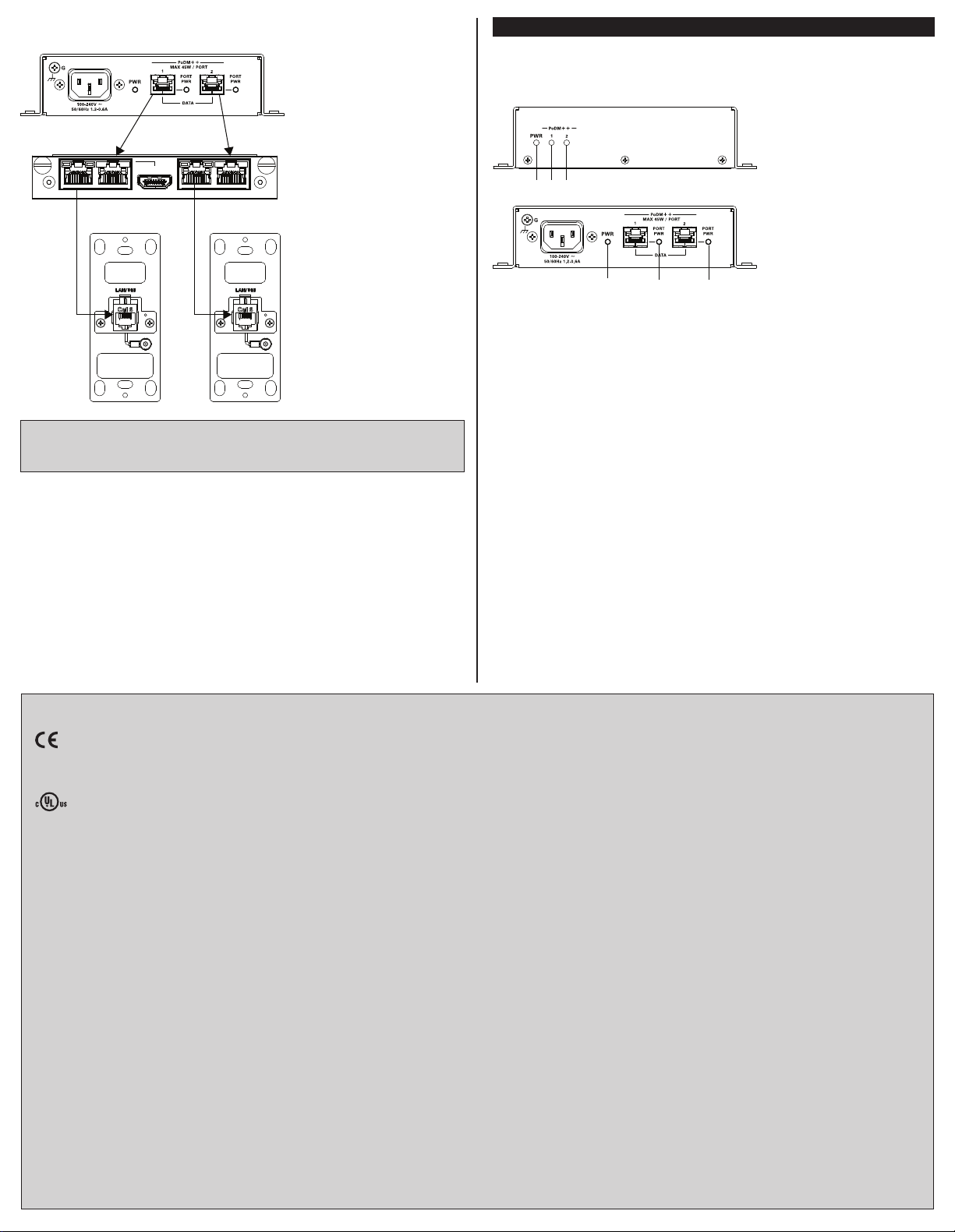
Hardware Hookup
From ac power
source
To PoDM++
powered device
1
The PoDM++ PSE ports are also compatible with PoDM+, PoDM, HDBaseT PoE+, and HDBaseT PoE
powered devices.
2
Any wiring that is connected to a PoDM++ PSE port is for intrabuilding use only and should not be connected
to a line that runs outside of the building in which the PSE is located.
Refer to the following illustrations for sample connection diagrams.
To PoDM++
1, 2
powered device
1, 2
Connection to DMPS3-4K-150-C and DM-RMC-4K-SCALER-DSP
DMPS3-4K-150-C, rear panel
DM-PSU-ULTRA-MIDSPAN
DM-RMC-4K-SCALER-C-DSP,
side panel
3
4
2
Page 2
Connection to DMC-4K-CO-HD Card for Powering TS-1542-C Touch Screen
DM-PSU-ULTRA-MIDSPAN
DMC-4K-CO-HD
HDMI
DM OUT POE IN DMC-4K-CO-HD DM OUT POE IN
TS-1542-IMCWTS-1542-IMCW
LED Indicators
LED indicators are provided on the front and rear panels of the
DM-PSU-ULTRA-MIDSPAN.
LED Indicators
Front panel
Rear panel
NOTE: The illustration above shows connection of the DMC-4K-CO-HD card to the
TS-1542-IMCW. The DMC-4K-CO-HD card can also connect directly to the DM 8G+
input of the TS-1542-C touch screen.
As of the date of manufacture, the DM-PSU-ULTRA-MIDSPAN has been tested and found to comply
with specications for CE marking.
This product is Listed to applicable UL Standards and requirements by Underwriters Laboratories Inc.
Ce produit est homologué selon les normes et les exigences UL applicables par Underwriters
Laboratories Inc.
This unit is for in-house use only, not for outside of building.
Cet appareil est destiné pour utilisation dans la maison seulement, pas pour l’extérieur du bâtiment.
Mechanical Loading: Mounting of the equipment in the rack should be such that a hazardous
condition is not achieved due to uneven mechanical loading.
Chargement Mécanique: Montage d’équipement dans le rack doit être telle qu’une situation
dangereuse n’est pas lié a cause d’un chargement mécanique irrégulier.
Federal Communications Commission (FCC) Compliance Statement
This device complies with part 15 of the FCC Rules. Operation is subject to the following conditions:
(1) This device may not cause harmful interference and (2) this device must accept any interference
received, including interference that may cause undesired operation.
CAUTION: Changes or modications not expressly approved by the manufacturer responsible for
compliance could void the user’s authority to operate the equipment.
NOTE: This equipment has been tested and found to comply with the limits for a Class B digital
device, pursuant to part 15 of the FCC Rules. These limits are designed to provide reasonable
protection against harmful interference in a residential installation. This equipment generates, uses
and can radiate radio frequency energy and, if not installed and used in accordance with the
instructions, may cause harmful interference to radio communications. However, there is no guarantee
that interference will not occur in a particular installation. If this equipment does cause harmful
interference to radio or television reception, which can be determined by turning the equipment off
and on, the user is encouraged to try to correct the interference by one or more of the following
measures:
• Reorient or relocate the receiving antenna.
• Increase the separation between the equipment and receiver.
• Connect the equipment into an outlet on a circuit different from that to which the receiver is
connected.
• Consult the dealer or an experienced radio/TV technician for help.
Industry Canada (IC) Compliance (IC) Compliance Statement
Industrie Canada (IC) Déclaration de conformité
CAN ICES-3(B)/NMB-3(B)
PWR: Lights green to indicate that the DM-PSU-ULTRA-MIDSPAN is receiving mains
ac power
PoDM++ 1 PORT PWR: Lights green to indicate that port 1 is delivering power to the
connected device
PoDM++ 2 PORT PWR: Lights green to indicate that port 2 is delivering power to the
connected device
The product warranty can be found at www.crestron.com/warranty.
The specic patents that cover Crestron products are listed at patents.crestron.com.
Certain Crestron products contain open source software. For specic information, please visit
www.crestron.com/opensource.
Crestron, the Crestron logo, DigitalMedia, and DM 8G+ are either trademarks or registered trademarks
of Crestron Electronics, Inc. in the United States and/or other countries. HDBaseT is either a
trademark or registered trademark of the HDBaseT Alliance in the United States and/or other
countries. UL and the UL logo are either trademarks or registered trademarks of Underwriters
Laboratories, Inc. in the United States and/or other countries. Other trademarks, registered
trademarks, and trade names may be used in this document to refer to either the entities claiming the
marks and names or their products. Crestron disclaims any proprietary interest in the marks and
names of others. Crestron is not responsible for errors in typography or photography.
This document was written by the Technical Publications department at Crestron.
©2016 Crestron Electronics, Inc.
Crestron Electronics, Inc. Installation Guide - DOC. 7848B
15 Volvo Drive Rockleigh, NJ 07647 (2047018)
Tel: 888.CRESTRON 10.16
Fax: 201.767.7576 Specications subject to
www.crestron.com change without notice.
 Loading...