

Crestron DM-PSU-8-PLUS, DM-PSU-16-PLUS Do Manual
DO GUIDE
or to HDBaseT device
DM-PSU-8-PLUS/DM-PSU-16-PLUS
®
8-Port/16-Port PoDM+ Power Supply for DM 8G+
I/O Cards
DO Install the Device
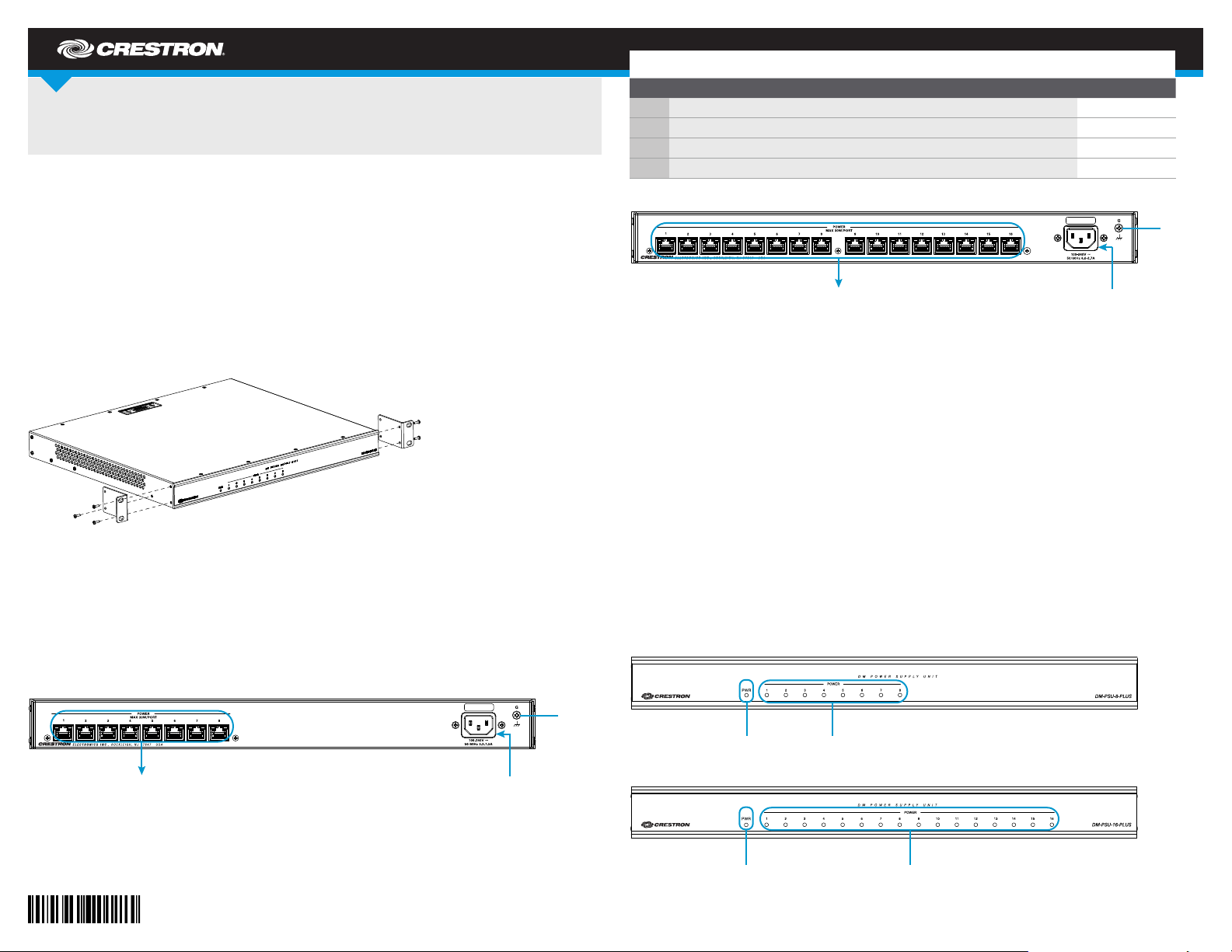
The Crestron® DM-PSU-8-PLUS and DM-PSU-16-PLUS can be mounted into a rack or placed onto a
at surface.
NOTE: The DM-PSU-8-PLUS and DM-PSU-16-PLUS do not require rmware updates.
Mount into a Rack
The DM-PSU-8-PLUS and DM-PSU-16-PLUS each occupy 1U of rack space. Using a #1 Phillips
screwdriver, attach the two included rack ears to the device using the six included 4-40 x 3/8”
Phillips pan head screws. Then, mount the device into the rack using four mounting screws
(not included).
Rack Ear Attachment
DO Check the Box
QTY ITEM PART NUM.
2 Bracket, Rack Ear, 1U 20 43941
4 Foot, 0.5" x 0.5" x 0.23", Rubber 2002389
1 Power Cord, 6' 7" (2 m) 4505164
6 Screw, 4-40 x 3/8", Pan Head, Phillips 20 0 7170
DM-P SU-16-PLUS Rear Panel Connections
Ground
POWER
MAX 30W/PORT 1–16:
To POE IN port of DMC Series
DM 8G+ I/O card
NOTE: Ensure that the device is properly grounded by connecting the chassis ground lug to
an earth ground circuit (for example, building steel).
NOTE: The 8 POWER ports of the DM-PSU-8-PLUS and the 16 POWER ports of the
DM-PSU-16-PLUS are PoDM+ and HDBaseT® PoE+ power sourcing equipment ports (PSEs).
Each port supports one PoDM, PoDM+, HDBaseT PoE, or HDBaseT PoE+ powered device.
Cabling that connects to a PoDM+ or HDBaseT PoE+ PSE port is designed for intrabuilding use only.
100–240V~50/60 Hz
6.6–2.7A:
From ac power outlet
Place onto a Flat Surface
When placing the device onto a at surface or stacking it with other equipment, attach the included
feet near the corners on the underside of the device.
DO Connect the Device
Connect the device as required for the application.
DM-P SU-8-PL US Rear Panel Connections
Ground
POWER
MAX 30W/PORT 1–8:
To POE IN port of DMC Series
or to HDBaseT
DM 8G+
®
I/O card
®
device
100–240V~50/60 Hz
3.3–1.5A:
From ac power outlet
DO Identify the LEDs
PWR: Lights green to indicate that the DM-PSU-8-PLUS or DM-PSU-16-PLUS is receiving
ac power
POWER 1- 8 or 1-16 : Light green to indicate that PoDM, PoDM+, HDBaseT PoE, or HDBaseT
PoE+ is supplying power to a compatible device that is connected to the corresponding port via
a DMC Series I/O card
DM-P SU-8-PL US Front Panel LEDs
DM-P SU-16-PLUS Front Panel LEDs
DO Learn More
Visit the website for additional information and the latest rmware
updates. To learn more about this product, use a QR reader
application on your mobile device to scan the QR image.
Crestron Electronics
15 Volvo Drive, Rockleigh, NJ 07647
888.CRESTRON | www.crestron.com
DM-PSU-8-PLUS DM-PSU-16-PLUS
As of the date of manufacture, the product has been tested and found to comply with spe cications for CE mar king.
This product is Listed to applicable UL® Standards an d requirements tested by Under writers La boratories Inc.
Ce produit est homologué selon les normes et les exigences U L applicable s par Und erwriters Laboratories Inc.
Federal Communications Commission (FCC) Compliance Statement
This device com plies with par t 15 of the FCC Rules. Op eration is subject to the followi ng two co nditio ns:
(1) This devic e may not cause harmful in terference, and (2) this device must ac cept any interference rece ived, including inter ference
that may cause undesired operation.
CAUTION: Changes or modication s not expr essly approve d by the manufact urer re spons ible for compli ance could void the
user’s authority to operate the equipment.
NOTE: This equipm ent has been tested and found to co mply wi th the limits for a Cl ass B digital device, pu rsuant to par t 15 of the
FCC Rules. Thes e limits are designed to p rovide reason able pr otection agai nst har mful interfe rence in a residentia l insta llation.
This equipment generates, u ses and can radiate radio frequency energy a nd, if not installed and u sed in ac cordance with the
instruction s, may cause har mful interfe rence to radio communi cations. Howeve r, there is no guaran tee that i nterference will not
occur in a particular installation.
If this equipment does c ause ha rmful interferenc e to radio or televi sion re ception, whic h can be de termined by tur ning the
equipment of f and on, the user is encouraged to try to co rrect the interference by on e or more of the following measures:
• Reorient or relocate the receiving antenna.
• Increase the se paration bet ween th e equip ment an d receiver.
• Connect the equipment into an outlet on a c ircuit diffe rent from that to which the receiver is connected.
• Consult the dea ler or an experienced radio/ TV technician for help.
Industry Canada (IC) Compliance Statement
CAN ICES-3(B)/NMB-3(B)
DO GUIDE
Rack Mounting Safety Precautions
• Elevated Operating Ambient Temperature: If installed i n a close d or multi-unit rack as sembl y, the opera ting ambient
temperature of the rack environment may be greater than room ambient temperature. Therefore, consideration should be
given to installing the eq uipment in an environment compatible with the m aximum ambient temp eratu re (Tma) sp ecie d by the
manufacturer.
• Reduced Airow: Installation of th e equip ment in a rack should be such that the amount of airow required for safe ope ration
of the equipment is not compromi sed.
• Mechanical Loading: Mounting of the equipment in the rack should be such that a h azardous condition is not ac hieved due
to uneven mechanical loading.
• Circuit Overloading: Consideration should be given to the co nnection of the e quipm ent to the s upply circuit and the
effect that overloading of the circuits might have on overcurrent protection and supply wiring. Appropriate consideration of
equipment nameplate ratings should be used when addressing this concern.
• Reliable Earthing: Reliable earthing of ra ck-moun ted equipment should b e maint ained. Parti cular attention should be give n to
supply c onnections other than direct connectio ns to the br anch ci rcuit (e.g., use of power strips).
Electrical Connection:
“This produc t must be c onnected to an earth ed main s socket- outle t.”
• Finland: “Laite on liitettävä suojamaadoituskoskettimilla varustettuun pistorasiaan.”
• Norway: “Apparatet må tilkoples jordet stikkontakt.”
• Sweden: “Apparate n skall a nslut as till jordat ut tag.”
The speci c patents that c over Crestron pro ducts are listed a t www.crestron.com/legal/patents.
The produ ct warranty ca n be found at www.crestron.com/legal/sales-terms-conditions-warranties.
Certa in Crestron pro ducts contain op en source soft ware. For speci c information, vi sit www.crestron.com/legal/open-source-software.
Crestr on, the Crestr on logo, and DM 8G + are either trad emarks or regis tered trademar ks of Crestro n Electronics , Inc., in the Unite d States and /or other countr ies. HDBaseT is ei ther a trademar k
or registe red trademark of H DBaseT Allianc e in the United St ates and/or othe r countries. U L and the UL logo are e ither trademar ks or registere d trademarks of U nderwriter s Laboratori es, Inc. in
the Unite d States and/or o ther countries . Other trademar ks, registered t rademarks, and tr ade names may be used in t his document to refe r to either the enti ties claiming the mar ks and names
or their pro ducts. Crestr on disclaims any prop rietary inter est in the marks and n ames of others. Cr estron is not resp onsible for error s in typography or p hotography.
This docum ent was written by t he Technical Publicat ions departmen t at Crestron.
©2018 Crestron Electronics, Inc.
DOC. 82 61B (20 505 99) 0 6.18
Specic ations subject to c hange without not ice.
 Loading...