

Crestron DMPS3-4K-150-C Do Manual
DO GUIDE
DM-RMC-4K-100-C
COM
HDMI OUT
GND
TX
RX
RTS
CTS
S
G
S
S
1
2
IR
LAN
DM IN
RESET
SETUP
24 V
0.75A MAX
DM-RMC-100-C
DM ROOM CONTROLLER
PROJECTOR
STEREO
SPEAKERS
LAPTOP
MONITOR
TT-100
TT-100
AMPLIFIER
DM-TX-201-C
USB HID HDMI RGB AUDIO SETUP
DM-T X- 2 01 - C
DM C OM P UT E R C E NT E R
RESET
IN
LAN DM OUT
HDMI OUT
PWR
24 VDC
0.75A
COMPUTER
LAPTOP
MICROPHONE
PROJECTION
SCREEN
LAN
2
3
4
TT-100
DMPS3- 4K-150-C
®
3-Series
4K DigitalMediaTM Presentation System 150
DO Install the Device
The DMPS3-4K-150-C can be mounted into a rack, mounted under a table,
or placed onto a at surface.
Mounting into a Rack
The DMPS3-4K-150-C occupies 1U of rack space. Using a #1 or #2 Phillips
screwdriver, attach the two included rack ears to the device. Then, mount
the device into the rack using four mounting screws (not included).
Mounting under a Table
Using a #1 or #2 Phillips screwdriver, attach the four included table mount
brackets to the device. Then, attach the four table mount brackets to the
underside of the table using four mounting screws (not included).
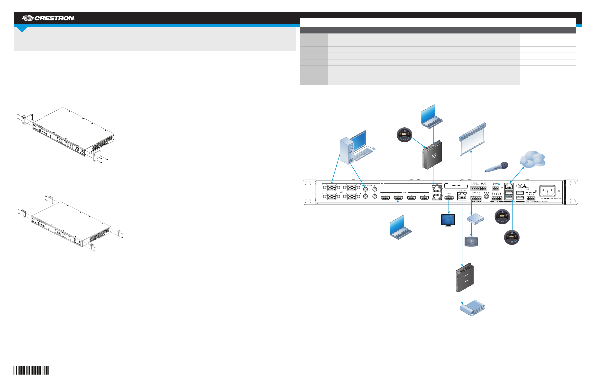
DO Make Connections to the Rear Panel
Make connections to the rear panel of the DMPS3-4K-150-C as follows:
VGA IN 1– 4: Connect to RGB (VGA), component, S-video, or composite
video sources.
AUDIO IN 1– 4: Connect to unbalanced audio sources.
®
HDMI IN 1–4: Connect to HDMI
DM IN 1–2: Connect to the DM 8G+™ output of DigitalMedia™
transmitters or other DigitalMedia devices or to third-party HDBaseT
1
devices.
HDMI OUT: Connect to the display.
DM OUT: Connect to the DM 8G+ input of a DigitalMedia receiver or other
DigitalMedia device or to a third-party HDBaseT device.
RELAY 1–2: Connect to controllable devices.
IN PUT: Connect to a digital or analog output device.
AUDIO OUT: Connect to the receiving device using the supplied 5-pin
interface connector.
IR OUT: Connect to the included Crestron
MIC IN: Connect to a microphone.
COM: Connect to the device to be controlled using the included 5-pin
interface connector.
LAN: Connect to the local area network.
USB 1– 4 (Type A): Connect to the USB port of TT-100 Series presentation
interfaces.
G: Connect to earth ground (building steel).
NE T: Connect to the 4-pin NET port of a Cresnet® device using the
included 4-pin interface connector.
100–240V~1.4A 50/60 Hz: Connect to a 120 V power outlet using the
included power cord.
audio/video sources.
®
STIRP IR emitter probe.
1
DO Check the Box
QUANTITY PRODUCT PART NUMBER
2 Bracket, Rack Ear, 1U 2032122
4 Bracket, Under Table Mount 20 41951
2 Connector, 3-Pin 2003575
2 Connector, 4-Pin 2003576
2 Connector, 5-Pin 2003577
1 Emitter Probe, IR, Crestron STIRP 20 01137
4 Foot, 0.5" x 0.5" x 0.23", Adhesive 2002389
1 Power Cord, 6' 7" (2 m) 20 0113 4
Not Included: Cables, Rack Mount Screws, and Table Mount Screws
®
Placing onto a Flat Surface
When placing the device onto a at surface or stacking it with other
equipment, attach the included feet near the corners on the underside of
the device.
DO Determine the Address of the Device
The DMPS3-4K-150-C can be addressed using the hostname of the device.
The default hostname is DMPS3-xxxxxxxx, where xxxxxxxx consists of the
last eight characters of the MAC address. For example, if the MAC address
is 00:10:7F:08:09:A A:05, the default host name is DMPS3-0809AA05. The
MAC address is labeled on the rear panel of the DMPS3-4K-150-C.
Alternatively, the DMPS3-4K-150-C can be addressed using the IP address
of the device. By default, DHCP is enabled. To set a static IP address, use
Crestron Toolbox™ on a PC that connects to the DMPS3-4K-150-C via
the Ethernet network or a USB connection to the COMPUTER port on the
front panel of the device. If the PC connects to the Ethernet network, the
Device Discovery Tool in Crestron Toolbox can be used to nd the current
IP address.
DO Commission the System
Using the web interface, congure the DMPS3-4K-150-C. To access the
web interface, open a web browser and go to the setup directory of the
DMPS3-4K-150-C by entering either of the following:
hostname/setup (hostname is the hostname of the device)
or
xxx.xxx.xxx.xxx/setup (xxx.xxx.xxx.xxx is the IP address of the device)
The DMPS3-4K-150-C also provides the built-in DMPS .AV Framework™
Base Program that enables complete system control without requiring
additional programming. Control is accomplished using the Crestron
TSW-752 Touch Screen (TSW-752-B-T DMPS3 PAK KIT), the Crestron
XPanel interface, or the Crestron Control App for Apple® iPad®.
All VT Pro-e® projects as well as the latest version of the DMPS .AV
Framework Base Program are available on the DMPS3-4K-150-C product
web page. For more information, refer to the DMPS .AV Framework Base
Software Operations Guide (Doc. 7646) at www.crestron.com/manuals.
DO Allow Automatic Switching or
Manually Select an Input
By default, automatic switching of inputs is enabled. Automatic switching
causes the last connected input to be routed to the output. The AUTO LED
lights to indicate that automatic switching is enabled.
To manually select and activate the desired input, press one of the VGA
(1–4), HDMI (1–4), or DM (1–2) INPUT SELECT buttons. Refer to the
following table for a summary of the LED behavior of selected and
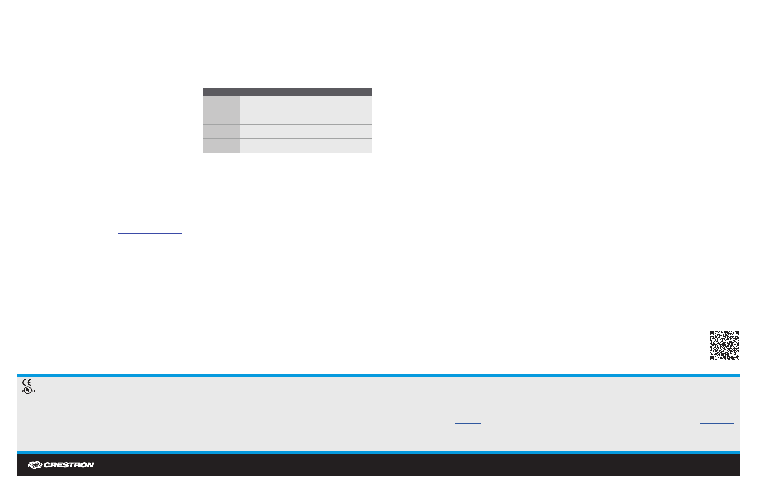
nonselected inputs.
COLOR DESCRIPTION
Solid green
Flashing green
Solid amber
Off
NOTE: Manual selection of an input disables automatic switching. When
automatic switching is disabled, the AUTO LED turns off.
The input is the active selection, and an incoming signal
is detected.
The input is the active selection, and an incoming signal
is not detected.
The input is not the active selection, and an incoming
signal is detected.
The input is not the active selection, and an incoming
signal is not detected.
As of the date o f manufacture, th e product ha s been tested and fo und to comply w ith speci cations for CE mar king.
This pro duct is List ed to applica ble UL Standards a nd requirement s by Underwriter s Laboratorie s Inc.
Federal Communications Commission (FCC) Compliance Statement
This devi ce complie s with part 15 of the FCC Rul es. Opera tion is subje ct to the following tw o condition s:
(1) This device m ay not cause harmf ul interfe rence, and (2) this dev ice must accept an y interfer ence rece ived, inclu ding inter ference th at may cause un desired opera tion.
Cauti on: Changes or mo dications not exp ressly approve d by the manufa cturer res ponsible fo r compliance cou ld void the user’s auth ority to ope rate the equipmen t.
Note: This equip ment has be en tested and f ound to compl y with the limits for a Cl ass B digital devi ce, pursua nt to part 15 of the FCC Rule s. These lim its are desi gned to provi de reasona ble protection ag ainst harm ful interferen ce in a residentia l
install ation. This equip ment generates , uses and ca n radiate rad io frequen cy energy and, if not i nstalled and us ed in accord ance with the instr uctions, may caus e harmful inter ference to ra dio communicati ons. However, there is no gu arantee that
interf erence wil l not occur in a pa rticular inst allation.
If this equ ipment doe s cause harmful in terference to ra dio or televi sion recep tion, which c an be determined by t urning the e quipment of f and on, the user is e ncourage d to try to correct t he interfe rence by one or more of t he following m easures:
• Reorient or relocate the receiving antenna
• Increa se the separ ation between th e equipmen t and receive r
• Connec t the equipment into a n outlet on a circui t differen t from that to which the r eceiver is conne cted
• Consul t the dealer o r an experie nced radio/T V technician for h elp
DO GUIDE
1. The DM IN and DM OUT ports are PoDM (Power over DM) and PoH (Power over
HDBaseT) PSE (Power Sourcing Equipment) ports. Any wiring that is connected to a PoDM
or PoH PSE port is for intra-building use only and should not be connected to a line that
runs outside of the building in which the PSE is located.
DO Learn More
Check the website for additional information
and the latest rmware updates.
Crestron Electronics
15 Volvo Drive, Rockleigh, NJ 07647
888.CRESTRON | www.crestron.com
Industry Canada (IC) Compliance Statement
CAN ICES-3(B)/NMB-3(B)
Rack Mounting Safety Precautions
• Elevated Operating Ambient Temperature: If installed in a closed or multi-unit rack assembly, the operating ambient temperature of the rack environment may be greater than room ambient temperature. Therefore, consideration should be
given to ins talling the e quipment in an envi ronment compati ble with the maxim um ambient te mperature (Tma) sp ecied by the manu facturer.
• Reduce d Airow: Insta llation of the e quipment in a rack s hould be suc h that the amou nt of airow requi red for safe o peration of t he equipment is not c ompromised.
• Mechanical Loading: Mounting of the equipment in the rack should be such that a hazardous condition is not achieved due to uneven mechanical loading.
• Circuit Overloading: Consideration should be given to the connection of the equipment to the supply circuit and the effect that overloading of the circuits might have on overcurrent protection and supply wiring. Appropriate consideration of
equipment nameplate ratings should be used when addressing this concern.
• Reliabl e Earthing: Reli able ear thing of rack-m ounted equipmen t should be mainta ined. Par ticular at tention sho uld be given to supply c onnections othe r than direct conn ections to the bra nch circuit (e .g., use of power s trips).
The speci c patents that c over Crestron pro ducts are listed a t patents.crestron.com. The produ ct warranty ca n be found at www.crestron.com/warranty.
Crestr on, the Crestr on logo, 3-Ser ies, .AV Framew ork, Cresnet , Crestron Toolb ox, DigitalMe dia, DM 8G+, and V T Pro-e are ei ther trademark s or registered t rademarks of Cr estron Elect ronics, Inc. in t he United Stat es and/or other c ountries. Ap ple and iPad are eit her trademark s or registered t rademarks
of Apple In c. in the United State s and/or other count ries. HDBaseT and the H DBaseT Alliance logo a re either trademark s or registered trad emarks of the H DBaseT Allian ce in the United S tates and/or othe r countries. HDM I and the HDMI l ogo are either tradem arks or regis tered tradema rks of HDMI
Licensin g LLC in the United S tates and/or o ther countrie s. UL and the UL log o are either trade marks or registe red trademark s of Underwrit ers Laborato ries, Inc. in the U nited States an d/or other coun tries. Other t rademarks, regi stered tradema rks, and trade na mes may be used in this do cument to refer
to either th e entities claiming t he marks and names or t heir products. C restron disclai ms any proprietar y interest in the ma rks and names of othe rs. Crestron is n ot responsible fo r errors in typog raphy or photogra phy.
This docum ent was written by t he Technical Publicat ions departmen t at Crestron.
©2015 Crestron Electronics, Inc.
DOC. 76 54D (204224 6) 05.15
Specic ations subject to c hange without not ice.
 Loading...