

Page 1

DM NVX™ Network AV
Encoders/Decoders
DM-NVX-E30
DM-NVX-D30
DM-NVX-E30C
DM-NVX-D30C
Product Manual
Crestron Electronics, Inc.
Page 2

Original Instructions
The U.S. English version of this document is the original instructions.
All other languages are a translation of the original instructions.
The product warranty can be found at www.crestron.com/legal/sales-terms-conditions-warranties.
The specific patents that cover Crestron products are listed at www.crestron.com/legal/patents.
Certain Crestron products contain open source software. For specific information, visit
www.crestron.com/legal/open-source-software.
Crestron, the Crestron logo, 3-Series, Crestron Toolbox, Crestron XiO Cloud, DigitalMedia, DM NVX, and DM NVX Director
are either trademarks or registered trademarks of Crestron Electronics, Inc. in the United States and/or other countries.
Dolby and Dolby Atmos are either trademarks or registered trademarks of Dolby Laboratories in the United States and/or
other countries. DTS HD and DTS:X are either trademarks or registered trademarks of DTS, Inc. in the United States and/or
other countries. HDMI and the HDMI logo are either trademarks or registered trademarks of HDMI Licensing LLC in the
United States and/or other countries. Active Directory is either a trademark or registered trademark of Microsoft
Corporation in the United States and/or other countries. DisplayPort is either a trademark or registered trademark of Video
Electronics Standards Association in the United States and/or other countries. Other trademarks, registered trademarks,
and trade names may be used in this document to refer to either the entities claiming the marks and names or their
products. Crestron disclaims any proprietary interest in the marks and names of others. Crestron is not responsible for errors
in typography or photography.
©2019 Crestron Electronics, Inc.
Page 3

Contents
Introduction ................................................................................................................................... 1
Physical Description .................................................................................................................... 2
DM-NVX-E30 and DM-NVX-D30 ........................................................................................................... 2
Front Panel, DM-NVX-E30 ................................................................................................................ 2
Front Panel, DM-NVX-D30 ............................................................................................................... 3
Rear Panel, DM-NVX-E30 and DM-NVX-D30 ............................................................................... 4
DM-NVX-E30C ........................................................................................................................................... 5
DM-NVX-D30C ........................................................................................................................................... 6
Configuration and Status .......................................................................................................... 7
DMF-CI-8 Chassis Details ........................................................................................................................ 7
Using the Web Interface .................................................................................................................... 7
Using SIMPL Windows ....................................................................................................................... 8
DM NVX Director Virtual Switching Appliance .................................................................................... 8
Stream Statistics ....................................................................................................................................... 9
Using the Web Interface .................................................................................................................... 9
Using SIMPL Windows ..................................................................................................................... 10
Multicast TTL (Time-to-Live) ................................................................................................................. 10
Using the Web Interface .................................................................................................................. 10
Using SIMPL Windows ...................................................................................................................... 11
DSCP (Differentiated Services Code Point) ...................................................................................... 12
EDID (Extended Display Identification Data) .................................................................................... 13
Subscriptions ............................................................................................................................................ 14
Using the Web Interface .................................................................................................................. 14
Using SIMPL Windows ..................................................................................................................... 15
7.1 Surround Sound Audio ...................................................................................................................... 15
Analog Audio Output .............................................................................................................................. 16
Using the Web Interface .................................................................................................................. 16
Using SIMPL Windows ..................................................................................................................... 16
Crestron XiO Cloud Service Connection ............................................................................................. 17
Enterprise-Grade Security ..................................................................................................................... 18
IEEE 802.1X Authentication ............................................................................................................ 18
Authentication Management ......................................................................................................... 19
Fan Control .............................................................................................................................................. 20
Using the Web Interface ................................................................................................................. 20
Using SIMPL Windows .................................................................................................................... 20
Automatic Firmware Update ................................................................................................................ 21
Product Manual – DOC. 8425A Contents • i
Page 4

HDCP 2.2 Compliance............................................................................................................... 22
IGMP Snooping .......................................................................................................................... 23
Troubleshooting ......................................................................................................................... 25
Appendix: Device Discovery ..................................................................................................... 27
ii • Contents Product Manual – DOC. 8425A
Page 5

Introduction
Crestron® DM NVX™ network AV encoders/decoders transport ultra high-definition 4K
video with 60 Hz frame rates and 4:4:4 color sampling over standard Gigabit Ethernet.
Support for High Dynamic Range (HDR) video and HDCP 2.2 ensures high picture quality
and compatibility with a variety of media sources. Using Pixel Perfect Processing
technology, a video signal is encoded and decoded to achieve imperceptible end-to-end
latency of less than 1 frame.
DM-NVX-E30(C) devices consist of the DM-NVX-E30 surface-mountable endpoint
and the DM-NVX-E30C card, which function as encoders (transmitters) only.
DM-NVX-D30(C) devices consist of the DM-NVX-D30 surface-mountable endpoint and
the DM-NVX-D30C card, which function as decoders (receivers) only. Compact in design,
the DM-NVX-E30 and DM-NVX-D30 are designed to fit in various locations, for example,
behind a flat panel display. The DM-NVX-E30C and DM-NVX-D30C are designed to
occupy the DMF-CI-8 card chassis.
NOTES:
• The DM-NVX-D30 and DM-NVX-D30C do not support scaling.
• DM-NVX-E30(C) encoders and DM-NVX-D30(C) decoders are compatible with
DM-NVX-350(C), DM-NVX-351(C), and DM-NVX-352(C) encoders/decoders.
If DM-NVX-E30(C) encoders are used with DM-NVX-35x(C) devices, the
DM-NVX-35x(C) devices must be in Receiver mode. If DM-NVX-D30(C) decoders are
used with DM-NVX-35x(C) devices, the DM-NVX-35x(C) devices must be in
Transmitter mode.
This manual provides information about the following:
• Physical description
• Configuration and status
• HDCP 2.2 compliance
• IGMP snooping
• Troubleshooting
In addition, information about device discovery of a DM NVX device using Crestron
Toolbox™ software is provided in the appendix of this manual. For installation
information, refer to the DM-NVX-E30/DM-NVX-D30 Quick Start (Doc. 8211) and the
DM-NVX-E30C/DM-NVX-D30C Quick Start (Doc. 8346) as applicable. For information
about designing a DM NVX system, refer to the DM NVX System Design Guide
(Doc. 7977). The documents are available at www.crestron.com/manuals
.
Product Manual – DOC. 8425A DM-NVX-E30(C)/DM-NVX-D30(C) Encoders/Decoders • 1
Page 6
Physical Description
The following sections provide information about the connectors, controls, and indicators
that are available on the DM-NVX-E30(C) and DM-NVX-D30(C) devices.
DM-NVX-E30 and DM-NVX-D30
This section provides information about the front and rear panels of the DM-NVX-E30
and DM-NVX-D30.
Front Panel, DM-NVX-E30
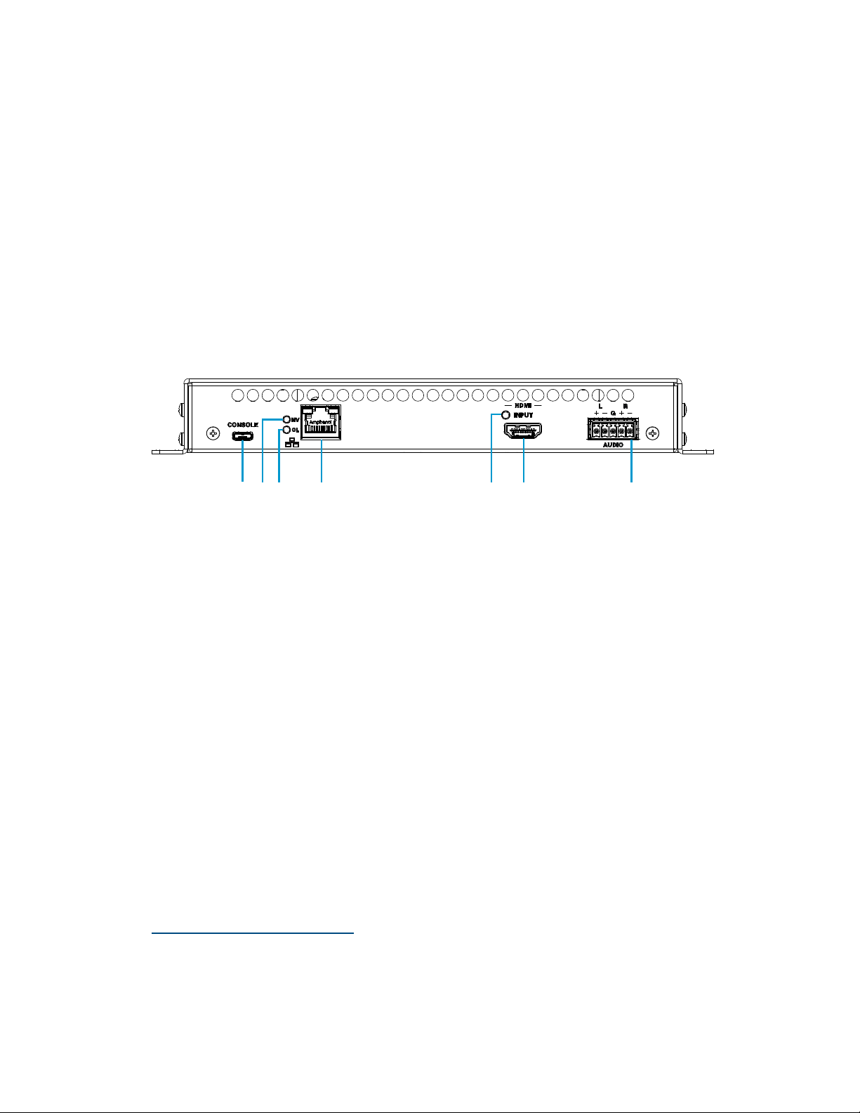
The following illustration shows the front panel of the DM-NVX-E30.
DM-NVX-E30 Front Panel
CONSOLE: Micro USB connector, female;
USB 2.0 computer console port for setup
NV LED: Green LED, indicates that the device is encoding (transmitting)
network video
OL LED: Green LED, indicates an online connection to a control system via Ethernet
LAN: 8-pin RJ-45 connector, female;
100BASE-TX/1000BASE-T Ethernet port;
PoE+ PD (powered device) port compatible with a PoE+ compliant Ethernet switch, a
Crestron DM-PSU-ULTRA-MIDSPAN, or an approved third-party PSE;
Green LED indicates Ethernet link status;
Amber LED indicates Ethernet activity
HDMI INPUT LED: Green LED, indicates sync detection at the HDMI® input
HDMI INPUT: HDMI Type A connector, female;
HDMI digital video/audio input (DVI and Dual-Mode DisplayPort™ interface
compatible)
2, 3
1
1
The LAN port must connect to a 1000BASE-T switch in order to stream network video.
2
The HDMI connection requires an appropriate adapter or interface cable to accommodate a DVI or
Dual-Mode DisplayPort signal. CBL-HD-DVI interface cables are sold separately.
3
Device control via CEC (Consumer Electronics Control) requires the use of a Crestron 3-Series® or later
control system.
2 • DM-NVX-E30(C)/DM-NVX-D30(C) Encoders/Decoders Product Manual – DOC. 8425A
Page 7
AUDIO: 5-pin 3.5 mm detachable terminal block;
Balanced/unbalanced stereo line-level audio output;
Output Impedance: 200 Ohms balanced, 100 Ohms unbalanced;
Maximum Output Level: 4 Vrms balanced, 2 Vrms unbalanced
NOTE: The analog audio output is functional only when the DM-NVX-E30 is receiving
a 2-channel stereo input signal.
Front Panel, DM-NVX-D30
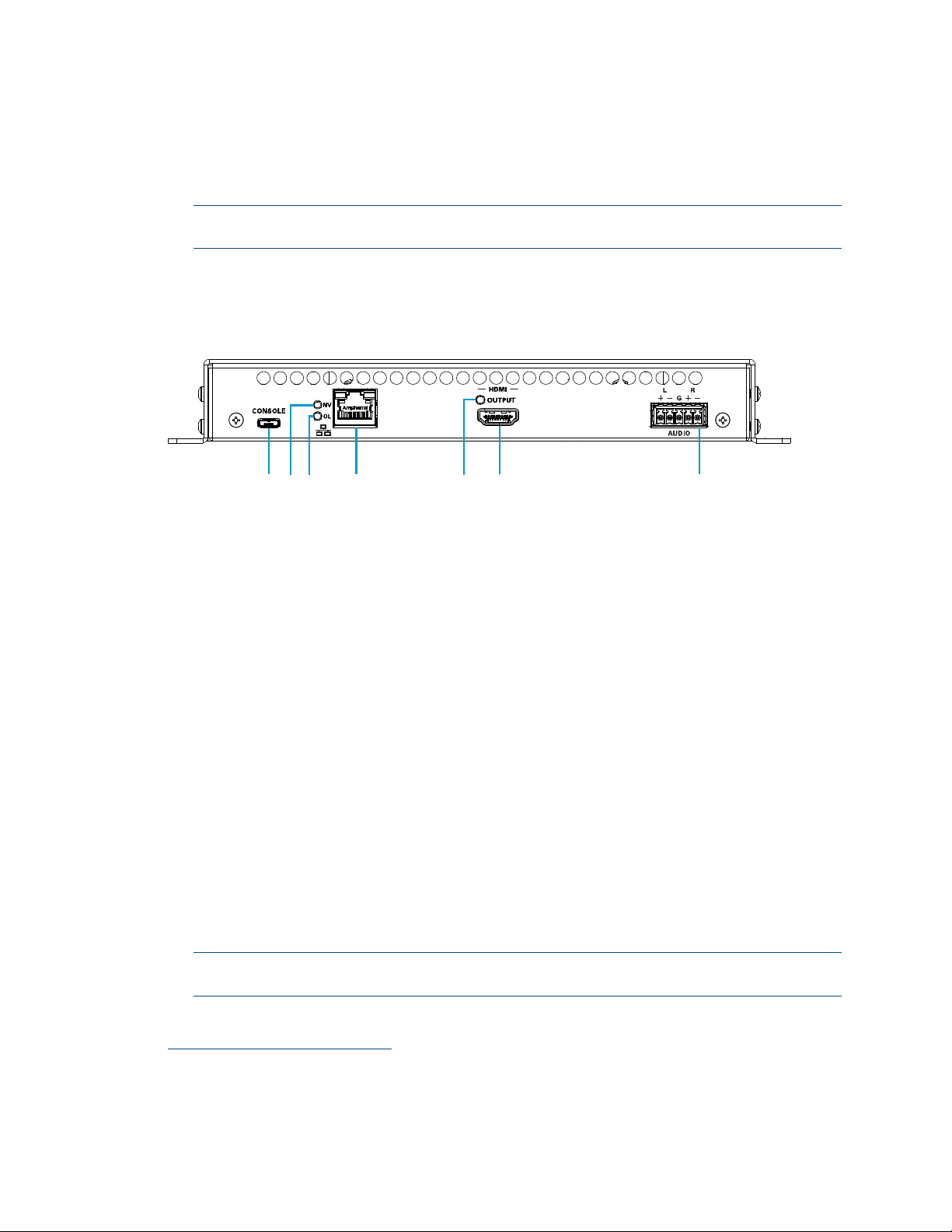
The following illustration shows the front panel of the DM-NVX-D30.
DM-NVX-D30 Front Panel
CONSOLE: Micro USB connector, female;
USB 2.0 computer console port for setup
NV LED: Green LED, indicates that the device is decoding (receiving) network video
OL LED: Green LED, indicates an online connection to a control system via Ethernet
LAN: 8-pin RJ-45 connector, female;
100BASE-TX/1000BASE-T Ethernet port;
PoE+ PD (powered device) port compatible with a PoE+ compliant Ethernet switch, a
Crestron DM-PSU-ULTRA-MIDSPAN, or an approved third-party PSE;
Green LED indicates Ethernet link status;
Amber LED indicates Ethernet activity
1
HDMI OUTPUT LED: Green LED, indicates video signal transmission at the
HDMI output
HDMI OUTPUT: HDMI Type A connector, female;
HDMI digital video/audio output (DVI compatible)
2, 3
AUDIO: 5-pin 3.5 mm detachable terminal block;
Balanced/unbalanced stereo line-level audio output;
Output Impedance: 200 Ohms balanced, 100 Ohms unbalanced;
Maximum Output Level: 4 Vrms balanced, 2 Vrms unbalanced
NOTE: The analog audio output is functional only when the DM-NVX-D30 is receiving
a 2-channel stereo input signal.
1
The LAN port must connect to a 1000BASE-T switch in order to stream network video.
2
The HDMI connection requires an appropriate adapter or interface cable to accommodate a DVI signal.
CBL-HD-DVI interface cables are sold separately.
3
Device control via CEC requires the use of a Crestron 3-Series or later control system.
Product Manual – DOC. 8425A DM-NVX-E30(C)/DM-NVX-D30(C) Encoders/Decoders • 3
Page 8
Rear Panel, DM-NVX-E30 and DM-NVX-D30
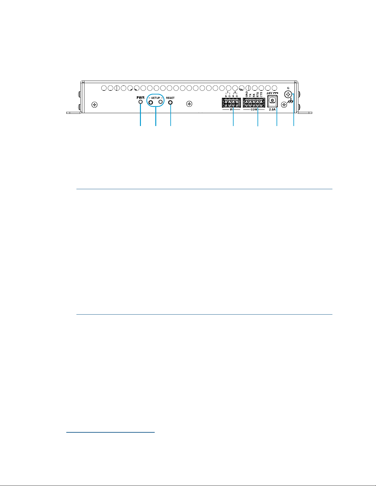
The following illustration shows the rear panel of the DM-NVX-E30 and DM-NVX-D30.
DM-NVX-E30 and DM-NVX-D30 Rear Panel
PWR: Bicolor green/amber LED, indicates operating power supplied via the power
pack (sold separately), PoE+ compliant Ethernet switch, or injector/PSE;
Lights amber while booting and green when operating
SETUP: Push button for on-screen display of IP address;
Red LED, indicates that the SETUP button is pressed and times out automatically.
NOTES:
• If the DM-NVX-D30 decoder is connected to a DM-NVX-E30(C) or
DM-NVX-35x(C) encoder, pressing the
for less than 10 seconds displays the decoder and encoder IP addresses.
The IP addresses are shown on the display connected to the HDMI output of
the decoder.
• If the DM-NVX-E30 encoder is connected to a DM-NVX-D30(C) decoder, pressing
the
SETUP button on the DM-NVX-E30 for less than 10 seconds displays the
encoder and decoder IP addresses. The IP addresses are shown on the display
connected to the HDMI output of the decoder.
• If the DM-NVX-E30 encoder is connected to a DM-NVX-35x(C) decoder,
pressing the
SETUP button on the DM-NVX-E30 displays the IP address of the
decoder only. The IP address is shown on the display connected to the HDMI
output of the decoder.
RESET: Recessed push button for hardware reset
IR 1–2: 4-pin 3.5 mm detachable terminal block;
Comprises two IR/serial ports
IR output up to 1.1 MHz;
1-way serial TTL/RS-232 (0–5 volts) up to 19200 baud;
Crestron IRP2 emitter sold separately
COM: 5-pin 3.5 mm detachable terminal block;
Bidirectional RS-232 port;*
Up to 115.2k baud, hardware and software handshaking support
SETUP button on the DM-NVX-D30
∗
∗
Device control via RS-232 and IR requires the use of a Crestron 3-Series or later control system.
4 • DM-NVX-E30(C)/DM-NVX-D30(C) Encoders/Decoders Product Manual – DOC. 8425A
Page 9
24VDC 2.0A: 2.1 x 5.5 mm DC power connector;
24 VDC power input;
Power pack included
Ground: 6-32 screw, chassis ground lug
DM-NVX-E30C
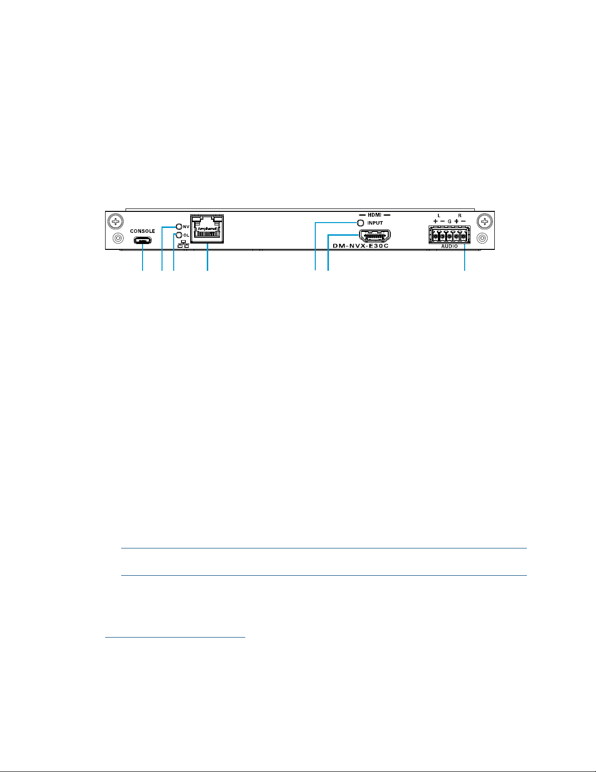
The following illustration shows the connectors, controls, and indicators that are
available on the DM-NVX-E30C.
DM-NVX-E30C
CONSOLE: Micro USB connector, female;
USB 2.0 computer console port for setup
NV LED: Green LED, indicates that the device is encoding (transmitting)
network video.
OL LED: Green LED, indicates an online connection to a control system via Ethernet
LAN: 100BASE-TX/1000BASE-T Ethernet port;
Green LED indicates Ethernet link status;
Amber LED indicates Ethernet activity
HDMI INPUT LED: Green LED, indicates sync detection at the HDMI input
HDMI INPUT: HDMI Type A connector, female;
HDMI digital video/audio input (DVI and Dual-Mode DisplayPort interface
compatible)
2, 3
AUDIO: 5-pin 3.5 mm detachable terminal block;
Balanced/unbalanced stereo line-level audio output;
Output Impedance: 200 Ohms balanced, 100 Ohms unbalanced;
Maximum Output Level: 4 Vrms balanced, 2 Vrms unbalanced
NOTE: The analog audio output is functional only when the DM-NVX-E30C is
receiving a 2-channel stereo input signal.
1
1
The LAN port must connect to a 1000BASE-T switch in order to stream network video.
2
Device control via CEC requires the use of a Crestron 3-Series or later control system.
3
The HDMI connection requires an appropriate adapter or interface cable to accommodate a DVI or
Dual-Mode DisplayPort signal. CBL-HD-DVI interface cables are sold separately.
Product Manual – DOC. 8425A DM-NVX-E30(C)/DM-NVX-D30(C) Encoders/Decoders • 5
Page 10
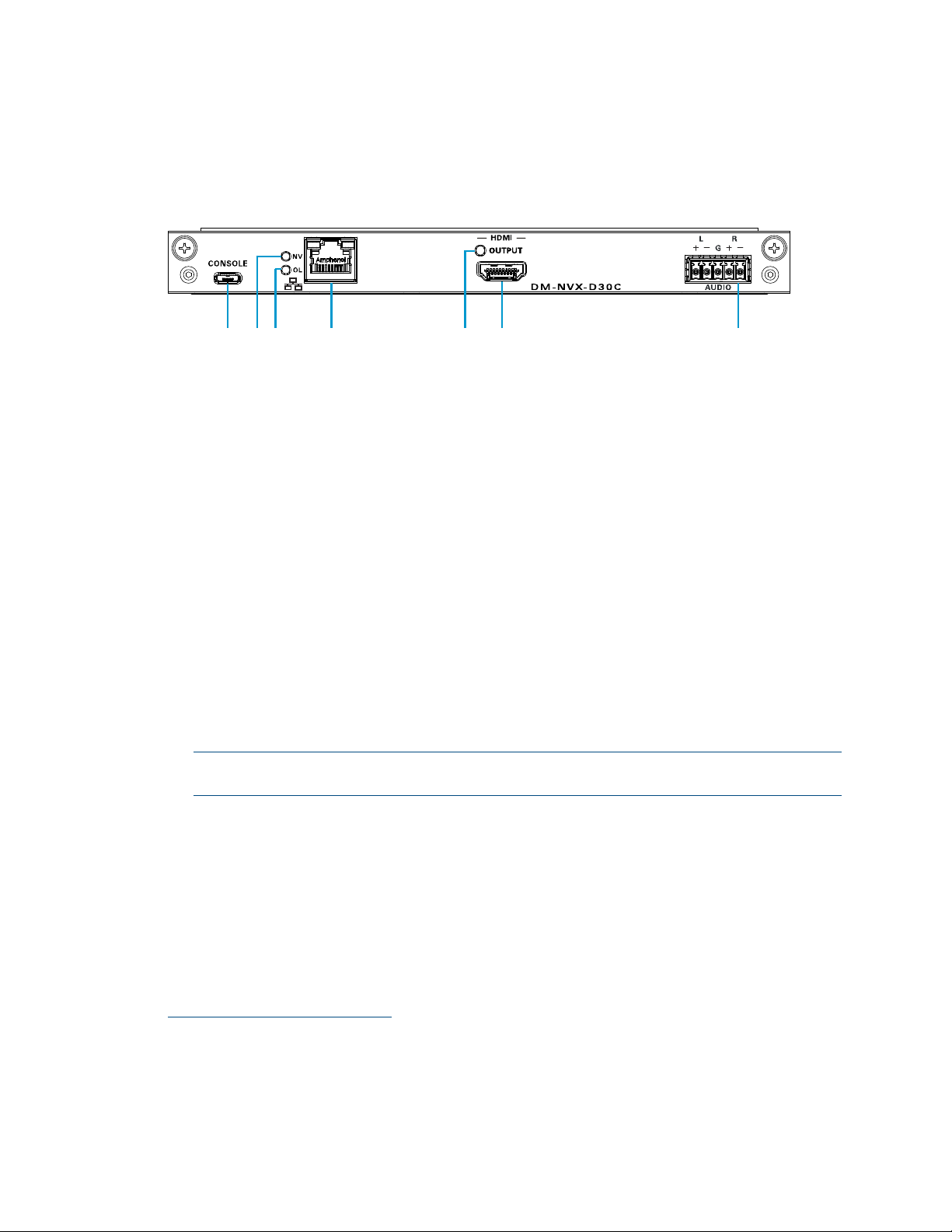
DM-NVX-D30C
The following illustration shows the connectors, controls, and indicators that are
available on the DM-NVX-D30C.
DM-NVX-D30C
CONSOLE: Micro USB connector, female;
USB 2.0 computer console port for setup
NV LED: Green LED, indicates that the device is decoding (receiving) network video.
OL LED: Green LED, indicates an online connection to a control system via Ethernet
LAN: 100BASE-TX/1000BASE-T Ethernet port;
1
Green LED indicates Ethernet link status;
Amber LED indicates Ethernet activity
HDMI OUTPUT LED: Green LED, indicates video signal transmission at the
HDMI output
HDMI OUTPUT: HDMI Type A connector, female;
HDMI digital video/audio output (DVI compatible)
2, 3
AUDIO: 5-pin 3.5 mm detachable terminal block;
Balanced/unbalanced stereo line-level audio output;
Output Impedance: 200 Ohms balanced, 100 Ohms unbalanced;
Maximum Output Level: 4 Vrms balanced, 2 Vrms unbalanced
NOTE: The analog audio output is functional only when the DM-NVX-D30C is
receiving a 2-channel stereo input signal.
1
The LAN port must connect to a 1000BASE-T switch in order to stream network video.
2
Device control via CEC requires the use of a Crestron 3-Series or later control system.
3
The HDMI connection requires an appropriate adapter or interface cable to accommodate a DVI signal.
CBL-HD-DVI interface cables are sold separately.
6 • DM-NVX-E30(C)/DM-NVX-D30(C) Encoders/Decoders Product Manual – DOC. 8425A
Page 11

Configuration and Status
This section provides information about configuring or viewing the following items using
the web interface and SIMPL Windows as applicable:
• DMF-CI-8 chassis details
• DM NVX Director™ virtual switching appliance
• Stream statistics
• Multicast TTL (Time-to-Live)
• DSCP (Differentiated Services Code Point)
• EDID (Extended Display Identification Data)
• Subscriptions
• 7.1 surround sound audio
• Analog audio output
• Crestron XiO Cloud™ service connection
• Enterprise-grade security
• Fan control
• Automatic firmware update
DMF-CI-8 Chassis Details
NOTE: DMF-CI-8 chassis details apply to the DM-NVX-E30C and DM-NVX-D30C only.
A DM NVX card occupies a DMF-CI-8 chassis. Information about the chassis can be
viewed using the web interface or SIMPL Windows.
Using the Web Interface
View DMF-CI-8 chassis information on the Status page. The Chassis Details section
displays the following information:
• Serial number of the chassis
• Number of the slot into which the card is installed
Product Manual – DOC. 8425A DM-NVX-E30(C)/DM-NVX-D30(C) Encoders/Decoders • 7
Page 12

Status Page – Chassis Details
Using SIMPL Windows
Using the top-level programming slot for the DM NVX card, program the
<ChassisSerialNumber_F> serial output join to report the serial number of the chassis.
Program the
<CardSlotInfo_F> serial output join to report the number of the slot into
which the card is installed.
DM NVX Director Virtual Switching Appliance
If a DM NVX device is managed by a DM NVX Director™ virtual switching appliance,
information about the appliance can be viewed using the web interface.
View DM NVX Director appliance information on the Status page. The DM NVX Director
section displays the following information:
• DM NVX Director hostname
• Domain name, number, and slot number to which the DM NVX device is assigned
8 • DM-NVX-E30(C)/DM-NVX-D30(C) Encoders/Decoders Product Manual – DOC. 8425A
Page 13

Status Page – DM NVX Director
Stream Statistics
Statistics can be displayed to indicate the number of packets received or transmitted,
the number of dropped packets, and the bit rate of the received stream. To enable or
disable stream statistics, use the web interface or SIMPL Windows as discussed in the
following sections.
Using the Web Interface
Configure stream statistics on the Stream page. In the Statistics section of the page,
set
Statistics to Enable or Disable. To reset statistics, click Reset Statistics.
For additional information, refer to the online help of the web interface.
NOTE: The bit rate of the stream appears on the Stream page of the DM-NVX-D30 and
DM-NVX-D30C only.
Stream Page - Statistics Configuration
Product Manual – DOC. 8425A DM-NVX-E30(C)/DM-NVX-D30(C) Encoders/Decoders • 9
Page 14

Using SIMPL Windows
For the DM-NVX-E30 and DM-NVX-E30C, configure stream statistics in Slot-01:
Stream Transmit. For the DM-NVX-D30 and DM-NVX-D30C, configure stream
statistics in
to enable the reporting of statistics. To disable statistics, trigger the
<StatisticsDisabled> digital input join. To clear the statistics, trigger the
<ResetStatistics> digital input join. The corresponding serial joins are updated when the
digital input joins are triggered. For additional information, refer to the SIMPL Windows
help file.
Slot-02: Stream Receive. Trigger the <StatisticsEnabled> digital input join
Multicast TTL (Time-to-Live)
NOTE: Multicast TTL configuration is applicable to the DM-NVX-E30 and
DM-NVX-E30C only.
Multicast TTL provides the ability to limit or extend the hop limit of a DM NVX stream
that traverses routers. In IPv4 multicasting, routers have a TTL threshold assigned to
each interface. Only multicast packets with a TTL greater than the threshold of the
interface are forwarded.
Multicast TTL can be set to any value ranging from 1 to 255. The default setting is 5.
To set a multicast TTL value, use the web interface or SIMPL Windows.
Using the Web Interface
Configure multicast TTL on the Stream page. In the Advanced section of the page, set a
multicast TTL value:
1. Set Auto Initiation to Disabled.
2. Stop the stream by clicking Stop.
3. Select the Custom TTL checkbox.
4. Enter the desired TTL value (1 to 255).
5. Set Auto Initiation to Enabled. The stream automatically restarts.
NOTE: Deselecting the Custom TTL checkbox returns the TTL value to the
default setting.
10 • DM-NVX-E30(C)/DM-NVX-D30(C) Encoders/Decoders Product Manual – DOC. 8425A
Page 15

Stream Page - Multicast TTL Configuration
Using SIMPL Windows
Configure multicast TTL as follows:
1. Using the top-level programming slot:
a. Trigger the <AutomaticInitiationDisabled> digital input join.
b. Trigger the <Stop> digital input join.
2. In Slot-01: Stream Transmit, set the <MulticastTTL> analog input join to the
desired value (
3. Using the top-level programming slot, trigger the <AutomaticInitiationEnabled>
digital input join. The stream automatically restarts.
For additional information, refer to the SIMPL Windows help file.
1 to 255).
Product Manual – DOC. 8425A DM-NVX-E30(C)/DM-NVX-D30(C) Encoders/Decoders • 11
Page 16

DSCP (Differentiated Services Code Point)
NOTE: DSCP configuration is applicable to the DM-NVX-E30 and DM-NVX-E30C only.
To implement Quality of Service (QoS), IP networks use the DSCP value. Within an
IP packet header, the DSCP defines a value from 0 to 63 that maps to a certain traffic
classification. Based on IT department policies, DSCP values are used within a network
to determine the treatment of packets in router queues, the routes of traffic flows, and
per-hop behavior. By default, DSCP is set to 32.
NOTE: Change the DSCP default setting of 32 only if required by IT department policies.
Configure DSCP on the Stream page. In the Advanced section of the page, set a
DSCP value:
1. Set Auto Initiation to Disabled.
2. Stop the stream by clicking Stop.
3. Select the Custom DSCP checkbox.
4. Enter the desired DSCP value (0 to 63).
5. Set Auto Initiation to Enabled. The stream automatically restarts.
NOTE: Deselecting the DSCP checkbox returns the DSCP value to the default setting.
Stream Page - DSCP Configuration
12 • DM-NVX-E30(C)/DM-NVX-D30(C) Encoders/Decoders Product Manual – DOC. 8425A
Page 17

EDID (Extended Display Identification Data)
NOTE: EDID configuration is applicable to the DM-NVX-E30 and DM-NVX-E30C only.
EDID configuration allows management of the EDID that is to be sent to the upstream
device connected to the HDMI input of the DM NVX device. If an EDID other than the
default EDID is desired, use the web interface to configure the EDID.
Configure EDID on the HDMI INPUT page. In the EDID section of the page, select the
desired EDID. For additional information, refer to the online help of the web interface.
HDMI INPUT Page - EDID Configuration
Product Manual – DOC. 8425A DM-NVX-E30(C)/DM-NVX-D30(C) Encoders/Decoders • 13
Page 18

Subscriptions
NOTE: Subscription configuration is applicable to the DM-NVX-D30 and
DM-NVX-D30C only.
Subscription of a DM NVX encoder to a DM NVX decoder sets up Real Time Streaming
Protocol (RTSP) negotiation between the DM NVX decoder and the DM NVX encoder.
When a stream is routed, the DM NVX decoder performs the Internet Group
Management Protocol (IGMP) join, which causes the decoder to join the multicast group
of the encoder. A maximum of 64 encoders can be subscribed to a single decoder.
To configure subscriptions, use the web interface or SIMPL Windows as discussed in the
following sections.
Using the Web Interface
Configure subscriptions on the Subscriptions and Routing pages:
1. On the Subscriptions page, do either of the following:
a. In the Subscribed Streams section, manually add each encoder that is to be
subscribed to the decoder or load one or more existing subscription lists
(*.xml). The default filename of the subscription list is subscription.xml.
NOTE: Subscribed transmitters can be reordered in the list. To do so, click the
encoder that is to be reordered in the list, and then click the up arrow
( ) or the down arrow ( ) until the encoder appears in the desired
location in the list.
b. In the Available Streams section of the page, click Subscribe Checked or
Subscribe for the encoders that are to be subscribed to the decoder.
Subscriptions Page
14 • DM-NVX-E30(C)/DM-NVX-D30(C) Encoders/Decoders Product Manual – DOC. 8425A
Page 19

2. In the DM NVX Routing section of the Routing page, select the desired encoder to
be routed to the decoder.
Routing Page
For additional information, refer to the online help of the web interface.
Using SIMPL Windows
NOTE: Selection of the encoders for subscription or selection of subscription lists can be
performed using the web interface only.
Manually select a subscribed encoder for routing in Slot-1000: XIO Routing. Set the
<VideoOut> analog input join to the desired encoder. For additional information, refer to
the SIMPL Windows help file.
7.1 Surround Sound Audio
DM NVX devices support the lossless transport of 7.1 surround sound audio, which
includes Dolby® TrueHD, Dolby Atmos®, DTS HD®, DTS:X® and uncompressed linear PCM
audio formats.
NOTE: The DM-NVX-D30 and DM-NVX-D30C cannot accept downmixed audio from a
DM-NVX-351 or DM-NVX-351C transmitter.
To configure 7.1 surround sound audio, set the desired EDID (refer to "EDID" on page 13).
Product Manual – DOC. 8425A DM-NVX-E30(C)/DM-NVX-D30(C) Encoders/Decoders • 15
Page 20

Analog Audio Output
The analog audio output can provide a stereo line-level signal to feed a local sound
system or sound bar. The output volume is adjustable via the web interface or
SIMPL Windows.
Using the Web Interface
Configure the volume of the analog audio output on the Output page. Set Analog Audio
Volume to the desired volume.
Output Page - Analog Settings Configuration
For additional information, refer to the online help of the web interface.
Using SIMPL Windows
Using the top-level programming slot for the DM NVX device, set the
<AnalogAudioOutputVolume> analog input join to the desired volume. For additional
information, refer to the SIMPL Windows help file.
16 • DM-NVX-E30(C)/DM-NVX-D30(C) Encoders/Decoders Product Manual – DOC. 8425A
Page 21

Crestron XiO Cloud Service Connection
The Crestron XiO Cloud™ service allows supported Crestron devices across an enterprise
to be managed and configured from one central and secure location in the cloud.
Connection to the Crestron XiO Cloud service can be enabled or disabled using the
web interface.
Configure the connection to the Crestron XiO Cloud service on the Device page. In the
Cloud Settings section of the page, set Cloud Configuration Service Connection to
Enabled (default setting) or Disabled.
Device Page – Cloud Configuration Service Connection
When Cloud Configuration Service Connection is set to Enabled, connection to the
Crestron XiO Cloud service is allowed. For instructions about connecting to the service,
refer to the DM-NVX-E30/DM-NVX-D30 Quick Start (Doc. 8211) or DM-NVX-E30C/
DM-NVX-D30C Quick Start (Doc. 8346) as appropriate. For information about using the
service, refer to the Crestron XiO Cloud User Guide (Doc. 8214). The documents are
available at
www.crestron.com/manuals.
Product Manual – DOC. 8425A DM-NVX-E30(C)/DM-NVX-D30(C) Encoders/Decoders • 17
Page 22

Enterprise-Grade Security
DM NVX devices incorporate advanced security features such as IEEE 802.1X
authentication, user and group authentication management, AES-128 content
encryption, PKI authentication, TLS (Transport Layer Security), SSH (Secure Shell), and
HTTPS (Hypertext Transfer Protocol Secure) to provide enterprise-grade security.
Configure IEEE 802.1X authentication as well as user and group authentication
management using the web interface.
IEEE 802.1X Authentication
IEEE 802.1X is a network standard designed to enhance the security of wireless and
wired LANs. The standard defines how to provide authentication for devices trying to
connect to other devices on the LAN.
Configure IEEE 802.1X authentication in the 802.1x Configuration section of the
Network page. For detailed information, refer to the online help of the web interface.
Network Page – IEEE 802.1X Configuration
18 • DM-NVX-E30(C)/DM-NVX-D30(C) Encoders/Decoders Product Manual – DOC. 8425A
Page 23

Authentication Management
Authentication management can be configured for users and groups including
Active Directory® credential management groups. Predefined access levels can also
be assigned.
Configure authentication management in the Authentication Management section of
the Device page. For detailed information, refer to the online help of the web interface.
Device Page – Authentication Management
Product Manual – DOC. 8425A DM-NVX-E30(C)/DM-NVX-D30(C) Encoders/Decoders • 19
Page 24

Fan Control
NOTE: Fan control is applicable to the DM-NVX-D30 only.
Configure fan control or view fan status using the web interface or SIMPL Windows.
Using the Web Interface
Configure fan control on the Device page. In the Fan Control section, set Fan Mode to
one of the following:
• Auto: (Default setting) The fan automatically turns off when the following two
conditions exist:
1. No video stream is present.
2. The internal temperature of the device does not exceed the normal
operating range.
• Always On: The fan runs continuously regardless of video stream status and
internal temperature of the device.
Fan status is indicated as either of the following:
• Full On: The fan is running.
• Off: The fan is not running.
Device Page – Fan Control
Using SIMPL Windows
Using the top-level programming slot for the DM-NVX-D30, set the <FanControl>
analog input join to the desired setting. The
the fan mode of operation. The
<FanStatus_F> analog output join reports the fan
<FanControl_F> analog output join reports
status. For additional information, refer to the SIMPL Windows help file.
20 • DM-NVX-E30(C)/DM-NVX-D30(C) Encoders/Decoders Product Manual – DOC. 8425A
Page 25

Automatic Firmware Update
A DM NXV device can be automatically updated with the latest firmware at scheduled
intervals. To configure automatic firmware update:
1. Using the Crestron Auto Update Tool, generate a manifest file (*. mft). The file is
placed on an FTP (File Transfer Protocol) or SFTP (Secure File Transfer Protocol)
server.
2. Using the DM NVX web interface, configure automatic firmware update in the
Auto Update section of the Device page:
a. Set Auto Update to Enabled.
b. In the Custom URL Path text box, enter the path to the manifest file in the
following FTP or SFTP URL format:
ftp://
username:password@host:port/path/filename
or
sftp://
where:
•
username
•
password
•
host
server
•
port
NOTE: The default FTP port number is 21. The default SFTP port number
is 22. Entry of a port number is necessary only if the port number differs
from the default value of 21 or 22.
•
path
•
filename
c. Set a schedule for the automatic firmware update by doing either of the
following:
• Select the desired Day of Week and Time of Day (24-hour format) values.
• Set the Poll Interval by entering a value from 60 to 65535 minutes.
A value of
username:password@host:port/path/filename
is the username on the FTP or SFTP server
is the password for the username
is the fully qualified domain name or IP address of the FTP or SFTP
is the connection port on the host
is the path to the manifest file
consists of the name and extension (.mft) of the manifest file
0 disables the Poll Interval.
3. Click Save Changes.
Clicking Update Now causes the firmware to be updated at the current time; however,
the schedule that is set in step 2c above remains in effect.
Product Manual – DOC. 8425A DM-NVX-E30(C)/DM-NVX-D30(C) Encoders/Decoders • 21
Page 26

Device Page – Auto Update
HDCP 2.2 Compliance
DM NVX devices are HDCP 2.2 compliant. HDCP 2.2, commonly referred to as HDCP 2, is
the next generation of HDCP (High-Definition Content Protection). Note the following
about HDCP 2:
• Compared to HDCP 1, HDCP 2 brings a higher level of cryptographic protection
to HDMI technology.
• HDCP 2 is not HDMI 2. It is possible to have a system built on HDCP 1 and
HDMI 2 or on HDCP 2 and HDMI 2.
• Although not all 4K content requires HDCP 2, most 4K consumer video content
does require HDCP 2.
• Any product that supports HDCP 2 also supports HDCP 1.
• HDCP matters only when the source demands HDCP. If the source demands
HDCP 2, then every device in the signal path must support HDCP 2.
• There are no issues related to HDCP 2 and cabling—all cables are compatible.
22 • DM-NVX-E30(C)/DM-NVX-D30(C) Encoders/Decoders Product Manual – DOC. 8425A
Page 27

IGMP Snooping
A DM NVX device sends IGMP join and leave messages.
NOTE: DM NVX devices support IGMPv2 and IGMPv3 only. IGMPv1 is not supported.
The IGMP snooping support version (v2 or v3) is configurable in the web interface.
The
Network Interface section of the Network page allows the desired version to be
selected. The default setting is
Network Page - Network Interface
NOTE: When a different IGMP snooping support version is selected, the DM NVX device
must be rebooted in order for the change to take effect.
The network switch port that connects to a DM NVX device must be enabled with
IGMPv2 or IGMPv3 snooping to prevent the switch from flooding the multicast
destination address traffic to all other connected ports. The multicast destination
address that is configured for the DM NVX device must be within the range of qualified
addresses. An upstream device such as a layer 3 router or switch periodically sends the
IGMP General Query messages to hosts in order to maintain group membership state
information. These queries can be either general or group-specific queries. The host
responds to queries with IGMP membership reports. The host running IGMPv2 or IGMPv3
may also send a Leave Group message to routers or switches in order to withdraw from
the group.
v2.
NOTES:
• DM NVX devices do not support random-timer and source-specific queries.
• As a host, a DM NVX device configured for support of IGMPv3 is compatible with a
network switch (IGMP querier) that is configured for IGMPv2.
IGMP snooping switches build forwarding lists by listening for and, in some cases,
intercepting IGMP messages. Although the software processing the IGMP messages may
maintain state information based on the full IP group addresses, the forwarding tables
are typically mapped to link layer addresses as shown in the following example.
Example of Forwarding Table
MULTICAST MAC ADDRESS MEMBER PORTS
01-00-5E-00-00-01 2, 7
01-00-5E-01-02-03 1, 2, 3, 7
01-00-5E-23-E2-05 1, 4
Because only the least significant 23 bits of the IP address are mapped to Ethernet
addresses (RFC 1112), there is a loss of information when forwarding solely on the
destination MAC address. For example, IP addresses 224.0.0.123 and 239.128.0.123 and
similar IP multicast addresses all map to MAC address 01-00-5e-00-00-7b for Ethernet.
Product Manual – DOC. 8425A DM-NVX-E30(C)/DM-NVX-D30(C) Encoders/Decoders • 23
Page 28

As a result, IGMP snooping switches may collapse IP multicast group memberships into a
single Ethernet multicast membership group.
In addition to building and maintaining lists of multicast group memberships, the
snooping switch must also maintain a list of multicast routers. When multicast packets
are forwarded, the packets should be forwarded not only on ports that have expressed
joins using IGMP but also on ports to which multicast routers are attached.
NOTES:
• Do not assign reserved multicast IP addresses to a DM NVX device for streaming.
For additional information, go to
https://www.iana.org/assignments/multicast-addresses/multicast-addresses.txt
.
• Multicast collision is a concern with IPv4. For example, multicast IPv4 addresses
224.8.7.6 and 229.136.7.6 translate to the same MAC address (01:00:5E:08:07:06).
The following items provide recommendations for configuration of a network switch for
IGMP snooping:
• Set the IGMP query interval to 60 seconds or 125 seconds. The recommended
setting is the default setting of the network switch.
• For good network performance, ensure that there is only one IGMP querier in the
network.
• Set IGMP snooping to v2 or v3.
• Enable IGMP snooping globally as well as for each specific VLAN for DM NVX
connected ports.
• Configure the network switch to drop unknown multicast packets.
• If the network switch supports IGMP fast leave, enable the configuration at the
port, global, or VLAN level.
• If the network switch supports PIM snooping, enable the configuration to prevent
flooding IP multicast traffic toward multicast router (mrouter) ports.
24 • DM-NVX-E30(C)/DM-NVX-D30(C) Encoders/Decoders Product Manual – DOC. 8425A
Page 29

properly.
Troubleshooting
The following table provides troubleshooting information. If further assistance is
required, contact a Crestron customer service representative.
DM NVX Encoder/Decoder Troubleshooting
PROBLEM POSSIBLE CAUSE(S) CORRECTIVE ACTION(S)
4K60 4:4:4 2-channel non-HDR or
4K60 4:4:4 2-channel HDR video
is intermittent.
The display flashes to a black
screen momentarily.
The video is not being displayed,
but the audio can be heard.
The video is intermittent.
(Applicable to the DM-NVX-E30
and DM-NVX-E30C) A message
indicating that the resolution is
unsupported appears on the
display.
There is no video or audio. Cable connections are faulty.
The display device is not
configured properly.
A Crestron HDMI cable is not
being used.
The Crestron HDMI cable exceeds
the maximum length of
20 ft (6.1 m).
Switching between HDR and
non-HDR content is occurring.
The HDCP settings of one or
more DigitalMedia™ devices in
the signal path do not support
the HDCP level of the source.
The display does not support the
HDCP level of the source.
The HDMI or Ethernet cable
connections are faulty.
The incorrect EDID is selected for
the HDMI input.
The resolution of the HDMI input
is not supported.
The incorrect EDID is selected for
the HDMI input.
The HDCP settings of one or
more DigitalMedia devices in
the signal path do not support
the HDCP level of the source.
Configure the display device
Refer to the display device
documentation for proper
configuration to support 4K60 4:4:4
2-channel non-HDR or 4K60 4:4:4 2channel HDR video.
Use a Crestron HDMI cable only.
Use a Crestron HDMI cable that does
not exceed 20 ft (6.1 m).
No action required. Flashing to a
black screen may occur on certain
TVs.
Ensure that the HDCP settings of all
DigitalMedia devices in the signal
path support the HDCP level of the
source.
Ensure that the display supports the
HDCP level of the source.
Verity that all cables are connected
securely.
Select the correct EDID.
Change the resolution of the input.
Verify that all cables are connected
securely.
Select the EDID supported by the
devices in the signal path.
Ensure that the HDCP settings of all
DigitalMedia devices in the signal
path support the HDCP level of the
source.
(Continued on following page)
Product Manual – DOC. 8425A DM-NVX-E30(C)/DM-NVX-D30(C) Encoders/Decoders • 25
Page 30

Set the analog audio mode to extract
snooping is enabled in the network
snooping in
Configure the network switch to drop
dress
DM NVX Encoder/Decoder Troubleshooting (Continued)
PROBLEM POSSIBLE CAUSE(S) CORRECTIVE ACTION(S)
The analog audio output is not
functioning.
The video flickers or drops when
the DM NVX device is touched or
when metal in the vicinity of the
device is touched.
The DM NVX device indicates that
the stream has started, but video
is not being displayed.
Video is flickering or video is not
displayed when multiple DM NVX
devices connect to a network
switch.
Video is flickering when multiple
DM NVX transmitters connect to
a network switch.
A DM NVX multicast stream
stopped.
DM NVX streaming video is not
seen in the receiver.
Video stops suddenly, and the
IGMP reports disappear in the
network switch.
(Applicable to compatible
DM-NVX-35x(C)
encoders/decoders only) The
analog audio mode is set to insert
audio.
(Applicable to compatible
DM-NVX-35x(C) encoders only)
An incorrect audio source is
selected.
The audio is multichannel
on a DM-NVX-E30 or
DM-NVX-E30C, which do not
downmix a 2-channel signal from
a multichannel surround sound
source.
The DM NVX device is not
properly grounded.
Neither IGMPv2 nor IGMPv3 is
enabled in the IGMP snooping
configuration.
Neither IGMPv2 nor IGMPv3
switch for the
associated port or VLAN.
The IGMP filter is not set to drop
an unknown multicast IP address.
The multicast address is not set
properly on the DM NVX device
The DM NVX receiver is not
configured with the correct
streaming URL and multicast
IP address.
The IGMP querier is not
configured correctly.
audio.
Set the audio source to analog audio.
Switch the audio input to
2-channel audio.
Properly ground the DM NVX device.
Ensure that IGMPv2 or IGMPv3 is
enabled on the network switch.
Enable IGMPv2 or IGMPv3
the correct VLAN.
the unknown multicast IP address.
Ensure that the multicast address is
not a duplicate of a multicast ad
that is set on another
DM NVX device. Use a valid multicast
address on the DM NVX device.
Configure the DM NVX receiver using
the correct streaming URL and
multicast IP address.
Configure the IGMP querier correctly.
The recommended setting is the
default setting of the network switch.
If, for any reason, the factory default settings of a DM NVX device must be restored,
do one of the following:
• On the Device page of the web interface, click the Restore button.
• From the Tools menu in the Crestron Toolbox software, select Text Console and
issue the
• Power cycle the device 10 times. After the tenth power cycle, wait until the device
boots and then press the
26 • DM-NVX-E30(C)/DM-NVX-D30(C) Encoders/Decoders Product Manual – DOC. 8425A
restore command.
SETUP button for 5 seconds.
Page 31

Appendix: Device Discovery
A DM NVX device can be discovered on the network by using the Device Discovery Tool
within the Crestron Toolbox software. To discover a DM NVX device:
1. Open the Crestron Toolbox software.
2. From the Tools menu, select Device Discovery Tool.
NOTES:
• You can also access the Device Discovery Tool by clicking the Device Discovery
Tool button ( ) in the Crestron Toolbox software toolbar.
• The security software running on the computer may send a program alert
regarding the attempt of the Crestron Toolbox software to connect to the
network. Allow the connection so that the Device Discovery Tool can be used.
The DM NVX device is discovered and is listed in the device list on the left side
of the screen. The associated host name, IP address, and firmware version are
also displayed.
3. In the Device Discovery Tool list, double-click the name of the DM NVX device
(
DM-NVX-E30, DM-NVX-D30, DM-NVX-E30C, or DM-NVX-D30C).
The Authentication dialog box opens.
4. Do the following:
a. Enter a user name and password. The default user name and password are
both
admin
b. Click OK.
A configuration pane appears for the DM NVX device.
5. Click the Web Configuration button in the Configuration page that appears on
the left side of the Device Discovery Tool.
NOTE: A warning indicating a security certificate problem or privacy error may
appear. Ignore the warning and continue to access the web interface of the
DM NVX device.
The Device Administration login page opens.
.
Product Manual – DOC. 8425A DM-NVX-E30(C)/DM-NVX-D30(C) Encoders/Decoders • 27
Page 32

Device Administration Login Page
6. Enter the user name and password. The default user name and password are
both
admin
.
NOTE: The user name and password are case sensitive.
7. Click Sign In.
The Status page of the DM NVX device opens. For additional information, refer
to the online help of the web interface.
28 • DM-NVX-E30(C)/DM-NVX-D30(C) Encoders/Decoders Product Manual – DOC. 8425A
Page 33

This page is intentionally left blank.
Product Manual – DOC. 8425A DM-NVX-E30(C)/DM-NVX-D30(C) Encoders/Decoders • 29
Page 34

Crestron Electronics, Inc. Product Manual – DOC. 8425A
15 Volvo Drive, Rockleigh, NJ 07647 (2053136)
Tel: 888.CRESTRON 05.19
Fax: 201.767.7576 Specifications subject to
www.crestron.com change without notice.
 Loading...